EP2397781A1 - Echangeur thermique - Google Patents
Echangeur thermique Download PDFInfo
- Publication number
- EP2397781A1 EP2397781A1 EP11152376A EP11152376A EP2397781A1 EP 2397781 A1 EP2397781 A1 EP 2397781A1 EP 11152376 A EP11152376 A EP 11152376A EP 11152376 A EP11152376 A EP 11152376A EP 2397781 A1 EP2397781 A1 EP 2397781A1
- Authority
- EP
- European Patent Office
- Prior art keywords
- heat exchanger
- cooling fluid
- exhaust pipe
- exhaust
- fluid flow
- Prior art date
- Legal status (The legal status is an assumption and is not a legal conclusion. Google has not performed a legal analysis and makes no representation as to the accuracy of the status listed.)
- Granted
Links
Images
Classifications
-
- F—MECHANICAL ENGINEERING; LIGHTING; HEATING; WEAPONS; BLASTING
- F28—HEAT EXCHANGE IN GENERAL
- F28D—HEAT-EXCHANGE APPARATUS, NOT PROVIDED FOR IN ANOTHER SUBCLASS, IN WHICH THE HEAT-EXCHANGE MEDIA DO NOT COME INTO DIRECT CONTACT
- F28D7/00—Heat-exchange apparatus having stationary tubular conduit assemblies for both heat-exchange media, the media being in contact with different sides of a conduit wall
- F28D7/10—Heat-exchange apparatus having stationary tubular conduit assemblies for both heat-exchange media, the media being in contact with different sides of a conduit wall the conduits being arranged one within the other, e.g. concentrically
- F28D7/103—Heat-exchange apparatus having stationary tubular conduit assemblies for both heat-exchange media, the media being in contact with different sides of a conduit wall the conduits being arranged one within the other, e.g. concentrically consisting of more than two coaxial conduits or modules of more than two coaxial conduits
-
- F—MECHANICAL ENGINEERING; LIGHTING; HEATING; WEAPONS; BLASTING
- F23—COMBUSTION APPARATUS; COMBUSTION PROCESSES
- F23J—REMOVAL OR TREATMENT OF COMBUSTION PRODUCTS OR COMBUSTION RESIDUES; FLUES
- F23J15/00—Arrangements of devices for treating smoke or fumes
- F23J15/06—Arrangements of devices for treating smoke or fumes of coolers
-
- F—MECHANICAL ENGINEERING; LIGHTING; HEATING; WEAPONS; BLASTING
- F24—HEATING; RANGES; VENTILATING
- F24D—DOMESTIC- OR SPACE-HEATING SYSTEMS, e.g. CENTRAL HEATING SYSTEMS; DOMESTIC HOT-WATER SUPPLY SYSTEMS; ELEMENTS OR COMPONENTS THEREFOR
- F24D5/00—Hot-air central heating systems; Exhaust gas central heating systems
- F24D5/06—Hot-air central heating systems; Exhaust gas central heating systems operating without discharge of hot air into the space or area to be heated
- F24D5/08—Hot-air central heating systems; Exhaust gas central heating systems operating without discharge of hot air into the space or area to be heated with hot air led through radiators
-
- F—MECHANICAL ENGINEERING; LIGHTING; HEATING; WEAPONS; BLASTING
- F24—HEATING; RANGES; VENTILATING
- F24D—DOMESTIC- OR SPACE-HEATING SYSTEMS, e.g. CENTRAL HEATING SYSTEMS; DOMESTIC HOT-WATER SUPPLY SYSTEMS; ELEMENTS OR COMPONENTS THEREFOR
- F24D2200/00—Heat sources or energy sources
- F24D2200/04—Gas or oil fired boiler
-
- F—MECHANICAL ENGINEERING; LIGHTING; HEATING; WEAPONS; BLASTING
- F24—HEATING; RANGES; VENTILATING
- F24D—DOMESTIC- OR SPACE-HEATING SYSTEMS, e.g. CENTRAL HEATING SYSTEMS; DOMESTIC HOT-WATER SUPPLY SYSTEMS; ELEMENTS OR COMPONENTS THEREFOR
- F24D2200/00—Heat sources or energy sources
- F24D2200/16—Waste heat
- F24D2200/18—Flue gas recuperation
-
- F—MECHANICAL ENGINEERING; LIGHTING; HEATING; WEAPONS; BLASTING
- F28—HEAT EXCHANGE IN GENERAL
- F28D—HEAT-EXCHANGE APPARATUS, NOT PROVIDED FOR IN ANOTHER SUBCLASS, IN WHICH THE HEAT-EXCHANGE MEDIA DO NOT COME INTO DIRECT CONTACT
- F28D21/00—Heat-exchange apparatus not covered by any of the groups F28D1/00 - F28D20/00
- F28D21/0001—Recuperative heat exchangers
- F28D21/0014—Recuperative heat exchangers the heat being recuperated from waste air or from vapors
-
- Y—GENERAL TAGGING OF NEW TECHNOLOGICAL DEVELOPMENTS; GENERAL TAGGING OF CROSS-SECTIONAL TECHNOLOGIES SPANNING OVER SEVERAL SECTIONS OF THE IPC; TECHNICAL SUBJECTS COVERED BY FORMER USPC CROSS-REFERENCE ART COLLECTIONS [XRACs] AND DIGESTS
- Y02—TECHNOLOGIES OR APPLICATIONS FOR MITIGATION OR ADAPTATION AGAINST CLIMATE CHANGE
- Y02B—CLIMATE CHANGE MITIGATION TECHNOLOGIES RELATED TO BUILDINGS, e.g. HOUSING, HOUSE APPLIANCES OR RELATED END-USER APPLICATIONS
- Y02B10/00—Integration of renewable energy sources in buildings
- Y02B10/70—Hybrid systems, e.g. uninterruptible or back-up power supplies integrating renewable energies
-
- Y—GENERAL TAGGING OF NEW TECHNOLOGICAL DEVELOPMENTS; GENERAL TAGGING OF CROSS-SECTIONAL TECHNOLOGIES SPANNING OVER SEVERAL SECTIONS OF THE IPC; TECHNICAL SUBJECTS COVERED BY FORMER USPC CROSS-REFERENCE ART COLLECTIONS [XRACs] AND DIGESTS
- Y02—TECHNOLOGIES OR APPLICATIONS FOR MITIGATION OR ADAPTATION AGAINST CLIMATE CHANGE
- Y02E—REDUCTION OF GREENHOUSE GAS [GHG] EMISSIONS, RELATED TO ENERGY GENERATION, TRANSMISSION OR DISTRIBUTION
- Y02E20/00—Combustion technologies with mitigation potential
- Y02E20/30—Technologies for a more efficient combustion or heat usage
Definitions
- the invention is directed to a tubular heat exchanger of a hall heating system, in which a heat exchange takes place between an exhaust gas flow and at least one cooling fluid flow. Furthermore, the invention is directed to a hall heating system with at least one exhaust and emitting a burner associated burner and such a heat exchanger. Likewise, the invention is directed to the use of such a heat exchanger and / or such a hall heating system for the use of the energy contained in the exhaust gas. Finally, the invention is directed to a method for operating an indoor heating system.
- hot air generators and infrared heaters are used, which are generally equipped with gas-fired burners.
- the advantage of infrared heaters or infrared heaters compared to hot air generators is that not as in conventional heating devices, the air is heated inside the hall or room, but takes place, a heating of the illuminated surfaces.
- infrared heaters work comparatively economically and are preferably used for heating industrial halls, workshops and sports halls.
- the problem arises in these known infrared heaters that the energy contained in the exhaust gas in the form of residual heat is not or only insufficiently used.
- a hall heating system which includes several infrared heaters.
- the infrared heaters are designed as so-called dark radiators, which are mounted below the hall ceiling.
- Each dark radiator has a closed burner with a jet pipe.
- the generated hot gases heat the surface of the radiant tubes, which in turn heat mainly as radiation in the hall.
- the exhaust gases of the individual burners are directed to the outside via a manifold.
- the leading to the outside manifold is extended so that the exhaust gas can condense within the extended line section before exiting into the open.
- a heating concept which combines the advantages of efficiency-optimized infrared heaters in the form of dark radiators and waste gas residual heat utilization in one system.
- a heat exchanger removes the thermal energy contained in the exhaust gas and transfers it to the flowing past in finned tubes water.
- the heat exchanger is designed as a compact unit with a safety device and high-quality thermal insulation, wherein the flow direction of the heat storage medium or water crosses the flow direction of the exhaust gas stream.
- a buffer tank receives the hot water, which is then fed via a simple control as needed in a normal pump-hot water heating network. The energy thus recovered can be used in many ways to warm water-based heating. Even with these measures firing efficiencies of over 100% can be realized.
- a disadvantage of this known prior art is that the exhaust pipe must be completely isolated, which significantly increases the cost of the system and the manufacturing cost. Because the system and In particular, the heat exchanger works with water as a cooling fluid or as a heat transfer medium, the system must be protected from frost. Also, the decrease in heat must be ensured. Due to the condensation temperature of the exhaust gas of about 50-55 ° C, the flow temperature of the water circuit of the heating system or the buffer storage must also be kept very low. Also, this concept is only economical for collection systems, but not for individual radiators, since the costs of such a heat exchanger are very high. In addition, the system has a greatly reduced efficiency in part-load operation. In particular, the excessive temperature exhaust gas is exhausted via a bypass line when heat can not be removed from the system. Also, this known system requires a high planning effort.
- the invention has for its object to provide a solution that is improved in a structurally simple manner and cost of the overall efficiency of a heating system in both the full load and in part load operation.
- the heat exchanger of a hall heating system is tubular and comprises a core tube, an exhaust pipe circumferentially surrounding the core tube and an outer tube surrounding the exhaust pipe circumferentially.
- a first longitudinal end of the heat exchanger has a feed for a total cooling fluid flow, wherein a second longitudinal end of the heat exchanger is connected to a discharge line discharging at least part of the total cooling fluid flow.
- a flow divider arranged in the region of the first longitudinal end of the heat exchanger divides the total cooling fluid flow into a first cooling fluid flow and into a second cooling fluid flow.
- the core tube extends between the first longitudinal end and the second longitudinal end of the heat exchanger and is in fluid communication with the flow divider that supplies the core tube with the first cooling fluid flow.
- an exhaust gas ring gap is formed between the exhaust pipe and the core tube, through which flows in the region of the second longitudinal end of the heat exchanger supplied and discharged in the region of the first longitudinal end of the heat exchanger exhaust gas stream.
- An annular gap formed between the outer tube and the exhaust pipe is in fluid communication with the flow divider which supplies the annular gap with the second cooling fluid flow. The heat exchange from the exhaust gas flow to the two cooling fluid flows takes place in opposite radial directions.
- the hall heating system has at least one exhaust-emitting burner and a burner associated burner, which is arranged in an indoor space to be heated and connected to the at least one exhaust gases laxative exhaust pipe, which is disposed within the heated indoor space and the opening to a free Exhaust system leads.
- At least one heat exchanger according to one of claims 1 to 6 is arranged, which is arranged downstream of the exhaust pipe and upstream of the exhaust system, wherein the exhaust pipe of the heat exchanger is in flow communication with the exhaust pipe and the exhaust system.
- An associated with the heat exchanger conveyor promotes the total cooling fluid flow to the first longitudinal end of the heat exchanger, wherein the second longitudinal end of the heat exchanger is connected to at least one, at least a portion of the heated in the heat exchanger totaldefluidstroms consumer.
- the heat exchange in the heat exchanger from the exhaust gas flow to the two cooling fluid flows takes place in opposite radial directions.
- an exhaust gas flow is generated by at least one burner associated with a heating device, which is passed through an exhaust pipe via an exhaust pipe associated with at least one heat exchanger to an exhaust system leading to the outside, wherein the exhaust gas stream in the at least one heat exchanger by a Exhaust gas ring gap which is formed between the exhaust pipe and a core tube extending in the interior of the exhaust pipe is conveyed therethrough.
- a radial double-sided heat transfer or heat transfer in opposite radial directions of the heat contained in the exhaust gas flow is carried out, in which the heat of the exhaust gas stream is transmitted both to a first, in the core tube promoted cooling fluid flow and to a second cooling fluid flow which is conveyed through an annular gap formed between an outer tube circumferentially surrounding the exhaust pipe and the exhaust pipe.
- the invention provides a possibility with which the overall efficiency of a heating system, in particular a hall heating system, both for the full load and for the part load operation is improved and increased in a structurally simple manner and cost.
- the cooling of the exhaust gas takes place until condensation, wherein the cooling fluid used for heat transfer of the two cooling fluid streams is air, which is preferably heated to 30-38 ° C during heat exchange and supplied by means of a fan to a hall or office space as warm air can.
- a portion of the preheated air ie, either the first or the second flow of cooling fluid, or the entire, preheated air for boosting the combustion air temperature used and fed to a burner.
- the entire heat exchanger may be made of aluminum, wherein the individual tubes may have a wall thickness of 1.5 mm.
- the streamlined, smooth and least resistive construction of the heat exchanger requires only minimal additional energy to achieve the condensation. Therefore efficiencies of up to 108% are possible.
- any hall heating systems can be retrofitted with a heat exchanger according to the invention, wherein the heat exchanger can also be operated in conjunction with a plurality of burners.
- the heat exchanger is suitable for operation with negative pressure and positive pressure exhaust systems.
- the heat exchanger is dimensioned such that the temperature of the exhaust gas is lowered within the heat exchanger into the condensation region.
- the heat exchanger has such a size or such a thermally effective area that the temperature of the exhaust gas is lowered within the heat exchanger and to the exhaust passage to a value at which the exhaust gas condenses in the heat exchanger.
- the heat exchanger is therefore adaptable by means of appropriate dimensioning to various conditions for a variety of heating systems.
- the second cooling fluid flow serves as a kind of thermal insulation and prevents by own heat absorption that the heat contained in the exhaust gas is released unused to the environment. Therefore, insulation for the heat exchanger is unnecessary.
- heat transfer takes place on the inner peripheral wall (corresponding to the core tube) of the exhaust gas ring gap to the first cooling fluid flow, so that a total of one double-sided and one in opposite radial directions (Radially directed inwards to the first cooling fluid flow and radially outward directed to the second fluid flow) acting heat transfer from the exhaust gas flow to the cooling fluid flows.
- the cooling fluid used in the form of air is divided into a first and a second cooling fluid flow for heat exchange with the exhaust gas stream, which surround and flow over the exhaust gas ring gap formed between the cooling tube and the exhaust pipe.
- a flow collector is arranged in the region of the second longitudinal end of the heat exchanger, which merges the first and second cooling fluid streams and directs them to the discharge line as the total cooling fluid flow or partial cooling fluid flow.
- the first cooling fluid flow heated in the core tube can either be combined with the second cooling fluid flow heated in the annular gap between the outer tube and exhaust pipe by means of the flow collector or be used as heated partial cooling fluid flow, for example for heating a room, wherein it is also conceivable to use this partial cooling fluid flow preheated combustion air to increase the combustion air temperature to use.
- the second longitudinal end of the heat exchanger may be connected to a sectionabtextechnisch for the separate discharge of the first or the second cooling fluid flow.
- the cross-sectional area of the core tube through which the first cooling fluid flow is greater than the cross-sectional area of the exhaust ring gap formed between the core tube and the exhaust pipe and / or as the cross-sectional area of the second coolant fluid flow between the outer tube and the exhaust pipe formed annular gap.
- the core tube has a greater longitudinal extent than the exhaust gas pipe.
- the outer tube, the exhaust pipe and the core tube have a circular cross-section and are arranged substantially concentric with each other.
- the invention provides that the exhaust pipe is guided with its first end in the vicinity of the second longitudinal end of the heat exchanger and with its second end in the vicinity of the flow divider radially outwardly beyond the outer circumference of the outer tube. Since the core tube has at least the same axial length as the exhaust pipe, it is ensured that within the entire heat exchanger, the heat transfer takes place up to the out of the heat exchanger ends of the exhaust pipe.
- the temperature of the exhaust gas stream after leaving the heat exchanger is at most 70 ° C or that the temperature of the exhaust gas stream is cooled to at least 70 ° C within the heat exchanger to the outlet end of the exhaust pipe or lowered into its condensation region.
- the use of a low-cost plastic exhaust system is possible.
- the cooling fluid streams which are preferably formed from air, can also be advantageously used for heating halls or offices or even for raising the combustion air temperature
- the temperature of the first and / or the second cooling fluid flow after leaving the (at least one) heat exchanger is at least 30 ° C or that the first cooling fluid flow and / or the second cooling fluid flow within the (at least one) heat exchanger is heated to at least 30 ° C.
- the invention provides in an embodiment of the method that the first, flowing in the core tube and heated cooling fluid flow and / or the second, flowing in the annular gap between the outer tube and the exhaust pipe and heated cooling fluid flow to the at least one burner as preheated combustion air is / is.
- the first, flowing in the core tube and heated cooling fluid flow and / or the second, flowing in the annular gap between the outer tube and the exhaust pipe and heated cooling fluid flow for heating a room or for a gate curtain are used / becomes.
- the hall heating system In order to increase the effectiveness of the heat transfer from the exhaust gas to the cooling fluid is provided in the hall heating system according to the invention that extends the core tube inside the exhaust pipe, wherein between the first and the second longitudinal end of the exhaust pipe between the core tube and the exhaust pipe, the exhaust gas wherein a first longitudinal end of the core tube is in fluid communication with the cooling fluid supplying device or with the first longitudinal end of the core tube via a flow divider.
- Flow divider a single, provided by the supply device total cooling fluid flow can be used, so that an additional device for providing cooling fluid is unnecessary.
- an infrared heater in the form of a dark radiator is used, wherein a gas-powered burner with a jet pipe is part of the dark radiator or the infrared heater.
- the at least one burner may be part of a light radiator, a hot air generator or a vacuum or multi-burner system.
- a discharge device for removing the condensate formed in the exhaust pipe is provided downstream of the at least one heat exchanger and upstream of the exhaust system.
- the discharge device may optionally have at least one neutralization box, so that the condensate can be discharged into the sewer system.
- a plurality of heat exchangers may be provided and used, which are connected to one or more exhaust pipes.
- the heat exchangers can be arranged either parallel to one another or in series or even parallel to one another and in series.
- different large-sized heat exchangers can be used to meet a variety of requirements for efficient exhaust gas heat exchange.
- the invention provides that a heat transfer device adjoins the second longitudinal end of the heat exchanger.
- This additional heat transfer device can be adapted to specific boundary conditions, which differ from those of the heat exchanger according to the invention, which is why this is suitable for a heat exchange with the exhaust gas, but not for a heat transfer to a consumer.
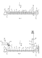
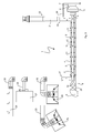
- FIGS. 1 to 3 a heat exchanger 1 according to the invention is shown according to a first embodiment, whereas the FIGS. 4 and 5 show a heat exchanger 1 'according to a second embodiment.
- the in schematic sectional views in the FIGS. 1 to 3 illustrated heat exchanger 1 according to the first embodiment is elongated and tubular and comprises an elongated core tube 2, which is surrounded by a substantially exhaust pipe 3 circumferentially. Furthermore, the heat exchanger 1 comprises an elongated outer tube 4 which substantially surrounds the outer circumference of the exhaust pipe 3.
- the core tube 2, the exhaust pipe 3 and the outer pipe 4 have a circular cross section and are arranged concentrically with each other. In addition to the circular shape, it is also conceivable that the individual Tubes may have a polygonal or oval cross-section.
- a feed opening 6 is provided through which the heat exchanger 1 is supplied with a total cooling fluid flow 7.
- the fluid of the total cooling fluid flow 7 is air coming from the environment, although another gaseous or even liquid fluid would be conceivable.
- the second longitudinal end 8 of the heat exchanger 1 is connected to a discharge line 9, from which at least part of the total cooling fluid flow 7 conveyed into the heat exchanger 1 can be removed.
- the tube opening of the core tube 2 is arranged, which acts as a flow divider 10 in the first embodiment.
- the total cooling fluid flow 7 is divided into a first cooling fluid flow 11 and a second cooling fluid flow 12.
- the flow divider 10 is in fluid communication with the core tube 2 extending between the first and second longitudinal ends 5 and 8 of the heat exchanger 1 and supplies the core tube 2 with the first cooling fluid flow 11. Further, the flow divider is formed with a between the exhaust pipe 3 and the outer tube 4 Annular gap 13 in flow communication and supplies it with the second cooling fluid flow 12. Between the exhaust pipe 3 and the core tube 2, an exhaust gas ring gap 14 is formed.
- the exhaust gas ring gap 14 is supplied with an exhaust gas flow 15 which flows through the exhaust gas ring gap 14 in the direction of the first longitudinal end 5 of the heat exchanger 1 and away from and away from the heat exchanger 1 in the region of the first longitudinal end 5 becomes.
- the heat exchange between the exhaust gas flow 15 and the first and second cooling fluid flow 11 and 12 takes place according to the countercurrent principle, ie that the first and the second cooling fluid flow 11 and 12 are conveyed against the flow direction of the exhaust gas flow 15 within the heat exchanger 1 and flow.
- the heat transfer is thus considered in the longitudinal or axial direction of the heat exchanger 1 according to the countercurrent principle, with structurally related restrictions, the heat exchanger 1 could alternatively be operated on the DC principle.
- the heat exchange takes place at an axial position of the heat exchanger 1 radially on both sides of the walls of the exhaust pipe 4 and the core tube 2 and the heat transfer from the exhaust stream 15 to thedefluidström1 11, 12 takes place in two opposite radial directions, in an inwardly directed Direction to the first cooling fluid flow 11 and in an outward direction to the second cooling fluid flow 12th
- the heat exchange described above takes place, wherein expediently the core tube 2 extends between the first longitudinal end 5 and the second longitudinal end 8 of the heat exchanger 1.
- the core tube 2 In the region of the second longitudinal end 8 of the heat exchanger 1 ends the core tube 2, whose outlet-side opening acts as a flow collector 16.
- the flow collector 16 brings the first and second cooling fluid flow 11 and 12 together again to the total cooling fluid flow 7, which now has a higher temperature by the heat exchange, as at the first longitudinal end 5 of the heat exchanger 1.
- the length and the cross section of the individual tubes of the heat exchanger 1 are dimensioned so that the temperature of the merged at the second longitudinal end 8 of the heat exchanger 1 cooling fluid streams 11, 12 is at least 30 ° C, whereas the temperature of the exhaust gas stream 15 after leaving the heat exchanger 1 is at most 70 ° C.
- the condition for this is that the cross-sectional area of the core tube 2 through which the first cooling fluid flow 11 flows is greater than the cross-sectional area of the exhaust gas ring gap 14 formed between the core tube 2 and the exhaust tube 3 and / or as the flow through the second cooling fluid flow 12 Cross-sectional area of the annular gap 13 formed between the outer tube 4 and the exhaust pipe 3.
- the core tube 2 have a greater longitudinal extent than the exhaust pipe 3.
- the flow collector 16 may be omitted, so that the two heated cooling fluid streams 11, 12 are not brought together, but separated from each other as Clauskühlfluidströme from the heat exchanger 1 and fed according to different consumers.
- the heat exchanger 1 may be connected to a Generalabloomtechnisch not shown in detail for the separate discharge of the first and the second cooling fluid flow 11, 12.
- the outer tube 4 is quasi a kind of shell, under which the exhaust pipe 3 and the core tube 2 are arranged.
- a first end 17 and a second end 18 of the exhaust pipe 3 are arranged radially outside of the outer tube 4.
- the main part of the exhaust pipe 3 runs parallel to the core tube 2 within the outer tube 4. Only in the end regions of the exhaust pipe 3 in the region of the second longitudinal end 8 of the heat exchanger 1, the first end 17 through the wall of the outer tube 4 to the outside over the outer circumference of the outer tube 4 led.
- the second end 18 of the exhaust pipe 3 which is led out of the outer tube 4 in the region of the first longitudinal end 5 of the heat exchanger 1. How further the FIGS.
- the exhaust pipe 3 thus has a U-shaped configuration, wherein the two legs of the U extend substantially transversely to the longitudinal extent of the core tube 2 and the pipe section of the exhaust pipe 3 connecting the two legs surrounds the core pipe 2.
- the in the FIGS. 1 to 3 shown heat exchanger 1 can be used in a hall heating system, where it can be used universally in all fired heating systems for the use of energy contained in the exhaust gas.
- the hall heating system comprises at least one burner, which is associated with a heating device 19 and emits exhaust gases, the exhaust gas flow over 15 an exhaust pipe 20 are passed from the burner or the heater 19 away to the heat exchanger 1 described above, wherein the exhaust pipe 20 is in flow communication with the first end 17 of the exhaust pipe 3.
- the exiting at the second end 18 of the exhaust pipe 3 exhaust gas stream 15 is then supplied via a further line 21 to an exhaust system 22, from which the cooled exhaust gas stream 15 is passed into the open.
- the heat exchanger 1 is - follows the flow path of the exhaust stream 15 - downstream of the exhaust pipe 20 and upstream of the exhaust system 22, wherein the exhaust pipe 3 of the heat exchanger 1 is in flow communication with the exhaust pipe 20 and the exhaust system 22.
- the burner or the heater 19, the exhaust pipe 20 and the heat exchanger 1 are arranged together in a hall space to be heated.
- FIG. 2 shows the heat exchanger 1 according to the invention, which is used in combination with the designed as an infrared heating device 19 in the form of a dark radiator 23.
- a burner not shown generates hot gases which heat the surface of a jet pipe.
- the jet tube emits the heat predominantly as radiation vertically downwards and is used for heating.
- the exhaust gas flow 15 conveyed by the dark radiator 23 via the exhaust pipe 20 to the first end 17 of the exhaust pipe 3 is cooled within the heat exchanger 1 to the second end 18 of the exhaust pipe 3 to at least 70 ° C or into the condensation region.
- the condensate can then be discharged in the region of the second end 18 of the exhaust pipe 3 by means of a discharge device 24 which is arranged upstream of the exhaust system 22, wherein the discharge device 24 may further comprise at least one neutralization box, so that a discharge of the condensate into the wastewater is possible ,
- FIG. 3 are further conceivable combinations of the heat exchanger 1 according to the invention shown with different heating devices.
- the used for indoor heating heat exchanger 1 is also used in this case in a hall heating system having at least one burner of a heater whose exhaust gases collected and over the exhaust pipe 20 are led to the heat exchanger 1.
- the burner is arranged in a hall space to be heated, wherein the exhaust pipe 9 and the heat exchanger 1 arranged downstream of the burner are likewise arranged within the indoor space to be heated.
- the exhaust pipe 20 can promote exhaust air from a burner of an obliquely arranged light radiator 25 or a vertically arranged light radiator 26, so that the heat exchanger 1 according to the invention can also be used in combination with light radiators belonging to the group of infrared heaters.
- the exhaust air of a burner of a hot air generator 27, which is conveyed via the exhaust pipe 20 to the first end 17 of the exhaust pipe 3, are used for heat transfer in the heat exchanger 1. It is also conceivable, however, to use the heat exchanger 1 in conjunction with a vacuum or multi-burner system 28, the hot exhaust gases also reaching the first end 17 of the exhaust pipe 3 via the exhaust pipe 20 and being used to increase the efficiency in the heat exchanger 1.
- the two cooling fluid streams 11 and 12 are heated at each of these applications within the heat exchanger 1 to at least 30 ° C.
- one of the two cooling fluid streams 11 or 12 or both can be used for heating a room or for a gate curtain.
- cooling fluid streams 11, 12 are passed through a further heat exchanger 29 for the use of existing in the cooling fluid streams 11, 12 heat.
- the heat energy present in the cooling fluid streams 11, 12 can subsequently via the discharge line 9 to another consumer, which need not necessarily be arranged in the same building as the heat exchanger 1, are provided.
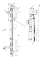
- FIG. 4 a second embodiment of a heat exchanger 1 'is shown, wherein FIG. 5 an enlarged section of the first longitudinal end 5 of the heat exchanger 1 'shows.
- the total cooling fluid flow 7 is supplied to the core tube 2 at its tube opening arranged in the region of the first longitudinal end 5.
- a predominant portion of the total cooling fluid flow 7 flows through the core tube 2 as the first cooling fluid flow 11 and toward the second longitudinal end 8 of the heat exchanger 1 '.
- a portion of the total cooling fluid flow 7 is passed in the end region of the core tube 2 via a U-shaped flow divider 10 'to the outer tube 4, which is arranged concentrically to the exhaust pipe 3 and the core tube 2, but which in comparison to that in the FIGS.
- the 1 to 3 illustrated embodiment has a lower longitudinal extent than the core tube 2.
- the outer tube 4 is attached to the exhaust pipe 3 and sealed there end, wherein the second cooling fluid flow 12 passes through the U-shaped flow divider 10 'in the annular gap 13 between the outer tube 4 and the exhaust pipe 3.
- the second cooling fluid flow 12 is passed within the annular gap 13 up to a U-shaped and arranged at the second longitudinal end 8 of the heat exchanger l'flow collector 16 ', via which the second cooling fluid flow 12 the first cooling fluid flow 12 at the second longitudinal end 8 of the heat exchanger 1'. is supplied.
- the discharge line 9 which - as described above for the first embodiment - may be in flow communication with one or more consumers.
- the first and second embodiments of the heat exchanger 1, 1 ' have great similarities, so that reference is made to the above statements for a detailed description.
- the flowed through by the first cooling fluid flow 11 cross-sectional area of the core tube 2 is greater than that of the exhaust gas flow 15th
- the cross-sectional area of the core tube 2 traversed by the first cooling fluid flow 11 is greater than the cross-sectional area of the flow between the second cooling fluid flow 12 and the cross-sectional area of the core tube 2
- the core tube 2 has a greater axial length than the exhaust pipe 3 on outer tube 4 and the exhaust pipe 3 formed annular gap.
- the essential differences between the heat exchanger 1 of the first embodiment and the heat exchanger 1 'of the second embodiment relate predominantly to different configurations of the flow divider 10 or 10' and the flow collector 16 or 16 ', whose characteristic features have been described above.
- an exhaust gas flow 15 is generated by at least one burner associated with the heating device 19.
- the exhaust gas stream 15 is passed through the exhaust pipe 20 via the exhaust pipe 3 assigned to the heat exchanger 1 or 1 'to the exhaust system 22 leading to the outside.
- the exhaust gas flow 15 is conveyed through the exhaust gas ring gap 14 from the second longitudinal end 8 to the first longitudinal end 5 of the heat exchanger 1, 1'.
- the heat transfer of the heat contained in the exhaust gas stream 15 takes place on the first and second cooling fluid flow 11 and 12, wherein the exhaust gas flow 15 against the flow direction of the cooling fluid flows 11, 12 flows.
- the heat transfer takes place in radially opposite directions, that is, the heat of the exhaust gas is discharged both radially inwardly to the flowing in the core tube 2 cooling fluid flow 11 and radially outwardly to the flowing in the annular gap 13 cooling fluid flow 12.
- the first cooling fluid flow 11 and the second cooling fluid flow 12 or only one of the two cooling fluid flows 11, 12 are heated to at least 30 ° C. within the heat exchanger 1, 1 '.
- the first cooling fluid flow 12, which is heated in its flow through the core tube 2, or the second cooling fluid flow 12, which is heated in its flow through the annular gap 13, the burner of the heater 19 are supplied as preheated combustion air.
- only one of the two heated cooling fluid streams 11, 12 can be supplied to the burner as preheated combustion air. It is also conceivable that both or one of the two heated cooling fluid streams 11, 12 are used for heating the hall space in which the heat exchanger is located, or for a gate veil.
- the invention is characterized by a three-shell and formed only of aluminum exhaust gas heat exchanger 1, 1 ', in which the heat transfer takes place in countercurrent principle.
- the exhaust gas fed from a burner to the exhaust gas diver 1, 1 ' is cooled down until it condenses in the exhaust gas ring gap 14.
- the primary cooling of the exhaust gas flow 15 takes place via the inner core tube 2, wherein the second cooling fluid flow 12 in the outer annular gap 13 prevents heat from being released to the external environment.
- the first cooling fluid flow 11, which flows through the core tube 2, is heated during heat exchange to 30-38 ° C and supplied for example to the room to be heated via a fan. Furthermore, the first cooling fluid flow 11 can be combined with the second cooling fluid flow 12 in the outer annular gap 15.
- the second cooling fluid flow 12 of the outer annular gap 13 can be used for increasing the combustion air temperature.
- the heated air of the two or only one of the two cooling fluid streams 11, 12 can be used, inter alia, for ancillary rooms, mezzanines, gate veils or process engineering applications. Due to the use of aluminum as Material for the components of the heat exchanger 1, 1 ', the optimum heat transfer is ensured, whereas the wall thickness of 1.5 mm, the longevity of the heat exchanger 1, 1' ensures.
- the combination of two or more devices or heaters with burners on a heat exchanger 1, 1 ' is possible.
- Existing heating systems can be retrofitted with the inventive heat exchanger 1, 1 'manufacturer independent.
- the heat exchanger 1, 1 ' can be used in all directly fired heating systems (dark radiators, vacuum systems in vacuum operation and overpressure systems, air heaters), condensation is ensured both in full load and in partial load operation and condensate removal can be done via neutralization boxes.
- the lowering of the temperature of the exhaust gas stream 15 to a maximum of 70 ° C allows the use of plastic exhaust systems.
- an operation with negative pressure and positive pressure exhaust systems possible.
- the heat exchanger 1, 1 ' is modularly adaptable to all systems by changing the tube lengths and / or cross sections.
Landscapes
- Engineering & Computer Science (AREA)
- Mechanical Engineering (AREA)
- General Engineering & Computer Science (AREA)
- Physics & Mathematics (AREA)
- Thermal Sciences (AREA)
- Chemical & Material Sciences (AREA)
- Combustion & Propulsion (AREA)
- Heat-Exchange Devices With Radiators And Conduit Assemblies (AREA)
Priority Applications (2)
| Application Number | Priority Date | Filing Date | Title |
|---|---|---|---|
| EP11152376.7A EP2397781B2 (fr) | 2011-01-27 | 2011-01-27 | Echangeur thermique |
| DE202011051724U DE202011051724U1 (de) | 2011-01-27 | 2011-10-21 | Wärmetauscher |
Applications Claiming Priority (1)
| Application Number | Priority Date | Filing Date | Title |
|---|---|---|---|
| EP11152376.7A EP2397781B2 (fr) | 2011-01-27 | 2011-01-27 | Echangeur thermique |
Publications (3)
| Publication Number | Publication Date |
|---|---|
| EP2397781A1 true EP2397781A1 (fr) | 2011-12-21 |
| EP2397781B1 EP2397781B1 (fr) | 2013-10-09 |
| EP2397781B2 EP2397781B2 (fr) | 2016-12-28 |
Family
ID=44148367
Family Applications (1)
| Application Number | Title | Priority Date | Filing Date |
|---|---|---|---|
| EP11152376.7A Active EP2397781B2 (fr) | 2011-01-27 | 2011-01-27 | Echangeur thermique |
Country Status (2)
| Country | Link |
|---|---|
| EP (1) | EP2397781B2 (fr) |
| DE (1) | DE202011051724U1 (fr) |
Cited By (4)
| Publication number | Priority date | Publication date | Assignee | Title |
|---|---|---|---|---|
| CN105004201A (zh) * | 2015-07-17 | 2015-10-28 | 中国华能集团公司 | 一种尿素溶液水解制氨反应器出口换热器 |
| CN105021037A (zh) * | 2015-07-07 | 2015-11-04 | 宁波北仑尚鼎工业炉有限公司 | 一种对烟气余热回收利用的天然气坩埚炉 |
| EP3121521A1 (fr) * | 2015-07-24 | 2017-01-25 | Oscar Pallaro | Dispositif de chauffage avec des radiateurs |
| CN109379828A (zh) * | 2018-11-29 | 2019-02-22 | 烟台海灵健康科技有限公司 | 一种热等离子体双层冷却降温装置 |
Citations (5)
| Publication number | Priority date | Publication date | Assignee | Title |
|---|---|---|---|---|
| US2847193A (en) * | 1954-08-30 | 1958-08-12 | Richard H Carter | Heat exchanger |
| US4390125A (en) * | 1981-02-12 | 1983-06-28 | Detroit Radiant Products Company | Tube-fired radiant heating system |
| JPH06300470A (ja) * | 1993-04-09 | 1994-10-28 | Hisaka Works Ltd | 3重管式熱交換器及び加熱・冷却ユニット |
| CA2544221A1 (fr) * | 2006-04-18 | 2007-10-18 | Solaronics, Inc. | Radiateur a infrarouges a faible intensite variable |
| US20100300663A1 (en) * | 2009-05-29 | 2010-12-02 | Ming-Li Tso | Heat exchanger |
Family Cites Families (1)
| Publication number | Priority date | Publication date | Assignee | Title |
|---|---|---|---|---|
| DE3326004A1 (de) † | 1983-07-19 | 1985-02-07 | Georg 8311 Baierbach Niedermeier | Waermetauscher |
-
2011
- 2011-01-27 EP EP11152376.7A patent/EP2397781B2/fr active Active
- 2011-10-21 DE DE202011051724U patent/DE202011051724U1/de not_active Expired - Lifetime
Patent Citations (5)
| Publication number | Priority date | Publication date | Assignee | Title |
|---|---|---|---|---|
| US2847193A (en) * | 1954-08-30 | 1958-08-12 | Richard H Carter | Heat exchanger |
| US4390125A (en) * | 1981-02-12 | 1983-06-28 | Detroit Radiant Products Company | Tube-fired radiant heating system |
| JPH06300470A (ja) * | 1993-04-09 | 1994-10-28 | Hisaka Works Ltd | 3重管式熱交換器及び加熱・冷却ユニット |
| CA2544221A1 (fr) * | 2006-04-18 | 2007-10-18 | Solaronics, Inc. | Radiateur a infrarouges a faible intensite variable |
| US20100300663A1 (en) * | 2009-05-29 | 2010-12-02 | Ming-Li Tso | Heat exchanger |
Cited By (5)
| Publication number | Priority date | Publication date | Assignee | Title |
|---|---|---|---|---|
| CN105021037A (zh) * | 2015-07-07 | 2015-11-04 | 宁波北仑尚鼎工业炉有限公司 | 一种对烟气余热回收利用的天然气坩埚炉 |
| CN105004201A (zh) * | 2015-07-17 | 2015-10-28 | 中国华能集团公司 | 一种尿素溶液水解制氨反应器出口换热器 |
| EP3121521A1 (fr) * | 2015-07-24 | 2017-01-25 | Oscar Pallaro | Dispositif de chauffage avec des radiateurs |
| CN109379828A (zh) * | 2018-11-29 | 2019-02-22 | 烟台海灵健康科技有限公司 | 一种热等离子体双层冷却降温装置 |
| CN109379828B (zh) * | 2018-11-29 | 2023-05-09 | 烟台海灵健康科技有限公司 | 一种热等离子体双层冷却降温装置 |
Also Published As
| Publication number | Publication date |
|---|---|
| EP2397781B2 (fr) | 2016-12-28 |
| DE202011051724U1 (de) | 2012-01-17 |
| EP2397781B1 (fr) | 2013-10-09 |
Similar Documents
| Publication | Publication Date | Title |
|---|---|---|
| DE102008025831B4 (de) | Kühlstruktur für den Körper eines Kristallzüchtungsofens | |
| EP2910855B1 (fr) | Brûleur à récupérateur avec échangeur de chaleur supplémentaire | |
| EP2397781B1 (fr) | Echangeur thermique | |
| WO1992020975A1 (fr) | Appareil de chauffage d'air | |
| EP3428533B1 (fr) | Dispositif de gaz d'échappement pour une installation de combustion dans un véhicule | |
| EP2031331A2 (fr) | Dispositif de nettoyage pour systèmes de condensation à air ou échangeurs thermiques analogues | |
| DE202010011138U1 (de) | Ventilatoreneinheit zur Beförderung eines Luftstroms in einem Kanal | |
| DE69300289T2 (de) | Vorrichtung zur Reinigung von Abgasen. | |
| DE29616022U1 (de) | Anlage zur Rückgewinnung von Wärme aus den Abgasen von Feuerungsanlagen | |
| EP0128463B1 (fr) | Appareil de chauffage des locaux pour des locaux de petite dimension | |
| EP2149636B1 (fr) | Dispositif de chauffage d'un caloporteur notamment pour machines de laverie et utilisation préférée du dispositif | |
| CH692061A5 (de) | Be- und Entlüftungsvorrichtung zur Zu- und Abfuhr von Luft in einem Gebäude. | |
| EP3016792A1 (fr) | Outil d'extrusion pour tête de soufflage de film ainsi que tête de soufflage | |
| EP2290662A1 (fr) | Transformateur de type sec | |
| DE2115257A1 (de) | Wassererhitzer | |
| CH665019A5 (de) | Waermeuebertrager, insbesondere zum kuehlen von gas aus einem hochtemperaturreaktor. | |
| DE102010012006A1 (de) | Wärmetauscher für eine thermische Abluftreinigungsanlage und Verfahren zum Reinigen eines Abluftstroms | |
| EP2348269A1 (fr) | Système de récupération de chaleur sur un four rotatif | |
| EP1439354B1 (fr) | Echangeur de chaleur | |
| EP0464586B1 (fr) | Procédé et dispositif pour la purification catalytique d'air d'échappement | |
| DE102010041130A1 (de) | Halterungsvorrichtung zum Haltern von Empfängermodulen für konzentrierte Solarstrahlung in einem solarthermischen Kraftwerk und solarthermisches Kraftwerk | |
| EP2420370A1 (fr) | Dispositif de chauffage des bords d'une ouverture de remplissage d'un tube en matière synthétique | |
| EP2395294B1 (fr) | Chaudière sectionnable | |
| DE202016101937U1 (de) | Vorrichtung zur Rückgewinnung von Wärmeenergie und Reinigung von Rauchgasen oder Dampf | |
| DE202016000810U1 (de) | Vorrichtung zur Übertragung von Wärmeenergie an ein Wärmeträgermedium einer Heizungsanlage |
Legal Events
| Date | Code | Title | Description |
|---|---|---|---|
| AK | Designated contracting states |
Kind code of ref document: A1 Designated state(s): AL AT BE BG CH CY CZ DE DK EE ES FI FR GB GR HR HU IE IS IT LI LT LU LV MC MK MT NL NO PL PT RO RS SE SI SK SM TR |
|
| AX | Request for extension of the european patent |
Extension state: BA ME |
|
| PUAI | Public reference made under article 153(3) epc to a published international application that has entered the european phase |
Free format text: ORIGINAL CODE: 0009012 |
|
| 17P | Request for examination filed |
Effective date: 20120320 |
|
| TPAC | Observations filed by third parties |
Free format text: ORIGINAL CODE: EPIDOSNTIPA |
|
| 17Q | First examination report despatched |
Effective date: 20130102 |
|
| GRAP | Despatch of communication of intention to grant a patent |
Free format text: ORIGINAL CODE: EPIDOSNIGR1 |
|
| GRAS | Grant fee paid |
Free format text: ORIGINAL CODE: EPIDOSNIGR3 |
|
| INTG | Intention to grant announced |
Effective date: 20130807 |
|
| GRAA | (expected) grant |
Free format text: ORIGINAL CODE: 0009210 |
|
| INTG | Intention to grant announced |
Effective date: 20130813 |
|
| AK | Designated contracting states |
Kind code of ref document: B1 Designated state(s): AL AT BE BG CH CY CZ DE DK EE ES FI FR GB GR HR HU IE IS IT LI LT LU LV MC MK MT NL NO PL PT RO RS SE SI SK SM TR |
|
| REG | Reference to a national code |
Ref country code: GB Ref legal event code: FG4D Free format text: NOT ENGLISH |
|
| REG | Reference to a national code |
Ref country code: CH Ref legal event code: EP Ref country code: AT Ref legal event code: REF Ref document number: 635732 Country of ref document: AT Kind code of ref document: T Effective date: 20131015 |
|
| REG | Reference to a national code |
Ref country code: IE Ref legal event code: FG4D Free format text: LANGUAGE OF EP DOCUMENT: GERMAN |
|
| REG | Reference to a national code |
Ref country code: DE Ref legal event code: R096 Ref document number: 502011001444 Country of ref document: DE Effective date: 20131205 |
|
| REG | Reference to a national code |
Ref country code: NL Ref legal event code: T3 |
|
| PG25 | Lapsed in a contracting state [announced via postgrant information from national office to epo] |
Ref country code: SI Free format text: LAPSE BECAUSE OF FAILURE TO SUBMIT A TRANSLATION OF THE DESCRIPTION OR TO PAY THE FEE WITHIN THE PRESCRIBED TIME-LIMIT Effective date: 20131009 |
|
| REG | Reference to a national code |
Ref country code: LT Ref legal event code: MG4D |
|
| PG25 | Lapsed in a contracting state [announced via postgrant information from national office to epo] |
Ref country code: NO Free format text: LAPSE BECAUSE OF FAILURE TO SUBMIT A TRANSLATION OF THE DESCRIPTION OR TO PAY THE FEE WITHIN THE PRESCRIBED TIME-LIMIT Effective date: 20140109 Ref country code: IS Free format text: LAPSE BECAUSE OF FAILURE TO SUBMIT A TRANSLATION OF THE DESCRIPTION OR TO PAY THE FEE WITHIN THE PRESCRIBED TIME-LIMIT Effective date: 20140209 Ref country code: HR Free format text: LAPSE BECAUSE OF FAILURE TO SUBMIT A TRANSLATION OF THE DESCRIPTION OR TO PAY THE FEE WITHIN THE PRESCRIBED TIME-LIMIT Effective date: 20131009 Ref country code: FI Free format text: LAPSE BECAUSE OF FAILURE TO SUBMIT A TRANSLATION OF THE DESCRIPTION OR TO PAY THE FEE WITHIN THE PRESCRIBED TIME-LIMIT Effective date: 20131009 Ref country code: SE Free format text: LAPSE BECAUSE OF FAILURE TO SUBMIT A TRANSLATION OF THE DESCRIPTION OR TO PAY THE FEE WITHIN THE PRESCRIBED TIME-LIMIT Effective date: 20131009 Ref country code: LT Free format text: LAPSE BECAUSE OF FAILURE TO SUBMIT A TRANSLATION OF THE DESCRIPTION OR TO PAY THE FEE WITHIN THE PRESCRIBED TIME-LIMIT Effective date: 20131009 |
|
| PG25 | Lapsed in a contracting state [announced via postgrant information from national office to epo] |
Ref country code: RS Free format text: LAPSE BECAUSE OF FAILURE TO SUBMIT A TRANSLATION OF THE DESCRIPTION OR TO PAY THE FEE WITHIN THE PRESCRIBED TIME-LIMIT Effective date: 20131009 Ref country code: PL Free format text: LAPSE BECAUSE OF FAILURE TO SUBMIT A TRANSLATION OF THE DESCRIPTION OR TO PAY THE FEE WITHIN THE PRESCRIBED TIME-LIMIT Effective date: 20131009 Ref country code: CY Free format text: LAPSE BECAUSE OF FAILURE TO SUBMIT A TRANSLATION OF THE DESCRIPTION OR TO PAY THE FEE WITHIN THE PRESCRIBED TIME-LIMIT Effective date: 20131009 Ref country code: ES Free format text: LAPSE BECAUSE OF FAILURE TO SUBMIT A TRANSLATION OF THE DESCRIPTION OR TO PAY THE FEE WITHIN THE PRESCRIBED TIME-LIMIT Effective date: 20131009 Ref country code: LV Free format text: LAPSE BECAUSE OF FAILURE TO SUBMIT A TRANSLATION OF THE DESCRIPTION OR TO PAY THE FEE WITHIN THE PRESCRIBED TIME-LIMIT Effective date: 20131009 |
|
| PG25 | Lapsed in a contracting state [announced via postgrant information from national office to epo] |
Ref country code: PT Free format text: LAPSE BECAUSE OF FAILURE TO SUBMIT A TRANSLATION OF THE DESCRIPTION OR TO PAY THE FEE WITHIN THE PRESCRIBED TIME-LIMIT Effective date: 20140210 |
|
| REG | Reference to a national code |
Ref country code: DE Ref legal event code: R026 Ref document number: 502011001444 Country of ref document: DE |
|
| PLBI | Opposition filed |
Free format text: ORIGINAL CODE: 0009260 |
|
| PG25 | Lapsed in a contracting state [announced via postgrant information from national office to epo] |
Ref country code: EE Free format text: LAPSE BECAUSE OF FAILURE TO SUBMIT A TRANSLATION OF THE DESCRIPTION OR TO PAY THE FEE WITHIN THE PRESCRIBED TIME-LIMIT Effective date: 20131009 |
|
| PLAX | Notice of opposition and request to file observation + time limit sent |
Free format text: ORIGINAL CODE: EPIDOSNOBS2 |
|
| 26 | Opposition filed |
Opponent name: ETAPART AG Effective date: 20140703 |
|
| PG25 | Lapsed in a contracting state [announced via postgrant information from national office to epo] |
Ref country code: CZ Free format text: LAPSE BECAUSE OF FAILURE TO SUBMIT A TRANSLATION OF THE DESCRIPTION OR TO PAY THE FEE WITHIN THE PRESCRIBED TIME-LIMIT Effective date: 20131009 Ref country code: RO Free format text: LAPSE BECAUSE OF FAILURE TO SUBMIT A TRANSLATION OF THE DESCRIPTION OR TO PAY THE FEE WITHIN THE PRESCRIBED TIME-LIMIT Effective date: 20131009 Ref country code: SK Free format text: LAPSE BECAUSE OF FAILURE TO SUBMIT A TRANSLATION OF THE DESCRIPTION OR TO PAY THE FEE WITHIN THE PRESCRIBED TIME-LIMIT Effective date: 20131009 Ref country code: LU Free format text: LAPSE BECAUSE OF FAILURE TO SUBMIT A TRANSLATION OF THE DESCRIPTION OR TO PAY THE FEE WITHIN THE PRESCRIBED TIME-LIMIT Effective date: 20140127 Ref country code: IT Free format text: LAPSE BECAUSE OF FAILURE TO SUBMIT A TRANSLATION OF THE DESCRIPTION OR TO PAY THE FEE WITHIN THE PRESCRIBED TIME-LIMIT Effective date: 20131009 |
|
| REG | Reference to a national code |
Ref country code: CH Ref legal event code: PL |
|
| REG | Reference to a national code |
Ref country code: DE Ref legal event code: R026 Ref document number: 502011001444 Country of ref document: DE Effective date: 20140703 |
|
| PG25 | Lapsed in a contracting state [announced via postgrant information from national office to epo] |
Ref country code: DK Free format text: LAPSE BECAUSE OF FAILURE TO SUBMIT A TRANSLATION OF THE DESCRIPTION OR TO PAY THE FEE WITHIN THE PRESCRIBED TIME-LIMIT Effective date: 20131009 |
|
| PG25 | Lapsed in a contracting state [announced via postgrant information from national office to epo] |
Ref country code: LI Free format text: LAPSE BECAUSE OF NON-PAYMENT OF DUE FEES Effective date: 20140131 Ref country code: CH Free format text: LAPSE BECAUSE OF NON-PAYMENT OF DUE FEES Effective date: 20140131 |
|
| REG | Reference to a national code |
Ref country code: FR Ref legal event code: ST Effective date: 20140930 |
|
| PG25 | Lapsed in a contracting state [announced via postgrant information from national office to epo] |
Ref country code: FR Free format text: LAPSE BECAUSE OF NON-PAYMENT OF DUE FEES Effective date: 20140131 |
|
| PLBB | Reply of patent proprietor to notice(s) of opposition received |
Free format text: ORIGINAL CODE: EPIDOSNOBS3 |
|
| PG25 | Lapsed in a contracting state [announced via postgrant information from national office to epo] |
Ref country code: MC Free format text: LAPSE BECAUSE OF FAILURE TO SUBMIT A TRANSLATION OF THE DESCRIPTION OR TO PAY THE FEE WITHIN THE PRESCRIBED TIME-LIMIT Effective date: 20131009 |
|
| PG25 | Lapsed in a contracting state [announced via postgrant information from national office to epo] |
Ref country code: MT Free format text: LAPSE BECAUSE OF FAILURE TO SUBMIT A TRANSLATION OF THE DESCRIPTION OR TO PAY THE FEE WITHIN THE PRESCRIBED TIME-LIMIT Effective date: 20131009 |
|
| PGFP | Annual fee paid to national office [announced via postgrant information from national office to epo] |
Ref country code: NL Payment date: 20160120 Year of fee payment: 6 |
|
| PG25 | Lapsed in a contracting state [announced via postgrant information from national office to epo] |
Ref country code: SM Free format text: LAPSE BECAUSE OF FAILURE TO SUBMIT A TRANSLATION OF THE DESCRIPTION OR TO PAY THE FEE WITHIN THE PRESCRIBED TIME-LIMIT Effective date: 20131009 |
|
| PGFP | Annual fee paid to national office [announced via postgrant information from national office to epo] |
Ref country code: IE Payment date: 20160125 Year of fee payment: 6 |
|
| PGFP | Annual fee paid to national office [announced via postgrant information from national office to epo] |
Ref country code: GB Payment date: 20160120 Year of fee payment: 6 Ref country code: BE Payment date: 20160120 Year of fee payment: 6 |
|
| PG25 | Lapsed in a contracting state [announced via postgrant information from national office to epo] |
Ref country code: GR Free format text: LAPSE BECAUSE OF FAILURE TO SUBMIT A TRANSLATION OF THE DESCRIPTION OR TO PAY THE FEE WITHIN THE PRESCRIBED TIME-LIMIT Effective date: 20140110 Ref country code: BG Free format text: LAPSE BECAUSE OF FAILURE TO SUBMIT A TRANSLATION OF THE DESCRIPTION OR TO PAY THE FEE WITHIN THE PRESCRIBED TIME-LIMIT Effective date: 20131009 |
|
| PG25 | Lapsed in a contracting state [announced via postgrant information from national office to epo] |
Ref country code: HU Free format text: LAPSE BECAUSE OF FAILURE TO SUBMIT A TRANSLATION OF THE DESCRIPTION OR TO PAY THE FEE WITHIN THE PRESCRIBED TIME-LIMIT; INVALID AB INITIO Effective date: 20110127 |
|
| PUAH | Patent maintained in amended form |
Free format text: ORIGINAL CODE: 0009272 |
|
| STAA | Information on the status of an ep patent application or granted ep patent |
Free format text: STATUS: PATENT MAINTAINED AS AMENDED |
|
| 27A | Patent maintained in amended form |
Effective date: 20161228 |
|
| AK | Designated contracting states |
Kind code of ref document: B2 Designated state(s): AL AT BE BG CH CY CZ DE DK EE ES FI FR GB GR HR HU IE IS IT LI LT LU LV MC MK MT NL NO PL PT RO RS SE SI SK SM TR |
|
| REG | Reference to a national code |
Ref country code: DE Ref legal event code: R102 Ref document number: 502011001444 Country of ref document: DE |
|
| PG25 | Lapsed in a contracting state [announced via postgrant information from national office to epo] |
Ref country code: LV Free format text: LAPSE BECAUSE OF FAILURE TO SUBMIT A TRANSLATION OF THE DESCRIPTION OR TO PAY THE FEE WITHIN THE PRESCRIBED TIME-LIMIT Effective date: 20161228 |
|
| REG | Reference to a national code |
Ref country code: AT Ref legal event code: MM01 Ref document number: 635732 Country of ref document: AT Kind code of ref document: T Effective date: 20160127 |
|
| REG | Reference to a national code |
Ref country code: NL Ref legal event code: MP Effective date: 20131009 |
|
| PG25 | Lapsed in a contracting state [announced via postgrant information from national office to epo] |
Ref country code: AT Free format text: LAPSE BECAUSE OF NON-PAYMENT OF DUE FEES Effective date: 20160127 Ref country code: BE Free format text: LAPSE BECAUSE OF NON-PAYMENT OF DUE FEES Effective date: 20170131 |
|
| PG25 | Lapsed in a contracting state [announced via postgrant information from national office to epo] |
Ref country code: NL Free format text: LAPSE BECAUSE OF FAILURE TO SUBMIT A TRANSLATION OF THE DESCRIPTION OR TO PAY THE FEE WITHIN THE PRESCRIBED TIME-LIMIT Effective date: 20131009 |
|
| PGFP | Annual fee paid to national office [announced via postgrant information from national office to epo] |
Ref country code: TR Payment date: 20170118 Year of fee payment: 7 |
|
| GBPC | Gb: european patent ceased through non-payment of renewal fee |
Effective date: 20170127 |
|
| REG | Reference to a national code |
Ref country code: IE Ref legal event code: MM4A |
|
| PG25 | Lapsed in a contracting state [announced via postgrant information from national office to epo] |
Ref country code: GB Free format text: LAPSE BECAUSE OF NON-PAYMENT OF DUE FEES Effective date: 20170127 |
|
| REG | Reference to a national code |
Ref country code: BE Ref legal event code: MM Effective date: 20170131 |
|
| PG25 | Lapsed in a contracting state [announced via postgrant information from national office to epo] |
Ref country code: IE Free format text: LAPSE BECAUSE OF NON-PAYMENT OF DUE FEES Effective date: 20170127 |
|
| PG25 | Lapsed in a contracting state [announced via postgrant information from national office to epo] |
Ref country code: MK Free format text: LAPSE BECAUSE OF FAILURE TO SUBMIT A TRANSLATION OF THE DESCRIPTION OR TO PAY THE FEE WITHIN THE PRESCRIBED TIME-LIMIT Effective date: 20131009 |
|
| PG25 | Lapsed in a contracting state [announced via postgrant information from national office to epo] |
Ref country code: AL Free format text: LAPSE BECAUSE OF FAILURE TO SUBMIT A TRANSLATION OF THE DESCRIPTION OR TO PAY THE FEE WITHIN THE PRESCRIBED TIME-LIMIT Effective date: 20131009 |
|
| PG25 | Lapsed in a contracting state [announced via postgrant information from national office to epo] |
Ref country code: TR Free format text: LAPSE BECAUSE OF NON-PAYMENT OF DUE FEES Effective date: 20180127 |
|
| PGFP | Annual fee paid to national office [announced via postgrant information from national office to epo] |
Ref country code: DE Payment date: 20260131 Year of fee payment: 16 |