EP2399487B1 - Etal réfrigéré - Google Patents
Etal réfrigéré Download PDFInfo
- Publication number
- EP2399487B1 EP2399487B1 EP10425217.6A EP10425217A EP2399487B1 EP 2399487 B1 EP2399487 B1 EP 2399487B1 EP 10425217 A EP10425217 A EP 10425217A EP 2399487 B1 EP2399487 B1 EP 2399487B1
- Authority
- EP
- European Patent Office
- Prior art keywords
- chest
- table according
- evaporator
- refrigerated
- bottom portion
- Prior art date
- Legal status (The legal status is an assumption and is not a legal conclusion. Google has not performed a legal analysis and makes no representation as to the accuracy of the status listed.)
- Not-in-force
Links
- 239000011796 hollow space material Substances 0.000 claims description 26
- 239000011810 insulating material Substances 0.000 claims description 3
- 230000000284 resting effect Effects 0.000 claims description 3
- 230000002829 reductive effect Effects 0.000 description 5
- 239000012780 transparent material Substances 0.000 description 5
- 238000009413 insulation Methods 0.000 description 4
- 230000001105 regulatory effect Effects 0.000 description 2
- 230000000007 visual effect Effects 0.000 description 2
- VYPSYNLAJGMNEJ-UHFFFAOYSA-N Silicium dioxide Chemical compound O=[Si]=O VYPSYNLAJGMNEJ-UHFFFAOYSA-N 0.000 description 1
- 239000004964 aerogel Substances 0.000 description 1
- 230000007423 decrease Effects 0.000 description 1
- 230000003247 decreasing effect Effects 0.000 description 1
- 239000000463 material Substances 0.000 description 1
- 239000002184 metal Substances 0.000 description 1
- 230000000630 rising effect Effects 0.000 description 1
Images



Classifications
-
- A—HUMAN NECESSITIES
- A47—FURNITURE; DOMESTIC ARTICLES OR APPLIANCES; COFFEE MILLS; SPICE MILLS; SUCTION CLEANERS IN GENERAL
- A47F—SPECIAL FURNITURE, FITTINGS, OR ACCESSORIES FOR SHOPS, STOREHOUSES, BARS, RESTAURANTS OR THE LIKE; PAYING COUNTERS
- A47F3/00—Show cases or show cabinets
- A47F3/04—Show cases or show cabinets air-conditioned, refrigerated
- A47F3/0439—Cases or cabinets of the open type
- A47F3/0443—Cases or cabinets of the open type with forced air circulation
- A47F3/0456—Cases or cabinets of the counter type
-
- A—HUMAN NECESSITIES
- A47—FURNITURE; DOMESTIC ARTICLES OR APPLIANCES; COFFEE MILLS; SPICE MILLS; SUCTION CLEANERS IN GENERAL
- A47F—SPECIAL FURNITURE, FITTINGS, OR ACCESSORIES FOR SHOPS, STOREHOUSES, BARS, RESTAURANTS OR THE LIKE; PAYING COUNTERS
- A47F3/00—Show cases or show cabinets
- A47F3/04—Show cases or show cabinets air-conditioned, refrigerated
- A47F3/0439—Cases or cabinets of the open type
- A47F2003/0473—Vending or display tables
Definitions
- Subject of the present invention is a refrigerated display table.
- the refrigerated display table according to the invention can be used in particular to create show areas of elevated aesthetic standard, destined for example to launching new products or top-quality products, or creating areas requiring a great deal of flexibility at layout level.
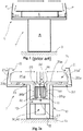
- a refrigerated display table comprises a supporting columnar element, which acts as support base for resting on the ground, and a chest which defines a loading compartment for displaying products and has an enlarged plan section compared to the supporting element.
- the chest C is connected at the top to the supporting element B in correspondence to a bottom portion.
- the loading compartment is delimited at the bottom by the above-mentioned bottom portion and around the perimeter by walls P in transparent material connected to the bottom.
- the table T has a refrigerator circuit comprising at least a condenser (not shown), a compressor (not shown) and an evaporator E.
- the evaporator is arranged in the chest C, placed inside a technical space obtained in the bottom portion by means of a double bottom.
- Such technical space substantially extends over the entire bottom of the chest defining an hollow space for the circulation of air.
- the condenser and the compressor are on the other hand arranged inside the supporting element B.
- the table T is provided with ventilating means (not shown), arranged in the proximity of the evaporator E on the bottom of the chest and suitable for producing a circulation of air affecting the evaporator E and the loading compartment, as indicated by the arrows shown in the figure 1 .
- ventilating means not shown
- US 6412296 B1 discloses a refrigerated cabinet having a chest for displaying goods and a supporting element for the chest.
- the compressor and the condensing unit are placed inside the supporting element, while the evaporator and the ventilating unit are placed in the tank 14, inside a technical compartment for the circulation of the air defined between the bottom of the tank and the loading surface.
- refrigerated display tables are used to create show areas of superior aesthetic standard, e.g., for displaying particular or elegant products.
- the display tables do in fact have a less-imposing structure, which allows the customer to focus greater attention on the products displayed in them.
- the column form of the supporting element, the prevalently horizontal extension of the chest and the use of perimeter walls made of transparent material reduce the visual impact of the unit structure, making it appear slimmer and lighter.
- the need has existed on the market to further accentuate the above aesthetic characteristics.
- the need exists to reduce the thickness of the bottom portion of the chest, so as to better highlight the loading compartment and the products displayed in it, without however negatively affecting the operation of the unit in terms of refrigerating capacity and efficiency.
- object of the present invention is to eliminate the drawbacks of the above-mentioned state of the art, providing a refrigerated display table that can be provided with a chest with bottom portion having reduced thickness without negatively affecting the operation of the unit in terms of refrigerating capacity and efficiency.
- a further object of the present invention is to provide a refrigerated display table that has a superior refrigerating efficiency.
- a further object of the present invention is to provide a refrigerated display table having chest insulation with a more efficient air curtain.
- a further object of the present invention is to provide a refrigerated display table that is easy and inexpensive to make.
- the refrigerated display table comprises a supporting columnar element 10 for resting on the ground G and a chest 20, which is connected at the top to the supporting element 10 in correspondence to a bottom portion 21.
- the chest 20 defines a loading compartment 20a for displaying products by means of a plurality of perimeter walls 29 extending from the bottom portion 21.
- perimeter walls 29 are made of transparent material to reduce the visual impact of the chest and highlight the products placed in the loading compartment 20a.
- the chest 20 has a plan section enlarged with respect to the supporting element 10.
- the refrigerated table 1 has a refrigerating circuit comprising at least a condenser 30, a compressor 40 and an evaporator 50 and ventilating means 60 to produce a circulation of air affecting the evaporator 50 and the chest 20.
- the refrigerating circuit 30, 40 and 50 is completely housed inside the supporting columnar element 10, below the bottom portion 21 of the chest 20.
- the evaporator is no longer arranged inside the chest, but is placed together with the condenser and the compressor inside the supporting element 10.
- the technical volume of the chest dedicated to technical purposes, and therefore subtracted from display purposes can be essentially restricted to the volume needed to create adequate channelling of the air circulating inside the chest.
- the height (or thickness) of the bottom portion can be reduced by reducing the height (or thickness) of the hollow space obtained by means of a double bottom in the bottom portion for the circulation of the air. in fact, unlike the prior art solutions, this hollow space has no longer to house the evaporator.
- the evaporator 50 is positioned directly below the bottom portion 21 of the chest 20. This way, as will be resumed later on, the path of the circulating air is made simpler.
- the evaporator 50 is positioned above the condenser 30 and/or the compressor 40.
- the positioning of the evaporator above at least one of the other two more cumbersome components of the refrigerating circuit permits exploiting the height extension of the supporting columnar element 10. This way, the overall plan dimensions of the supporting element are not increased.
- the inner space of the supporting element is divided into at least two technical spaces: a first technical space indicated by 11, wherein the evaporator 20is housed, and a second technical space, indicated by 12, wherein at least the condenser 30 and the compressor 40 is housed.
- the two technical spaces 11 and 13 are separated by a dividing wall 13, preferably made of heat-insulating material, suitable for preventing heat exchanges between the condenser and the evaporator.
- insulating materials can be used in particular silicone dioxide aerogel, which ensures high performances in terms of insulation with reduced thicknesses.
- the two technical spaces are superimposed the one on the other, with the first technical space 11 arranged above the second technical space 12.
- the evaporator 50 is of the finned type.
- the positioning of the evaporator inside the supporting element 10 allows operating with less restrictive restraints in terms of overall dimensions with respect to prior art solutions.
- a compact type evaporator can be used.
- compact evaporator an evaporator without a preponderant development dimension.
- a compact evaporator is unlike evaporators used in prior art refrigerated tables, which are thin and elongated, designed to be placed on the bottom of the chest and called “flat evaporators”.
- flow area is meant the area orthogonal to the flow of air hitting the evaporator and which crosses it parallel to the heat exchange fins.
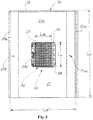
- the reference to the length Lu and to the width La of the flow area Af is given by the dimensions of the chest in length and width.
- compact evaporator can also be meant in particular an evaporator wherein the ratio between the two dimensions chosen between length Lu, width La and height H is not above 3.
- height H is meant the dimension of the evaporator orthogonal to the flow area Af.
- An example of refrigerated table according to the invention envisages a chest 20 having a length Lu' of 1250 mm and a width La' of 1000 mm and a supporting columnar element 10 having a square external section with side of 400 mm and height of 580 mm.
- the supporting element has four adjusting feet which allow lifting the supporting columnar element off the ground by at least 80 mm and at most 230 mm.
- the evaporator has a width La of 350 mm, a length Lu of 260 mm and a height H of 140 mm.
- the chest 20 has an air channelling system to allow the circulation of air inside.
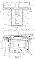
- the channelling system is of the double air supply type, as shown in the Figure 2a and described in detail later on.
- the channelling system can also be of the single supply type, as shown in the Figure 2b .
- the chest 20 may have a double bottom 21a, obtained in the bottom portion 21.
- Such double bottom 21a defines an hollow space 23 for the circulation of air.
- a product supporting grid 21b is positioned above the double bottom 21a.
- the grid 21b is slightly raised with respect to the double bottom 21a so as to create a second hollow space 33 which as will be further explained later facilitates the return of the air to the evaporator and the closing of the air circulation circuit when the chest is filled with products.
- the hollow space 23 communicates directly with the loading compartment 20a of the chest 20 by means of at least two slits 71, 72, which can both be raised with respect to the bottom portion (see Figure 3 ) or one can be raised and one placed level with the bottom (see Figure 2a , first slit 71 and second slit 72 respectively).
- the hollow space 23 substantially covers the entire bottom of the chest.
- the hollow space 23 extends to at least one of the perimeter walls 29 with a first vertical branch 23a' delimited by an inner screen wall 22a (preferably made of transparent material), faced and distanced with respect to one of the perimeter walls 29a.
- Such vertical branch communicates with the loading compartment through the first slit 71.
- the hollow space 23 extends to two perimeter walls 29a and 29b respectively with a first and a second vertical branch 23a' and 23a".
- the second vertical branch 23a" is also delimited by an inner screen wall 22b (preferably made of transparent material), faced and distanced with respect to a second perimeter wall 29b.
- the two vertical branches are made in the chest 20 in opposite positions.
- the second branch 23a" communicates with the loading compartment 20a by means of the second slit 72.
- the two vertical branches 23a' and 23a" act as supply channels for the cold air from the evaporator to the loading compartment 20a.
- both the perimeter walls 29a and 29b, and the inner screen walls 22a and 22b define the two slits 71, 72 by means of extremity portions turned towards the inside of the chest and shaped so as to impress on the flow of air a movement as laminar as possible in order to contrast the natural phenomenon of the heavier cold air dropping downwards.
- the table 1 comprises at least one deflector element 25, 26 arranged in correspondence to the said at least one through opening 24, such deflector element 25, 26 divides the hollow space 23 into a first 23' and into a second sector 23", each communicating with the loading compartment 20a by means of one of the above slits 71, 72.
- the deflector element 25, 26 extends inside the first technical space 11 to delimit:
- the refrigerated table 1 comprises two deflector elements 25, 26 arranged in correspondence to the opening 24 and distanced the one from the other.
- the two deflectors 25, 26 divide the hollow space 23 in the above first 23' and second sector 23", each of which is communicating with the loading compartment 20a by means of one of the above slits 71, 72.
- the two deflectors 25, 26 delimit three ducts in the first technical space 11: the above first duct 27, preferably centred with respect to the opening 24 and comprised between the two deflector elements; and two second ducts 28a and 28b, alongside the first duct 27 in opposite positions, each between a deflector and a portion of perimeter wall of the supporting element 10.
- the evaporator 50 and in particular the finned heat exchange pack, is arranged substantially inside the above first vertical duct 27.
- the first duct 27 places the loading compartment 20a in communication with the evaporator 50, while each second duct 28a and 28b places the first duct 27 in communication with one of the two sectors 23' and 23" of the hollow space 23.
- the ventilating means comprise at least a blower 60 arranged in the proximity of the opening 24.
- the blower 60 is arranged in correspondence to the first duct 27, above the evaporator 50.
- the blower 60 can be placed inside the double bottom 21a or (embodiment not shown) completely outside the bottom portion of the chest 20 and therefore inside the supporting element 10, fastened below to the same bottom portion 21.
- blowers of smaller size can be adopted.
- the blower 60 generates an air flow from the loading compartment 20a towards the evaporator 50 through the first duct 27.
- the flow of cool air leaves the evaporator and rises through the two second ducts 28a and 28b towards the first and the second sectors 23' and 23" respectively of the hollow space and then flows through the respective slits 71, 72 into the loading compartment 20a.
- the two flows of cold air coming from the slits thus create two curtains of cold air that isolate the loading compartment 20a from the outside environment and meet above the opening 24.
- the creation of two air curtains allows considerably improving the heat insulation efficiency compared to the abovementioned prior art solution. As is known, the efficiency of an air curtain increases as its length decreases.
- the refrigerated table 1 comprises a single deflector element 25. Inside the first technical space 11 two ducts are thus delimited: a first duct 27 and a second duct 28a that places in communication the first duct 27 with the first sector 23' of the hollow space 23.
- the second sector 23" of the hollow space 23 instead communicates directly with the opening 24.
- the first sector 23' which includes the first vertical branch 23a' operates under pressure (supply), while the second sector 23" operates in suction (return).
- the blower 60 generates a flow of air from the loading compartment 20a towards the evaporator 50 through the first duct 27. From the loading compartment the air is drawn into the first duct 27 also through the second sector 23". The flow of cooled air leaves the evaporator rising back through the second duct 28a only towards the first sector 23' of the hollow space to then flow through the respective first slit 71 into the loading compartment 20a. The flow of cold air coming from the first slit thus creates a single curtain of cold air which isolates the loading compartment 20a from the outside environment. Part of the cold air returns to the evaporator through the opening 24, while the remaining part (prevented for example by the products present in the chest) returns to the evaporator through the second sector 23" entering through the second slit 72.
- the chest 20 is integrally associated with the supporting columnar element 10, so as to form a single body.
- This solution permits simplifying air channelling, considering that no connections of the mobile type have to be envisaged between the chest and the supporting columnar element.
- the table 1 comprises mobile feet 14 associated with the supporting element 10 to regulate the height and/or the inclination of the chest 20 with respect to the ground G.
- the above mobile feet 14 are associated in sliding manner with guides 15 made on the supporting element 10.
- the supporting columnar element 10 is made with a square-section box body, four feet can be envisaged for example arranged in correspondence to the four corners of the box body.
- the mobile feet 14 are adjustable independently the one from the other.
- the chest 20 is fastened to the supporting columnar element 10 with the bottom portion 21 pre-inclined by an inclination angle ⁇ predefined with respect to a reference plane m orthogonal with respect to a main extension axis x of the supporting columnar element 10.
- main axis x is meant the axis along which the supporting columnar element extends in height.
- the inclination of the chest 20 can be increased or decreased with respect to the ground G, by suitably regulating the position of the feet 14.
- the compressor 40 is installed pre-inclined with respect to the above reference plane m with a predefined pre-inclination angle ⁇ , opposite with respect to the inclination angle ⁇ of the chest 20.
- a predefined pre-inclination angle ⁇ opposite with respect to the inclination angle ⁇ of the chest 20.
- the two angles ⁇ and ⁇ have the same amplitude.
- the compressors normally used in refrigerated counters must be installed within specific inclination ranges to be able to operate correctly. Thanks to the opposite pre-inclination of the compressor with respect to the chest, the chest can be inclined and with this the supporting columnar element (integral with the chest) beyond the maximum inclination angles allowed for the compressor.
- the chest is made pre-inclined with respect to the supporting element by 3° in the opposite direction ( Figure 5 ).
- the feet By suitably regulating the feet it is still possible to increase the inclination of the chest by another 6°.
- the compressor With an increase of just 3° of inclination, the compressor is in fact horizontal ( Figure 6 ), while with an increase of 6° the compressor reaches maximum allowed inclination ( Figure 7 ) in the opposite direction with respect to the initial one.
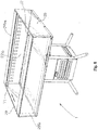
- the refrigerated display table 1 is ideal for use as a modular element for the creation of extensive display areas. Thanks to the mobile feet, the height and the inclination of each single module 1' and 1" can be adjusted so as to create a single display table.
- the invention allows obtaining numerous advantages in part already described.
- the refrigerated display table according to the invention can be provided with a chest with bottom of reduced thickness without affecting the operation of the unit in terms of refrigerating capacity and efficiency.
- an evaporator of the compact type can be adopted, thereby considerably improving the efficiency of the refrigerating system.
- the air curtain can be split into two, improving the efficiency of the heat insulation.
Landscapes
- Physics & Mathematics (AREA)
- Thermal Sciences (AREA)
- Freezers Or Refrigerated Showcases (AREA)
Claims (17)
- Étal réfrigéré comprenant :- un élément colonnaire de support (10) destiné à reposer sur le sol (G) ;- un coffre (20), relié à la partie supérieure dudit élément de support (10) en correspondance avec une partie inférieure (21), et définissant un compartiment de chargement (20a) pour exposer des produits au moyen d'une pluralité de parois périphériques (29) s'étendant à partir de ladite partie inférieure (21), ledit coffre (20) ayant un double fond (21a), réalisé dans ladite partie inférieure (21), qui délimite un espace creux (23) pour la circulation de l'air, ledit coffre ayant une section en plan élargie par rapport audit élément de support (10) ;- un circuit réfrigérant comprenant au moins un condensateur (30), un compresseur (40) et un évaporateur (50) ;- des moyens de ventilation (60) pour générer une circulation d'air affectant ledit évaporateur (50) et ledit coffre (20), caractérisé en ce que ledit circuit réfrigérant (30, 40, 50) est logé complètement à l'intérieur dudit élément colonnaire de support (10) en dessous de la partie inférieure (21) dudit coffre (20) de sorte à réduire le volume du coffre dédié à des fins de non-exposition.
- Étal réfrigéré selon la revendication 1, dans lequel ledit évaporateur (50) est positionné directement en dessous de la partie inférieure (21) dudit coffre (20).
- Étal réfrigéré selon la revendication 1 ou 2, dans lequel ledit évaporateur (50) est positionné au-dessus dudit condensateur (30) et/ou dudit compresseur (40).
- Étal réfrigéré selon une ou plusieurs des revendications précédentes, dans lequel ledit évaporateur (50) est un évaporateur du type compact.
- Étal réfrigéré selon une ou plusieurs des revendications précédentes, dans lequel l'espace interne dudit élément de support (10) est divisé en au moins un premier espace technique (11), dans lequel est logé l'évaporateur (20), et un second espace technique (12), dans lequel est logé au moins le condensateur (30) et/ou au moins le compresseur (40), ledit étal comprenant au moins une paroi de séparation (13) agencée entre lesdits deux espaces techniques (11, 12), de préférence constituée de matériau thermo-isolant.
- Étal réfrigéré selon une ou plusieurs des revendications précédentes, dans lequel ledit coffre (20) a un double fond (21a), réalisé dans ladite partie inférieure (21) qui délimite un espace creux (23) pour la circulation de l'air, ledit espace creux (23) communiquant directement avec le compartiment de chargement (20a) dudit coffre (20) au moyen d'au moins deux fentes (71, 72).
- Étal réfrigéré selon la revendication précédente, dans lequel ledit espace creux (23) s'étend vers au moins l'une desdites parois périphériques (29) avec une première ramification verticale (23a'), qui est délimitée par au moins une paroi écran interne (22a, 22b) faisant face et à distance de l'une desdites parois périphériques (29) et communique avec ledit compartiment de chargement à travers une première fente (71).
- Étal réfrigéré selon la revendication 6 ou 7, dans lequel en correspondance avec l'élément de support (10), au moins une ouverture traversante (24) est réalisée sur ladite partie inférieure (21), ladite ouverture plaçant ledit coffre (20) en communication directe avec ledit premier espace technique (11).
- Étal réfrigéré selon la revendication 8, comprenant au moins un élément déflecteur (25, 26) qui est placé en correspondance avec ladite au moins une ouverture (24) et divise ledit espace creux (23) en un premier (23') et un second secteur (23"), chaque secteur communiquant avec ledit compartiment de chargement (20a) à travers l'une desdites fentes (71, 72), ledit au moins un déflecteur (25, 26) s'étendant à l'intérieur dudit premier espace technique (11) pour délimiter :- un premier conduit (27), dans lequel ledit évaporateur (50) est au moins partiellement logé et qui place le compartiment de chargement (10a) en communication directe avec ledit premier espace technique ; et- au moins un second conduit (28a, 28b), qui place ledit premier conduit (27) en communication avec le premier secteur (23') dudit espace creux (23).
- Étal réfrigéré selon la revendication 9, comprenant deux éléments déflecteurs (25, 26) qui délimitent deux seconds conduits (28a, 28b), séparés par ledit premier conduit (27), chacun desdits seconds conduits plaçant ledit premier conduit (27) en communication avec l'un des deux secteurs (23', 23") dudit espace creux (23).
- Étal réfrigéré selon la revendication 9, dans lequel le second secteur (23") dudit espace creux (23) communique directement avec ladite ouverture (24).
- Étal réfrigéré selon l'une quelconque des revendications 8 à 11, dans lequel lesdits moyens de ventilation comprennent au moins un ventilateur (60) positionné à proximité de ladite première ouverture, de préférence en correspondance avec ledit premier conduit (27).
- Étal réfrigéré selon une ou plusieurs des revendications précédentes, dans lequel ledit coffre (20) est associé d'un seul tenant avec ledit élément colonnaire de support (10).
- Étal réfrigéré selon la revendication 13, comprenant des pieds mobiles (14) associés avec ledit élément de support (10) pour régler la hauteur et/ou l'inclinaison dudit coffre (20) par rapport au sol.
- Étal réfrigéré selon la revendication 14, dans lequel lesdits pieds mobiles (14) sont associés d'une manière coulissante avec des guides (15) réalisés sur ledit élément de support (10), lesdits pieds (14) étant de préférence réglables indépendamment l'un de l'autre.
- Étal réfrigéré selon une ou plusieurs des revendications 13, 14 ou 15, dans lequel la partie inférieure (21) dudit coffre est inclinée selon un angle d'inclinaison (α) prédéfini, par rapport à un plan de référence horizontal (m), orthogonal par rapport à un axe d'extension principal (x) dudit élément colonnaire de support (10).
- Étal réfrigéré selon la revendication précédente, dans lequel ledit compresseur (40) est installé de manière inclinée par rapport audit plan de référence (m) selon un angle de pré-inclinaison (β) prédéterminé, opposé par rapport à l'angle d'inclinaison (α) dudit coffre (20), lesdits deux angles (α, β) ayant de préférence la même amplitude.
Priority Applications (1)
| Application Number | Priority Date | Filing Date | Title |
|---|---|---|---|
| EP10425217.6A EP2399487B1 (fr) | 2010-06-25 | 2010-06-25 | Etal réfrigéré |
Applications Claiming Priority (1)
| Application Number | Priority Date | Filing Date | Title |
|---|---|---|---|
| EP10425217.6A EP2399487B1 (fr) | 2010-06-25 | 2010-06-25 | Etal réfrigéré |
Publications (2)
| Publication Number | Publication Date |
|---|---|
| EP2399487A1 EP2399487A1 (fr) | 2011-12-28 |
| EP2399487B1 true EP2399487B1 (fr) | 2018-03-14 |
Family
ID=42990241
Family Applications (1)
| Application Number | Title | Priority Date | Filing Date |
|---|---|---|---|
| EP10425217.6A Not-in-force EP2399487B1 (fr) | 2010-06-25 | 2010-06-25 | Etal réfrigéré |
Country Status (1)
| Country | Link |
|---|---|
| EP (1) | EP2399487B1 (fr) |
Families Citing this family (1)
| Publication number | Priority date | Publication date | Assignee | Title |
|---|---|---|---|---|
| CN115462658B (zh) * | 2022-09-14 | 2024-06-21 | 江苏星星冷链科技有限公司 | 一种双循环风冷卧式冷冻展示柜 |
Family Cites Families (3)
| Publication number | Priority date | Publication date | Assignee | Title |
|---|---|---|---|---|
| US6412296B1 (en) * | 1999-02-19 | 2002-07-02 | Isa Spa | Device to distribute air in glass-fronted cabinets and display counters |
| DE10130928A1 (de) * | 2001-06-27 | 2003-01-16 | Linde Ag | Kühltheke mit mehreren Warenpräsentationsebenen |
| DE202009013280U1 (de) * | 2009-10-02 | 2010-03-11 | Carrier Corp., Farmington | Verkaufskühlmöbel mit Nachtabdeckung |
-
2010
- 2010-06-25 EP EP10425217.6A patent/EP2399487B1/fr not_active Not-in-force
Non-Patent Citations (1)
| Title |
|---|
| None * |
Also Published As
| Publication number | Publication date |
|---|---|
| EP2399487A1 (fr) | 2011-12-28 |
Similar Documents
| Publication | Publication Date | Title |
|---|---|---|
| US9775448B2 (en) | Refrigerated display appliances | |
| US8863541B2 (en) | Air distribution system for temperature-controlled case | |
| US7243506B2 (en) | Air blanketed food preparation table | |
| JP5556208B2 (ja) | ショーケース | |
| EP3481260B1 (fr) | Meuble d'exposition réfrigéré | |
| EP3474706B1 (fr) | Unité de présentation pour le stockage et la présentation de produits chauffés, et utilisation d'une unité de présentation | |
| EP2399487B1 (fr) | Etal réfrigéré | |
| CN107314594B (zh) | 一种风幕的风量分流结构 | |
| GB2370876A (en) | Air deflecting shelf for a refrigerated cabinet | |
| JP2880464B2 (ja) | アラウンドショーケース | |
| CN207262783U (zh) | 一种风幕的风量分流结构 | |
| JP4923972B2 (ja) | ショーケース | |
| US20240324794A1 (en) | Refrigerated merchandiser with tunable airflow discharge | |
| JP2008000535A (ja) | ショーケース | |
| JP7165905B2 (ja) | ショーケース | |
| WO2012145136A1 (fr) | Enceinte de présentation réfrigérée à îlots | |
| JP2015150042A (ja) | オープンショーケース | |
| AU6356201A (en) | An improved refrigerator shelf |
Legal Events
| Date | Code | Title | Description |
|---|---|---|---|
| AK | Designated contracting states |
Kind code of ref document: A1 Designated state(s): AL AT BE BG CH CY CZ DE DK EE ES FI FR GB GR HR HU IE IS IT LI LT LU LV MC MK MT NL NO PL PT RO SE SI SK SM TR |
|
| AX | Request for extension of the european patent |
Extension state: BA ME RS |
|
| PUAI | Public reference made under article 153(3) epc to a published international application that has entered the european phase |
Free format text: ORIGINAL CODE: 0009012 |
|
| 17P | Request for examination filed |
Effective date: 20120611 |
|
| GRAP | Despatch of communication of intention to grant a patent |
Free format text: ORIGINAL CODE: EPIDOSNIGR1 |
|
| INTG | Intention to grant announced |
Effective date: 20171011 |
|
| GRAS | Grant fee paid |
Free format text: ORIGINAL CODE: EPIDOSNIGR3 |
|
| GRAA | (expected) grant |
Free format text: ORIGINAL CODE: 0009210 |
|
| AK | Designated contracting states |
Kind code of ref document: B1 Designated state(s): AL AT BE BG CH CY CZ DE DK EE ES FI FR GB GR HR HU IE IS IT LI LT LU LV MC MK MT NL NO PL PT RO SE SI SK SM TR |
|
| REG | Reference to a national code |
Ref country code: GB Ref legal event code: FG4D |
|
| REG | Reference to a national code |
Ref country code: CH Ref legal event code: EP Ref country code: AT Ref legal event code: REF Ref document number: 978028 Country of ref document: AT Kind code of ref document: T Effective date: 20180315 |
|
| REG | Reference to a national code |
Ref country code: IE Ref legal event code: FG4D |
|
| REG | Reference to a national code |
Ref country code: DE Ref legal event code: R096 Ref document number: 602010049150 Country of ref document: DE |
|
| REG | Reference to a national code |
Ref country code: FR Ref legal event code: PLFP Year of fee payment: 9 |
|
| REG | Reference to a national code |
Ref country code: NL Ref legal event code: MP Effective date: 20180314 |
|
| REG | Reference to a national code |
Ref country code: LT Ref legal event code: MG4D |
|
| PG25 | Lapsed in a contracting state [announced via postgrant information from national office to epo] |
Ref country code: FI Free format text: LAPSE BECAUSE OF FAILURE TO SUBMIT A TRANSLATION OF THE DESCRIPTION OR TO PAY THE FEE WITHIN THE PRESCRIBED TIME-LIMIT Effective date: 20180314 Ref country code: NO Free format text: LAPSE BECAUSE OF FAILURE TO SUBMIT A TRANSLATION OF THE DESCRIPTION OR TO PAY THE FEE WITHIN THE PRESCRIBED TIME-LIMIT Effective date: 20180614 Ref country code: CY Free format text: LAPSE BECAUSE OF FAILURE TO SUBMIT A TRANSLATION OF THE DESCRIPTION OR TO PAY THE FEE WITHIN THE PRESCRIBED TIME-LIMIT Effective date: 20180314 Ref country code: LT Free format text: LAPSE BECAUSE OF FAILURE TO SUBMIT A TRANSLATION OF THE DESCRIPTION OR TO PAY THE FEE WITHIN THE PRESCRIBED TIME-LIMIT Effective date: 20180314 Ref country code: HR Free format text: LAPSE BECAUSE OF FAILURE TO SUBMIT A TRANSLATION OF THE DESCRIPTION OR TO PAY THE FEE WITHIN THE PRESCRIBED TIME-LIMIT Effective date: 20180314 Ref country code: ES Free format text: LAPSE BECAUSE OF FAILURE TO SUBMIT A TRANSLATION OF THE DESCRIPTION OR TO PAY THE FEE WITHIN THE PRESCRIBED TIME-LIMIT Effective date: 20180314 |
|
| REG | Reference to a national code |
Ref country code: AT Ref legal event code: MK05 Ref document number: 978028 Country of ref document: AT Kind code of ref document: T Effective date: 20180314 |
|
| PG25 | Lapsed in a contracting state [announced via postgrant information from national office to epo] |
Ref country code: GR Free format text: LAPSE BECAUSE OF FAILURE TO SUBMIT A TRANSLATION OF THE DESCRIPTION OR TO PAY THE FEE WITHIN THE PRESCRIBED TIME-LIMIT Effective date: 20180615 Ref country code: BG Free format text: LAPSE BECAUSE OF FAILURE TO SUBMIT A TRANSLATION OF THE DESCRIPTION OR TO PAY THE FEE WITHIN THE PRESCRIBED TIME-LIMIT Effective date: 20180614 Ref country code: LV Free format text: LAPSE BECAUSE OF FAILURE TO SUBMIT A TRANSLATION OF THE DESCRIPTION OR TO PAY THE FEE WITHIN THE PRESCRIBED TIME-LIMIT Effective date: 20180314 Ref country code: SE Free format text: LAPSE BECAUSE OF FAILURE TO SUBMIT A TRANSLATION OF THE DESCRIPTION OR TO PAY THE FEE WITHIN THE PRESCRIBED TIME-LIMIT Effective date: 20180314 |
|
| PG25 | Lapsed in a contracting state [announced via postgrant information from national office to epo] |
Ref country code: PL Free format text: LAPSE BECAUSE OF FAILURE TO SUBMIT A TRANSLATION OF THE DESCRIPTION OR TO PAY THE FEE WITHIN THE PRESCRIBED TIME-LIMIT Effective date: 20180314 Ref country code: EE Free format text: LAPSE BECAUSE OF FAILURE TO SUBMIT A TRANSLATION OF THE DESCRIPTION OR TO PAY THE FEE WITHIN THE PRESCRIBED TIME-LIMIT Effective date: 20180314 Ref country code: NL Free format text: LAPSE BECAUSE OF FAILURE TO SUBMIT A TRANSLATION OF THE DESCRIPTION OR TO PAY THE FEE WITHIN THE PRESCRIBED TIME-LIMIT Effective date: 20180314 Ref country code: RO Free format text: LAPSE BECAUSE OF FAILURE TO SUBMIT A TRANSLATION OF THE DESCRIPTION OR TO PAY THE FEE WITHIN THE PRESCRIBED TIME-LIMIT Effective date: 20180314 Ref country code: AL Free format text: LAPSE BECAUSE OF FAILURE TO SUBMIT A TRANSLATION OF THE DESCRIPTION OR TO PAY THE FEE WITHIN THE PRESCRIBED TIME-LIMIT Effective date: 20180314 |
|
| PG25 | Lapsed in a contracting state [announced via postgrant information from national office to epo] |
Ref country code: SK Free format text: LAPSE BECAUSE OF FAILURE TO SUBMIT A TRANSLATION OF THE DESCRIPTION OR TO PAY THE FEE WITHIN THE PRESCRIBED TIME-LIMIT Effective date: 20180314 Ref country code: SM Free format text: LAPSE BECAUSE OF FAILURE TO SUBMIT A TRANSLATION OF THE DESCRIPTION OR TO PAY THE FEE WITHIN THE PRESCRIBED TIME-LIMIT Effective date: 20180314 Ref country code: AT Free format text: LAPSE BECAUSE OF FAILURE TO SUBMIT A TRANSLATION OF THE DESCRIPTION OR TO PAY THE FEE WITHIN THE PRESCRIBED TIME-LIMIT Effective date: 20180314 Ref country code: CZ Free format text: LAPSE BECAUSE OF FAILURE TO SUBMIT A TRANSLATION OF THE DESCRIPTION OR TO PAY THE FEE WITHIN THE PRESCRIBED TIME-LIMIT Effective date: 20180314 |
|
| REG | Reference to a national code |
Ref country code: DE Ref legal event code: R097 Ref document number: 602010049150 Country of ref document: DE |
|
| PG25 | Lapsed in a contracting state [announced via postgrant information from national office to epo] |
Ref country code: PT Free format text: LAPSE BECAUSE OF FAILURE TO SUBMIT A TRANSLATION OF THE DESCRIPTION OR TO PAY THE FEE WITHIN THE PRESCRIBED TIME-LIMIT Effective date: 20180716 |
|
| PLBE | No opposition filed within time limit |
Free format text: ORIGINAL CODE: 0009261 |
|
| STAA | Information on the status of an ep patent application or granted ep patent |
Free format text: STATUS: NO OPPOSITION FILED WITHIN TIME LIMIT |
|
| PG25 | Lapsed in a contracting state [announced via postgrant information from national office to epo] |
Ref country code: DK Free format text: LAPSE BECAUSE OF FAILURE TO SUBMIT A TRANSLATION OF THE DESCRIPTION OR TO PAY THE FEE WITHIN THE PRESCRIBED TIME-LIMIT Effective date: 20180314 |
|
| REG | Reference to a national code |
Ref country code: CH Ref legal event code: PL |
|
| 26N | No opposition filed |
Effective date: 20181217 |
|
| PG25 | Lapsed in a contracting state [announced via postgrant information from national office to epo] |
Ref country code: SI Free format text: LAPSE BECAUSE OF FAILURE TO SUBMIT A TRANSLATION OF THE DESCRIPTION OR TO PAY THE FEE WITHIN THE PRESCRIBED TIME-LIMIT Effective date: 20180314 |
|
| REG | Reference to a national code |
Ref country code: BE Ref legal event code: MM Effective date: 20180630 |
|
| REG | Reference to a national code |
Ref country code: IE Ref legal event code: MM4A |
|
| PG25 | Lapsed in a contracting state [announced via postgrant information from national office to epo] |
Ref country code: MC Free format text: LAPSE BECAUSE OF FAILURE TO SUBMIT A TRANSLATION OF THE DESCRIPTION OR TO PAY THE FEE WITHIN THE PRESCRIBED TIME-LIMIT Effective date: 20180314 Ref country code: LU Free format text: LAPSE BECAUSE OF NON-PAYMENT OF DUE FEES Effective date: 20180625 |
|
| PG25 | Lapsed in a contracting state [announced via postgrant information from national office to epo] |
Ref country code: CH Free format text: LAPSE BECAUSE OF NON-PAYMENT OF DUE FEES Effective date: 20180630 Ref country code: IE Free format text: LAPSE BECAUSE OF NON-PAYMENT OF DUE FEES Effective date: 20180625 Ref country code: LI Free format text: LAPSE BECAUSE OF NON-PAYMENT OF DUE FEES Effective date: 20180630 |
|
| PG25 | Lapsed in a contracting state [announced via postgrant information from national office to epo] |
Ref country code: BE Free format text: LAPSE BECAUSE OF NON-PAYMENT OF DUE FEES Effective date: 20180630 |
|
| PG25 | Lapsed in a contracting state [announced via postgrant information from national office to epo] |
Ref country code: MT Free format text: LAPSE BECAUSE OF NON-PAYMENT OF DUE FEES Effective date: 20180625 |
|
| PG25 | Lapsed in a contracting state [announced via postgrant information from national office to epo] |
Ref country code: TR Free format text: LAPSE BECAUSE OF FAILURE TO SUBMIT A TRANSLATION OF THE DESCRIPTION OR TO PAY THE FEE WITHIN THE PRESCRIBED TIME-LIMIT Effective date: 20180314 |
|
| PG25 | Lapsed in a contracting state [announced via postgrant information from national office to epo] |
Ref country code: HU Free format text: LAPSE BECAUSE OF FAILURE TO SUBMIT A TRANSLATION OF THE DESCRIPTION OR TO PAY THE FEE WITHIN THE PRESCRIBED TIME-LIMIT; INVALID AB INITIO Effective date: 20100625 |
|
| PG25 | Lapsed in a contracting state [announced via postgrant information from national office to epo] |
Ref country code: MK Free format text: LAPSE BECAUSE OF NON-PAYMENT OF DUE FEES Effective date: 20180314 |
|
| PG25 | Lapsed in a contracting state [announced via postgrant information from national office to epo] |
Ref country code: IS Free format text: LAPSE BECAUSE OF FAILURE TO SUBMIT A TRANSLATION OF THE DESCRIPTION OR TO PAY THE FEE WITHIN THE PRESCRIBED TIME-LIMIT Effective date: 20180714 |
|
| PGFP | Annual fee paid to national office [announced via postgrant information from national office to epo] |
Ref country code: IT Payment date: 20230419 Year of fee payment: 14 Ref country code: FR Payment date: 20230622 Year of fee payment: 14 Ref country code: DE Payment date: 20230620 Year of fee payment: 14 |
|
| PGFP | Annual fee paid to national office [announced via postgrant information from national office to epo] |
Ref country code: GB Payment date: 20230622 Year of fee payment: 14 |
|
| REG | Reference to a national code |
Ref country code: DE Ref legal event code: R119 Ref document number: 602010049150 Country of ref document: DE |
|
| GBPC | Gb: european patent ceased through non-payment of renewal fee |
Effective date: 20240625 |
|
| PG25 | Lapsed in a contracting state [announced via postgrant information from national office to epo] |
Ref country code: DE Free format text: LAPSE BECAUSE OF NON-PAYMENT OF DUE FEES Effective date: 20250101 |
|
| PG25 | Lapsed in a contracting state [announced via postgrant information from national office to epo] |
Ref country code: FR Free format text: LAPSE BECAUSE OF NON-PAYMENT OF DUE FEES Effective date: 20240630 |
|
| PG25 | Lapsed in a contracting state [announced via postgrant information from national office to epo] |
Ref country code: IT Free format text: LAPSE BECAUSE OF NON-PAYMENT OF DUE FEES Effective date: 20240625 Ref country code: GB Free format text: LAPSE BECAUSE OF NON-PAYMENT OF DUE FEES Effective date: 20240625 |