EP3481260B1 - Meuble d'exposition réfrigéré - Google Patents
Meuble d'exposition réfrigéré Download PDFInfo
- Publication number
- EP3481260B1 EP3481260B1 EP17757872.1A EP17757872A EP3481260B1 EP 3481260 B1 EP3481260 B1 EP 3481260B1 EP 17757872 A EP17757872 A EP 17757872A EP 3481260 B1 EP3481260 B1 EP 3481260B1
- Authority
- EP
- European Patent Office
- Prior art keywords
- refrigerated
- shelves
- delivery duct
- air
- display cabinet
- Prior art date
- Legal status (The legal status is an assumption and is not a legal conclusion. Google has not performed a legal analysis and makes no representation as to the accuracy of the status listed.)
- Active
Links
Images


Classifications
-
- A—HUMAN NECESSITIES
- A47—FURNITURE; DOMESTIC ARTICLES OR APPLIANCES; COFFEE MILLS; SPICE MILLS; SUCTION CLEANERS IN GENERAL
- A47F—SPECIAL FURNITURE, FITTINGS, OR ACCESSORIES FOR SHOPS, STOREHOUSES, BARS, RESTAURANTS OR THE LIKE; PAYING COUNTERS
- A47F3/00—Show cases or show cabinets
- A47F3/04—Show cases or show cabinets air-conditioned, refrigerated
- A47F3/0439—Cases or cabinets of the open type
- A47F3/0443—Cases or cabinets of the open type with forced air circulation
- A47F3/0456—Cases or cabinets of the counter type
-
- A—HUMAN NECESSITIES
- A47—FURNITURE; DOMESTIC ARTICLES OR APPLIANCES; COFFEE MILLS; SPICE MILLS; SUCTION CLEANERS IN GENERAL
- A47F—SPECIAL FURNITURE, FITTINGS, OR ACCESSORIES FOR SHOPS, STOREHOUSES, BARS, RESTAURANTS OR THE LIKE; PAYING COUNTERS
- A47F3/00—Show cases or show cabinets
- A47F3/04—Show cases or show cabinets air-conditioned, refrigerated
- A47F3/0439—Cases or cabinets of the open type
- A47F3/0443—Cases or cabinets of the open type with forced air circulation
- A47F2003/046—Cases or cabinets of the open type with forced air circulation with shelves having air ducts
Definitions
- the present invention refers in general to a refrigerated display cabinet and, in particular, to a refrigerated display cabinet that combines the characteristics both of a refrigerated display cabinet of the so-called wall-mounted type, and of a refrigerated display cabinet of the so-called island type.
- refrigerated cabinets for displaying consumer products
- refrigerated display groups or refrigerated cabinets
- These refrigerated display groups, or refrigerated cabinets are typically used in the field of mass distribution to display and conserve particular types of perishable products.
- these refrigerated display cabinets are often used in supermarkets, canteens, etc. to offer the possibility of purchasing fresh products and of keeping the products themselves in an environment at a suitable temperature.
- WO 2008/074355 A1 discloses a refrigerating cabinet used in supermarkets, comprising a display case defining a display space, at least one shelf arranged in the display case for bearing of goods requiring refrigeration.
- refrigerated cabinets can be divided into:
- Each type of refrigerated cabinet has its own functional characteristics that are often different from those of other types of refrigerated cabinets.
- each type of refrigerated cabinet has its own advantages and defects.
- an island cabinet can occupy more floor space with respect to a wall-mounted cabinet for the same refrigerated volume and/or amount of goods displayed.
- an island cabinet can have better accessibility to the products contained in it with respect to a wall-mounted cabinet, the upper shelves of which for storing products are often arranged at great heights from the ground.
- the general purpose of the present invention is therefore that of making a refrigerated display cabinet, in particular a refrigerated display cabinet of the combined type, which is capable of overcoming the aforementioned drawbacks of the prior art in an extremely simple, cost-effective and particularly functional manner.
- a purpose of the present invention is to make a refrigerated display cabinet that is capable of combining the characteristics typical of wall-mounted and island refrigerated cabinets, improving the ergonomics, in terms of visibility and accessibility of the displayed products, with respect to known refrigerated cabinets.
- Another purpose of the invention is to make a refrigerated display cabinet that is capable of optimising the floor space occupied, in other words increasing the amount of goods displayed for the same floor space occupied, with respect to known refrigerated cabinets.
- the refrigerated display cabinet according to the present invention combines the typical characteristics of wall-mounted and island refrigerated cabinets, making it possible to house the products both on an upper shelf accessible from above, typical of an island cabinet, and on a plurality of display surfaces extending horizontally accessible from the front, characteristics of a wall-mounted cabinet.
- the refrigerated display cabinet according to the present invention makes it possible to obtain high ergonomics, in terms of visibility and accessibility of the displayed products, together with the optimisation of the floor space occupied.
- the refrigerated display cabinet according to the present invention has particularly small dimensions in plan, which provide great versatility.
- the floor space occupied is indeed intended, on the one hand, to satisfy the requirement of low space occupied demanded by the market and, on the other hand, to ensure the possibility of combining and channelling, in a modular fashion, many refrigerated display cabinets.
- the vertical extension of the refrigerated display cabinet also makes it possible to obtain one or more further display levels, thanks to which the amount of goods displayed, for the same floor space occupied, is considerably increased.
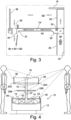
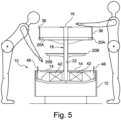
- a refrigerated display cabinet according to the present invention is shown, wholly indicated with reference numeral 10.
- the refrigerated display cabinet 10 is provided with at least one refrigerating machine (not shown) which can be both incorporated in the refrigerated display cabinet 10 itself, and installed remotely to be able to operate with a plurality of distinct refrigerated display groups.
- the refrigerated display cabinet 10 is thus provided with a base block 12 in which at least one display surface 14 is formed, intended to contain a plurality of products to be kept at a temperature below room temperature by means of the refrigerating machine.
- each display surface 14 extends mainly horizontally, typical of island refrigerated display cabinets, and can be provided with one or more vertical dividing walls (not shown).
- Each shelf 20A and 20B is arranged at a greater height with respect to the height of each display surface 14 with reference to a support plane of the base block 12.
- two distinct batteries of shelves 20A and 20B are provided, arranged above each display surface 14 at two respective predetermined heights from the support plane of the base block 12.
- one or more upper shelves 20A can be provided, preferably delimited by respective front partitions 36, and possibly one or more lower shelves 20B, arranged between each display surface 14 and such upper shelves 20A.
- each delivery duct 22 and 24 is configured to convey refrigerated air, produced by the refrigerating machine, towards each display surface 14 and towards each shelf 20A and 20B.
- at least one main delivery duct 22, obtained inside the support structure 18, and at least one secondary delivery duct 24, obtained inside at least part of the shelves 20A and 20B and arranged in fluid connection downstream of the main delivery duct 22 are provided.
- Each main delivery duct 22 extends mainly vertically, whereas each secondary delivery duct 24 extends mainly horizontally, being associated with a respective shelf 20A and 20B extending horizontally, in this case the upper shelves 20A. Moreover, each main delivery duct 22 has an average passage cross section of the refrigerated air that is greater than the average passage cross section of the refrigerated air of each secondary delivery duct 24.
- each main delivery duct 22 Along the vertical side surface of each main delivery duct 22 there is a plurality of slots 26 oriented to send the refrigerated air towards each display surface 14 and towards at least part of the shelves 20A and 20B.
- at least one selective deflector 30 is arranged, configured to divide the flow of refrigerated air into two distinct flows, as will be specified better hereinafter.
- each secondary delivery duct 24 extends along a direction substantially perpendicular to the direction of extension of the respective secondary delivery duct 24.
- the respective end opening portion 32 extends vertically downwards to convey at least part of the refrigerated air towards each display surface 14 and towards possible lower shelves 20B arranged below such a secondary delivery duct 24.
- each end opening portion 32 has an average passage cross section of the refrigerated air that is smaller than the average passage cross section of the refrigerated air of the respective secondary delivery duct 24.
- the operation of the refrigerated display cabinet 10 is thus based on a single a Vogellic circuit that simultaneously cools both each display surface 14, and each shelf 20A and 20B above.
- the refrigerated display cabinet 10 is symmetrical with respect to a vertical plane passing through the support structure 18 of the shelves 20A and 20B.
- one or more shelves 20A and 20B are provided arranged on one side of the refrigerated display cabinet 10 and one or more corresponding shelves 20A and 20B are provided arranged on the opposite side of such a refrigerated display cabinet 10. It is thus possible to provide one or more main delivery ducts 22, parallel to one another, which extend vertically inside the support structure 18.
- the single aeraulic circuit based mainly on the shape of dividing walls and deflectors and on the suitable sizing of the delivery ducts 22 and 24, makes it possible to suck suction air from the upper shelves 20A without the help of additional machines or tools, keeping the aeraulic circuit equally closed and stable. Thanks to the aforementioned system, the two different types of refrigerated cabinet, island and wall-mounted, can co-exist in a single body.
- All of the apparatuses (heat exchangers, fans and valves) of the refrigerating machine necessary to keep the aeraulic circuit in normal operating conditions are housed in one or more suitable compartments 42 arranged inside the base block 12. These apparatuses, enclosed in the respective compartments 42, have identical operation to that of the corresponding apparatuses of a conventional refrigerated cabinet.
- a first portion of air flow rate Q v at delivery temperature is drawn through the slots 26 to cool the products contained on the display surfaces 14.
- a second portion of air flow rate Q r at delivery temperature is, on the other hand, intended for cooling the goods present on the lower shelves 20B.
- the remaining air flow rate is driven to each selective deflector 30 positioned at the base of a respective upper shelf 20A.
- the selective deflector 30 is suitably perforated and shaped to further divide the air flow rate Q f in two distinct air flow rates Q 1 and Q 2 .
- a first air flow rate Q 1 is channelled in every single secondary horizontal delivery duct 24 obtained inside the respective upper shelves 20A. Inside the horizontal secondary delivery duct 24 the air flow rate Q 1 undergoes an acceleration, due to the narrowing of the section of such a secondary delivery duct 24 with respect to the main delivery ducts 22. Crossing a closed channel, the thermal load of the air flow rate Q 1 only undergoes negligible losses. Consequently, once the end opening portion 32 of each secondary delivery duct 24 is reached, the air flow rate Q 1 can be considered at delivery temperature.
- the air flow rate Q 1 is forced to a second acceleration by a further narrowing of the passage section. At the end opening portion 32, therefore, the air flow rate Q 1 is deviated downwards and directed towards a suction grid 34 of each display surface 14, thus acting as an air curtain for the wall part of the refrigerated display cabinet 10.
- the second air flow rate Q 2 is pushed upwards inside each upper main delivery duct 22.
- a precise sizing of the upper slots 26 allows this second air flow rate Q 2 to come out above the upper shelves 20A.
- the temperature of the second air flow rate Q 2 is always that of delivery. Due to the braking effect of the selective deflector 30, combined with that of the slots system 26, the second air flow rate Q2 is less, not only in terms of flow rate but also as kinetic energy, with respect to the air flow rate Q 1 that flows parallel in the secondary delivery duct 24 below, but remaining sufficient to adequately conserve the displayed goods.
- each upper shelf 20A At the free end of each upper shelf 20A the air flow rate Q 2 has absorbed the thermal load of the goods, going to the suction temperature, and reaches a front partition 36, preferably transparent.
- the front partition 36 extends vertically and is fixedly connected to a respective upper shelf 20A at the end opening portion 32 of the respective secondary delivery duct 24.
- a suction channel 38 extending vertically is arranged between each upper shelf 20A and the respective front partition 36. The air flow rate Q 2 , deviated by the front partition 36, is thus sent above the suction channel 38.
- the suction channel 38 is separated from the end opening portion 32 through a dividing wall 40 of minimal thickness.
- the air flow rate Q 1 greater with respect to the air flow rate Q 2 , comes out from the end opening portion 32 at high speed.
- the kinetic energy of the air flow rate Q 1 thus generates a natural driving force close to its limit. Keeping the suction channel 38 a minimum distance from the end opening portion 32 makes it possible to subject the air flow rate Q 2 to the aforementioned driving force.
- the resulting effect is the sucking of the air flow rate Q 2 , which is sucked through the suction channel 38 and mixes with the air flow rate Q 1 , which drives it downwards.
- the kinetic load of the air flow rate Q 1 is regulated by the shape of the selective deflector 30, by the size of the section of the secondary delivery duct 24 and by the size of the end opening portion 32, so as to be sufficient to capture the air flow rate Q 2 and still conserve the energy to constitute a curtain of air suitable for the refrigeration of the lower shelves 20B.
- the ratio in dimensional terms between the air flow rates Q 1 and Q 2 is regulated by the shape of the selective deflector 30, so that the air flow rate Q 1 is much greater than the air flow rate Q 2 , in the limits to in any case ensure the refrigerating effect of such an air flow rate Q 2 .
- the thermal impact due to the mixing of the air flow rate Q 2 , at suction temperature, with the air flow rate Q 1 , at delivery temperature is reduced.
- the resulting air flow rate Q c which forms a downward curtain, joins with the air flow rates Q r and Q v , which respectively supply the lower shelves 20B and the display surfaces 14 below.
- This resulting air flow rate Q c is finally sucked by the fans through a lower suction grid 34, arranged at the front end of each display surface 14.
- the height of each upper shelf 20A measured from the support plane of the base block 12, is about 1100 mm.
- This value is devised to combine the excellent visibility of the "island" section, consisting of the display surface of the shelf 20A, with the large load capacity of the vertical section, consisting of the shelf 20B and the display surface 14, without precluding easy accessibility to the goods displayed in each of the levels.
- a measurement of about 550 mm from the support plane of the base block 12 ensures the possibility of housing inside the base block 12 itself an incorporated refrigerating machine, so as to make the refrigerated display cabinet 10 independent in terms of refrigeration and allowing easy arrangement thereof inside any shop.
- This solution is an alternative to the remote connection to a refrigerating station.
Landscapes
- Physics & Mathematics (AREA)
- Thermal Sciences (AREA)
- Freezers Or Refrigerated Showcases (AREA)
- Devices That Are Associated With Refrigeration Equipment (AREA)
Claims (10)
- Vitrine réfrigérée (10) comprenant :- au moins une machine frigorifique ;- un bloc de base (12) dans lequel se trouve au moins une surface d'exposition (14) destinée à contenir une pluralité de produits à maintenir à une température inférieure à la température ambiante au moyen de la machine frigorifique ;- une structure de support (18) pour une pluralité d'étagères (20A, 20B) s'étendant horizontalement, sur lesquelles reposent les produits à conserver, ladite pluralité d'étagères (20A, 20B) comprenant une ou plusieurs étagères supérieures (20A), ladite structure de support (18) s'étendant vers le haut à partir du bloc de base (12) de sorte que chaque étagère (20A, 20B) est disposée à une hauteur supérieure par rapport à la hauteur de chaque surface d'exposition (14) en référence à un plan de support du bloc de base (12) ;où lesdites une ou plusieurs étagères supérieures (20A) sont accessibles par le haut, et où la vitrine (10) comprend une pluralité de conduits de distribution (22, 24) d'un circuit aéraulique, disposés pour acheminer l'air réfrigéré (Qi), produit par la machine frigorifique, vers chaque surface d'exposition (14) et vers chaque étagère (20A, 20B),cette pluralité de conduits de refoulement (22, 24) comprenant :- au moins un conduit de distribution principal (22), réalisé à l'intérieur de la structure de support (18) et disposé de manière à envoyer une première quantité d'air réfrigéré (Qv, Qr, Q2) vers chaque surface d'exposition (14) et vers au moins une partie des étagères (20A, 20B) ; et- au moins un conduit de refoulement secondaire (24), réalisé à l'intérieur d'au moins une partie des étagères (20A, 20B) et disposé en connexion fluide en aval du conduit de refoulement principal (22), chaque conduit de refoulement secondaire (24) étant disposé de manière à envoyer une deuxième quantité d'air réfrigéré (Q1) vers chaque surface d'exposition (14) et vers au moins une partie des étagères (20A, 20B), de sorte que ladite première quantité d'air réfrigéré (Qv, Qr, Q2) puisse être au moins partiellement mélangée avec ladite deuxième quantité d'air réfrigéré (Q1) ;- la vitrine (10) comprend deux batteries distinctes d'étagères (20A, 20B), disposées au-dessus de chaque surface d'exposition (14) à deux hauteurs respectives prédéterminées par rapport au plan de support du bloc de base (12), dans lesquelles sont prévues une ou plusieurs étagères supérieures (20A) et une ou plusieurs étagères inférieures (20B), disposées entre chaque surface d'exposition (14) et lesdites étagères supérieures (20A) ;- la partie d'ouverture finale (32) de chaque conduit de refoulement secondaire (24) s'étend le long d'une direction essentiellement perpendiculaire à la direction d'extension du respectif conduit de refoulement secondaire (24), ladite partie d'ouverture finale (32) s'étendant verticalement vers le bas pour acheminer au moins une partie de l'air réfrigéré (Q1) vers chaque surface d'exposition (14) et vers les étagères inférieures (20B) disposées en dessous dudit conduit de distribution secondaire (24) ;- chaque étagère supérieure (20A) est délimitée par une cloison (36) s'étendant verticalement, reliée de manière fixe à ladite étagère supérieure (20A) à hauteur de la respective partie d'ouverture finale (32) ;- entre chaque étagère supérieure (20A) et la cloison avant respective (36), un canal d'aspiration (38) s'étend verticalement, ladite cloison avant (36) déviant une partie (Q2) de ladite première quantité d'air réfrigéré (Qv, Qr, Q2) pour l'envoyer au-dessus du canal d'aspiration (38) afin d'aspirer le débit d'air (Q2), qui est aspiré à travers le canal d'aspiration (38) et de mélanger le débit d'air (Q2) avec le débit d'air (Q1), qui l'entraîne vers le bas ;caractérisée en ce quele long de la surface latérale verticale de chaque conduit de distribution principal (22), il y a une pluralité de fentes (26) orientées pour envoyer l'air réfrigéré (Qv, Qr, Q2) vers chaque surface d'exposition (14) et vers au moins une partie des étagères (20A, 20B) ;et en ce quela hauteur par rapport au sol des cloisons (36) des étagères supérieures (20A), qui coïncide avec la hauteur totale par rapport au sol de la vitrine réfrigérée (10), est de préférence inférieure à 1 300 mm, de manière à permettre au consommateur d'accéder aisément aux marchandises exposées sur les étagères supérieures (20A) en évitant des mouvements non naturels.
- Vitrine réfrigérée (10) selon la revendication 1, caractérisée en ce que chaque conduit de distribution principal (22) s'étend principalement verticalement, tandis que chaque conduit de distribution secondaire (24) s'étend principalement horizontalement, étant associé à une étagère supérieure respective (20A) s'étendant horizontalement.
- Vitrine réfrigérée (10) selon la revendication 2, caractérisée en ce que chaque conduit de distribution principal (22) présente une section transversale moyenne de passage de l'air réfrigéré (Qi) qui est supérieure à la section transversale de passage moyenne de l'air réfrigéré (Q1) de chaque conduit de distribution secondaire (24).
- Vitrine réfrigérée (10) selon l'une quelconque des revendications de 1 à 3, caractérisée en ce qu'au point d'intersection (28) entre chaque conduit de refoulement principal (22) et chaque conduit de refoulement secondaire (24) est disposé au moins un déflecteur sélectif (30) configuré pour diviser le flux d'air réfrigéré (Qf) en deux flux distincts (Q1, Q2).
- Vitrine réfrigérée (10) selon la revendication 1, caractérisée en ce que chaque partie d'ouverture finale (32) présente une section transversale moyenne de passage de l'air réfrigéré (Q1) qui est inférieure à la section transversale moyenne de passage de l'air réfrigéré (Q1) du respectif conduit de refoulement secondaire (24).
- Vitrine réfrigérée (10) selon la revendication 1, caractérisée en ce que le canal d'aspiration (38) est séparé de la partie d'ouverture finale (32) par une paroi de séparation (40) ayant une épaisseur telle qu'elle permet à ladite partie (Q2) de ladite première quantité d'air réfrigéré (Qv, Qr, Q2) d'être mélangée à ladite deuxième quantité d'air réfrigéré (Q1), en obtenant une quantité d'air résultante (Qc) qui forme un rideau d'air configuré pour réfrigérer les étagères inférieures (20B).
- Vitrine réfrigérée (10) selon la revendication 6, caractérisée en ce qu'elle comprend un ou plusieurs compartiments (42) disposés à l'intérieur du bloc de base (12) et contenant les appareils de la machine frigorifique nécessaires au maintien du circuit aéraulique dans des conditions de fonctionnement normales.
- Vitrine réfrigérée (10) selon la revendication 7, caractérisée en ce que chaque surface d'exposition (14) est pourvue d'une grille d'aspiration (34) configurée pour acheminer ladite quantité d'air résultante (Qc) vers une grille d'aspiration inférieure correspondante (34) disposée au niveau de l'extrémité avant de chaque surface d'exposition (14).
- Vitrine réfrigérée (10) selon l'une quelconque des revendications précédentes, caractérisée en ce qu'elle est symétrique par rapport à un plan vertical passant par la structure de support (18) des étagères (20A, 20B), de manière à présenter une ou plusieurs étagères (20A, 20B) disposées sur un côté de la vitrine réfrigérée (10) et une ou plusieurs étagères correspondantes (20A, 20B) disposées sur le côté opposé de ladite vitrine réfrigérée (10).
- Vitrine réfrigérée (10) selon l'une quelconque des revendications précédentes, caractérisée en ce qu'elle comprend une étagère au sommet (16), placée au-dessus de la structure de support (18) et configurée de manière à former une surface de support non réfrigérée.
Applications Claiming Priority (2)
| Application Number | Priority Date | Filing Date | Title |
|---|---|---|---|
| IT202016000070459U IT201600070459U1 (it) | 2016-07-06 | 2016-07-06 | Gruppo espositore refrigerato combinato. |
| PCT/IB2017/054074 WO2018007971A1 (fr) | 2016-07-06 | 2017-07-06 | Meuble d'exposition réfrigéré combiné |
Publications (3)
| Publication Number | Publication Date |
|---|---|
| EP3481260A1 EP3481260A1 (fr) | 2019-05-15 |
| EP3481260C0 EP3481260C0 (fr) | 2023-09-20 |
| EP3481260B1 true EP3481260B1 (fr) | 2023-09-20 |
Family
ID=59702765
Family Applications (1)
| Application Number | Title | Priority Date | Filing Date |
|---|---|---|---|
| EP17757872.1A Active EP3481260B1 (fr) | 2016-07-06 | 2017-07-06 | Meuble d'exposition réfrigéré |
Country Status (4)
| Country | Link |
|---|---|
| EP (1) | EP3481260B1 (fr) |
| DE (1) | DE202017007233U1 (fr) |
| IT (1) | IT201600070459U1 (fr) |
| WO (1) | WO2018007971A1 (fr) |
Families Citing this family (6)
| Publication number | Priority date | Publication date | Assignee | Title |
|---|---|---|---|---|
| ES2797476T3 (es) * | 2018-07-18 | 2020-12-02 | Melius Integral S L | Mostrador con sistema de climatización y congelación |
| NL2023984B1 (en) * | 2019-10-09 | 2021-06-01 | Fri Jado Bv | System comprising a display unit for storing and displaying food products, and multiple shelves, and method for storing and displaying refrigerated food products in a display unit |
| EP3804576B1 (fr) * | 2019-10-09 | 2024-02-14 | Fri-Jado B.V. | Système comprenant une unité de présentation pour stocker et exposer des produits alimentaires, et plusieurs étagères, et procédé pour stocker et exposer des produits alimentaires réfrigérés dans une unité de présentation |
| DE102019130975A1 (de) * | 2019-11-15 | 2021-05-20 | Ake Ausseer Kälte- Und Edelstahltechnik Gmbh | Inselartiger Warenpräsenter |
| GB2592047A (en) * | 2020-02-13 | 2021-08-18 | Aerofoil Energy Ltd | Improvements to open display refrigerators |
| CN111557573B (zh) * | 2020-05-28 | 2021-06-25 | 珠海格力电器股份有限公司 | 风幕式陈列柜 |
Citations (1)
| Publication number | Priority date | Publication date | Assignee | Title |
|---|---|---|---|---|
| US20100024446A1 (en) * | 2008-08-04 | 2010-02-04 | Hussmann Corporation | Refrigerated merchandiser with dual air curtain |
Family Cites Families (4)
| Publication number | Priority date | Publication date | Assignee | Title |
|---|---|---|---|---|
| US3115019A (en) * | 1960-09-26 | 1963-12-24 | American Hardware Corp | Self-service refrigerated display case |
| DE1952838U (de) * | 1966-11-18 | 1967-01-05 | Bbc Brown Boveri & Cie | Kuehlregal mit mehreren uebereinanderliegenden etageren mit luftumwaelzung im kuehlkreislauf. |
| JP2006242449A (ja) * | 2005-03-02 | 2006-09-14 | Sanden Corp | ショーケース |
| ES2597382T3 (es) * | 2006-12-21 | 2017-01-18 | Carrier Corporation | Armario refrigerador |
-
2016
- 2016-07-06 IT IT202016000070459U patent/IT201600070459U1/it unknown
-
2017
- 2017-07-06 DE DE202017007233.5U patent/DE202017007233U1/de active Active
- 2017-07-06 EP EP17757872.1A patent/EP3481260B1/fr active Active
- 2017-07-06 WO PCT/IB2017/054074 patent/WO2018007971A1/fr not_active Ceased
Patent Citations (1)
| Publication number | Priority date | Publication date | Assignee | Title |
|---|---|---|---|---|
| US20100024446A1 (en) * | 2008-08-04 | 2010-02-04 | Hussmann Corporation | Refrigerated merchandiser with dual air curtain |
Also Published As
| Publication number | Publication date |
|---|---|
| WO2018007971A1 (fr) | 2018-01-11 |
| EP3481260A1 (fr) | 2019-05-15 |
| IT201600070459U1 (it) | 2018-01-06 |
| EP3481260C0 (fr) | 2023-09-20 |
| DE202017007233U1 (de) | 2020-03-03 |
Similar Documents
| Publication | Publication Date | Title |
|---|---|---|
| EP3481260B1 (fr) | Meuble d'exposition réfrigéré | |
| CA2795143C (fr) | Perfectionnements apportes a des presentoirs refrigeres | |
| JP5446663B2 (ja) | オープンショーケース | |
| ES2641563T3 (es) | Mejoras en o relativas a dispositivos de muestra refrigerados | |
| US20100024446A1 (en) | Refrigerated merchandiser with dual air curtain | |
| JP5556208B2 (ja) | ショーケース | |
| US20090205351A1 (en) | Secondary airflow distribution for a display case | |
| CN105208898B (zh) | 开放式展示柜 | |
| CN212280750U (zh) | 一种半高型冷藏陈列柜的导风出风结构 | |
| ES2812332T3 (es) | Refrigerador de frente abierto y método de enfriamiento de artículos en el mismo | |
| CN105473029A (zh) | 冷藏品销售器具 | |
| JP6077844B2 (ja) | オープンショーケース | |
| RU2759646C2 (ru) | Охлаждаемый прилавок-витрина и соответствующая система распределения потока охлажденного воздуха | |
| US20020047506A1 (en) | Refrigerator shelf | |
| JP6931287B2 (ja) | 物品陳列棚に組込み可能な冷凍・冷蔵ショーケース | |
| EP4155623A1 (fr) | Armoire de réfrigération et de stockage de produits alimentaires | |
| EP2399487B1 (fr) | Etal réfrigéré | |
| EP0498486A1 (fr) | Meuble de vente frigorifique pour magasins de vente au détail, notamment d'aliments | |
| JP2023060479A (ja) | 前面に開口部を有するオープンショーケース | |
| EP2139360B1 (fr) | Meuble frigorifique pour la vente | |
| JP2019202056A (ja) | オープンショーケース | |
| JP2018117979A (ja) | オープンショーケース | |
| JP2014150993A (ja) | オープンショーケース | |
| JP2008148972A (ja) | 収納装置 | |
| JP2013113573A (ja) | 冷蔵ショーケース |
Legal Events
| Date | Code | Title | Description |
|---|---|---|---|
| STAA | Information on the status of an ep patent application or granted ep patent |
Free format text: STATUS: UNKNOWN |
|
| STAA | Information on the status of an ep patent application or granted ep patent |
Free format text: STATUS: THE INTERNATIONAL PUBLICATION HAS BEEN MADE |
|
| PUAI | Public reference made under article 153(3) epc to a published international application that has entered the european phase |
Free format text: ORIGINAL CODE: 0009012 |
|
| STAA | Information on the status of an ep patent application or granted ep patent |
Free format text: STATUS: REQUEST FOR EXAMINATION WAS MADE |
|
| 17P | Request for examination filed |
Effective date: 20181217 |
|
| AK | Designated contracting states |
Kind code of ref document: A1 Designated state(s): AL AT BE BG CH CY CZ DE DK EE ES FI FR GB GR HR HU IE IS IT LI LT LU LV MC MK MT NL NO PL PT RO RS SE SI SK SM TR |
|
| AX | Request for extension of the european patent |
Extension state: BA ME |
|
| DAV | Request for validation of the european patent (deleted) | ||
| DAX | Request for extension of the european patent (deleted) | ||
| STAA | Information on the status of an ep patent application or granted ep patent |
Free format text: STATUS: EXAMINATION IS IN PROGRESS |
|
| 17Q | First examination report despatched |
Effective date: 20210129 |
|
| GRAP | Despatch of communication of intention to grant a patent |
Free format text: ORIGINAL CODE: EPIDOSNIGR1 |
|
| STAA | Information on the status of an ep patent application or granted ep patent |
Free format text: STATUS: GRANT OF PATENT IS INTENDED |
|
| P01 | Opt-out of the competence of the unified patent court (upc) registered |
Effective date: 20230531 |
|
| INTG | Intention to grant announced |
Effective date: 20230703 |
|
| GRAS | Grant fee paid |
Free format text: ORIGINAL CODE: EPIDOSNIGR3 |
|
| GRAA | (expected) grant |
Free format text: ORIGINAL CODE: 0009210 |
|
| STAA | Information on the status of an ep patent application or granted ep patent |
Free format text: STATUS: THE PATENT HAS BEEN GRANTED |
|
| AK | Designated contracting states |
Kind code of ref document: B1 Designated state(s): AL AT BE BG CH CY CZ DE DK EE ES FI FR GB GR HR HU IE IS IT LI LT LU LV MC MK MT NL NO PL PT RO RS SE SI SK SM TR |
|
| REG | Reference to a national code |
Ref country code: GB Ref legal event code: FG4D |
|
| REG | Reference to a national code |
Ref country code: CH Ref legal event code: EP |
|
| REG | Reference to a national code |
Ref country code: DE Ref legal event code: R096 Ref document number: 602017074425 Country of ref document: DE |
|
| REG | Reference to a national code |
Ref country code: IE Ref legal event code: FG4D |
|
| U01 | Request for unitary effect filed |
Effective date: 20231018 |
|
| P04 | Withdrawal of opt-out of the competence of the unified patent court (upc) registered |
Effective date: 20231021 |
|
| U07 | Unitary effect registered |
Designated state(s): AT BE BG DE DK EE FI FR IT LT LU LV MT NL PT SE SI Effective date: 20231025 |
|
| PG25 | Lapsed in a contracting state [announced via postgrant information from national office to epo] |
Ref country code: GR Free format text: LAPSE BECAUSE OF FAILURE TO SUBMIT A TRANSLATION OF THE DESCRIPTION OR TO PAY THE FEE WITHIN THE PRESCRIBED TIME-LIMIT Effective date: 20231221 |
|
| PG25 | Lapsed in a contracting state [announced via postgrant information from national office to epo] |
Ref country code: RS Free format text: LAPSE BECAUSE OF FAILURE TO SUBMIT A TRANSLATION OF THE DESCRIPTION OR TO PAY THE FEE WITHIN THE PRESCRIBED TIME-LIMIT Effective date: 20230920 Ref country code: NO Free format text: LAPSE BECAUSE OF FAILURE TO SUBMIT A TRANSLATION OF THE DESCRIPTION OR TO PAY THE FEE WITHIN THE PRESCRIBED TIME-LIMIT Effective date: 20231220 Ref country code: HR Free format text: LAPSE BECAUSE OF FAILURE TO SUBMIT A TRANSLATION OF THE DESCRIPTION OR TO PAY THE FEE WITHIN THE PRESCRIBED TIME-LIMIT Effective date: 20230920 Ref country code: GR Free format text: LAPSE BECAUSE OF FAILURE TO SUBMIT A TRANSLATION OF THE DESCRIPTION OR TO PAY THE FEE WITHIN THE PRESCRIBED TIME-LIMIT Effective date: 20231221 |
|
| PG25 | Lapsed in a contracting state [announced via postgrant information from national office to epo] |
Ref country code: IS Free format text: LAPSE BECAUSE OF FAILURE TO SUBMIT A TRANSLATION OF THE DESCRIPTION OR TO PAY THE FEE WITHIN THE PRESCRIBED TIME-LIMIT Effective date: 20240120 |
|
| PG25 | Lapsed in a contracting state [announced via postgrant information from national office to epo] |
Ref country code: ES Free format text: LAPSE BECAUSE OF FAILURE TO SUBMIT A TRANSLATION OF THE DESCRIPTION OR TO PAY THE FEE WITHIN THE PRESCRIBED TIME-LIMIT Effective date: 20230920 |
|
| PG25 | Lapsed in a contracting state [announced via postgrant information from national office to epo] |
Ref country code: SM Free format text: LAPSE BECAUSE OF FAILURE TO SUBMIT A TRANSLATION OF THE DESCRIPTION OR TO PAY THE FEE WITHIN THE PRESCRIBED TIME-LIMIT Effective date: 20230920 Ref country code: RO Free format text: LAPSE BECAUSE OF FAILURE TO SUBMIT A TRANSLATION OF THE DESCRIPTION OR TO PAY THE FEE WITHIN THE PRESCRIBED TIME-LIMIT Effective date: 20230920 Ref country code: IS Free format text: LAPSE BECAUSE OF FAILURE TO SUBMIT A TRANSLATION OF THE DESCRIPTION OR TO PAY THE FEE WITHIN THE PRESCRIBED TIME-LIMIT Effective date: 20240120 Ref country code: ES Free format text: LAPSE BECAUSE OF FAILURE TO SUBMIT A TRANSLATION OF THE DESCRIPTION OR TO PAY THE FEE WITHIN THE PRESCRIBED TIME-LIMIT Effective date: 20230920 Ref country code: CZ Free format text: LAPSE BECAUSE OF FAILURE TO SUBMIT A TRANSLATION OF THE DESCRIPTION OR TO PAY THE FEE WITHIN THE PRESCRIBED TIME-LIMIT Effective date: 20230920 Ref country code: SK Free format text: LAPSE BECAUSE OF FAILURE TO SUBMIT A TRANSLATION OF THE DESCRIPTION OR TO PAY THE FEE WITHIN THE PRESCRIBED TIME-LIMIT Effective date: 20230920 |
|
| PG25 | Lapsed in a contracting state [announced via postgrant information from national office to epo] |
Ref country code: PL Free format text: LAPSE BECAUSE OF FAILURE TO SUBMIT A TRANSLATION OF THE DESCRIPTION OR TO PAY THE FEE WITHIN THE PRESCRIBED TIME-LIMIT Effective date: 20230920 |
|
| REG | Reference to a national code |
Ref country code: DE Ref legal event code: R097 Ref document number: 602017074425 Country of ref document: DE |
|
| U20 | Renewal fee for the european patent with unitary effect paid |
Year of fee payment: 8 Effective date: 20240524 |
|
| PLBE | No opposition filed within time limit |
Free format text: ORIGINAL CODE: 0009261 |
|
| STAA | Information on the status of an ep patent application or granted ep patent |
Free format text: STATUS: NO OPPOSITION FILED WITHIN TIME LIMIT |
|
| 26N | No opposition filed |
Effective date: 20240621 |
|
| P05 | Withdrawal of opt-out of the competence of the unified patent court (upc) changed |
Free format text: CASE NUMBER: APP_581879/2023 Effective date: 20231025 |
|
| PG25 | Lapsed in a contracting state [announced via postgrant information from national office to epo] |
Ref country code: MC Free format text: LAPSE BECAUSE OF FAILURE TO SUBMIT A TRANSLATION OF THE DESCRIPTION OR TO PAY THE FEE WITHIN THE PRESCRIBED TIME-LIMIT Effective date: 20230920 |
|
| REG | Reference to a national code |
Ref country code: CH Ref legal event code: PL |
|
| GBPC | Gb: european patent ceased through non-payment of renewal fee |
Effective date: 20240706 |
|
| PG25 | Lapsed in a contracting state [announced via postgrant information from national office to epo] |
Ref country code: CH Free format text: LAPSE BECAUSE OF NON-PAYMENT OF DUE FEES Effective date: 20240731 |
|
| PG25 | Lapsed in a contracting state [announced via postgrant information from national office to epo] |
Ref country code: GB Free format text: LAPSE BECAUSE OF NON-PAYMENT OF DUE FEES Effective date: 20240706 |
|
| U20 | Renewal fee for the european patent with unitary effect paid |
Year of fee payment: 9 Effective date: 20250527 |
|
| PG25 | Lapsed in a contracting state [announced via postgrant information from national office to epo] |
Ref country code: IE Free format text: LAPSE BECAUSE OF NON-PAYMENT OF DUE FEES Effective date: 20240706 |
|
| PG25 | Lapsed in a contracting state [announced via postgrant information from national office to epo] |
Ref country code: CY Free format text: LAPSE BECAUSE OF FAILURE TO SUBMIT A TRANSLATION OF THE DESCRIPTION OR TO PAY THE FEE WITHIN THE PRESCRIBED TIME-LIMIT; INVALID AB INITIO Effective date: 20170706 |
|
| PG25 | Lapsed in a contracting state [announced via postgrant information from national office to epo] |
Ref country code: HU Free format text: LAPSE BECAUSE OF FAILURE TO SUBMIT A TRANSLATION OF THE DESCRIPTION OR TO PAY THE FEE WITHIN THE PRESCRIBED TIME-LIMIT; INVALID AB INITIO Effective date: 20170706 |