EP2399852A2 - Blattfördereinheit - Google Patents
Blattfördereinheit Download PDFInfo
- Publication number
- EP2399852A2 EP2399852A2 EP11169598A EP11169598A EP2399852A2 EP 2399852 A2 EP2399852 A2 EP 2399852A2 EP 11169598 A EP11169598 A EP 11169598A EP 11169598 A EP11169598 A EP 11169598A EP 2399852 A2 EP2399852 A2 EP 2399852A2
- Authority
- EP
- European Patent Office
- Prior art keywords
- sheet
- conveyance
- rollers
- stopper
- unit
- Prior art date
- Legal status (The legal status is an assumption and is not a legal conclusion. Google has not performed a legal analysis and makes no representation as to the accuracy of the status listed.)
- Granted
Links
Images





Classifications
-
- B—PERFORMING OPERATIONS; TRANSPORTING
- B65—CONVEYING; PACKING; STORING; HANDLING THIN OR FILAMENTARY MATERIAL
- B65H—HANDLING THIN OR FILAMENTARY MATERIAL, e.g. SHEETS, WEBS, CABLES
- B65H9/00—Registering, e.g. orientating, articles; Devices therefor
- B65H9/06—Movable stops or gauges, e.g. rising and falling front stops
-
- B—PERFORMING OPERATIONS; TRANSPORTING
- B65—CONVEYING; PACKING; STORING; HANDLING THIN OR FILAMENTARY MATERIAL
- B65H—HANDLING THIN OR FILAMENTARY MATERIAL, e.g. SHEETS, WEBS, CABLES
- B65H5/00—Feeding articles separated from piles; Feeding articles to machines
- B65H5/06—Feeding articles separated from piles; Feeding articles to machines by rollers or balls, e.g. between rollers
- B65H5/062—Feeding articles separated from piles; Feeding articles to machines by rollers or balls, e.g. between rollers between rollers or balls
-
- B—PERFORMING OPERATIONS; TRANSPORTING
- B65—CONVEYING; PACKING; STORING; HANDLING THIN OR FILAMENTARY MATERIAL
- B65H—HANDLING THIN OR FILAMENTARY MATERIAL, e.g. SHEETS, WEBS, CABLES
- B65H7/00—Controlling article feeding, separating, pile-advancing, or associated apparatus, to take account of incorrect feeding, absence of articles, or presence of faulty articles
- B65H7/02—Controlling article feeding, separating, pile-advancing, or associated apparatus, to take account of incorrect feeding, absence of articles, or presence of faulty articles by feelers or detectors
-
- B—PERFORMING OPERATIONS; TRANSPORTING
- B65—CONVEYING; PACKING; STORING; HANDLING THIN OR FILAMENTARY MATERIAL
- B65H—HANDLING THIN OR FILAMENTARY MATERIAL, e.g. SHEETS, WEBS, CABLES
- B65H9/00—Registering, e.g. orientating, articles; Devices therefor
- B65H9/004—Deskewing sheet by abutting against a stop, i.e. producing a buckling of the sheet
- B65H9/006—Deskewing sheet by abutting against a stop, i.e. producing a buckling of the sheet the stop being formed by forwarding means in stand-by
-
- B—PERFORMING OPERATIONS; TRANSPORTING
- B65—CONVEYING; PACKING; STORING; HANDLING THIN OR FILAMENTARY MATERIAL
- B65H—HANDLING THIN OR FILAMENTARY MATERIAL, e.g. SHEETS, WEBS, CABLES
- B65H2404/00—Parts for transporting or guiding the handled material
- B65H2404/10—Rollers
- B65H2404/14—Roller pairs
- B65H2404/142—Roller pairs arranged on movable frame
- B65H2404/1424—Roller pairs arranged on movable frame moving in parallel to their axis
-
- B—PERFORMING OPERATIONS; TRANSPORTING
- B65—CONVEYING; PACKING; STORING; HANDLING THIN OR FILAMENTARY MATERIAL
- B65H—HANDLING THIN OR FILAMENTARY MATERIAL, e.g. SHEETS, WEBS, CABLES
- B65H2404/00—Parts for transporting or guiding the handled material
- B65H2404/10—Rollers
- B65H2404/14—Roller pairs
- B65H2404/144—Roller pairs with relative movement of the rollers to / from each other
-
- B—PERFORMING OPERATIONS; TRANSPORTING
- B65—CONVEYING; PACKING; STORING; HANDLING THIN OR FILAMENTARY MATERIAL
- B65H—HANDLING THIN OR FILAMENTARY MATERIAL, e.g. SHEETS, WEBS, CABLES
- B65H2511/00—Dimensions; Position; Numbers; Identification; Occurrences
- B65H2511/20—Location in space
- B65H2511/22—Distance
- B65H2511/224—Nip between rollers, between belts or between rollers and belts
-
- B—PERFORMING OPERATIONS; TRANSPORTING
- B65—CONVEYING; PACKING; STORING; HANDLING THIN OR FILAMENTARY MATERIAL
- B65H—HANDLING THIN OR FILAMENTARY MATERIAL, e.g. SHEETS, WEBS, CABLES
- B65H2511/00—Dimensions; Position; Numbers; Identification; Occurrences
- B65H2511/50—Occurence
- B65H2511/51—Presence
- B65H2511/514—Particular portion of element
-
- B—PERFORMING OPERATIONS; TRANSPORTING
- B65—CONVEYING; PACKING; STORING; HANDLING THIN OR FILAMENTARY MATERIAL
- B65H—HANDLING THIN OR FILAMENTARY MATERIAL, e.g. SHEETS, WEBS, CABLES
- B65H2701/00—Handled material; Storage means
- B65H2701/10—Handled articles or webs
- B65H2701/13—Parts concerned of the handled material
- B65H2701/131—Edges
- B65H2701/1311—Edges leading edge
-
- B—PERFORMING OPERATIONS; TRANSPORTING
- B65—CONVEYING; PACKING; STORING; HANDLING THIN OR FILAMENTARY MATERIAL
- B65H—HANDLING THIN OR FILAMENTARY MATERIAL, e.g. SHEETS, WEBS, CABLES
- B65H2801/00—Application field
- B65H2801/03—Image reproduction devices
- B65H2801/06—Office-type machines, e.g. photocopiers
Definitions
- the present invention generally relates to a sheet conveyance unit used in an image forming apparatus, such as a copier, a printer, a facsimile machine, or a multifunction machine including at least two of these functions, and an image forming apparatus including the sheet conveyance unit.
- a sheet feeder picks up sheets of recording media stored in a sheet cassette one by one and feed the sheet to a transfer position, and a toner image is formed on an image bearer such as a drum-shaped or belt-shaped photoreceptor.
- an image bearer such as a drum-shaped or belt-shaped photoreceptor.
- the toner image is transferred from the image bearer to the sheet with the position of the toner image on the image bearer aligned with an image position on the sheet, after which the toner image is fixed on the sheet and the sheet is output.
- Such image forming apparatuses further includes a registration unit, such as those described below, to time sheet conveyance to coincide with arrival of the toner image at the transfer position so that the toner image can be transferred at an intended position on the sheet.
- a registration unit such as those described below
- JP-S64-0555-U proposes a registration unit that includes a pair of registration rollers to transport the sheet timed to coincide with the arrival of the toner image, and a movable gate positioned upstream from the registration rollers in the sheet conveyance direction.
- the gate can move to block the sheet conveyance path and be away from the sheet conveyance path.
- the sheet is conveyed a predetermined distance with the leading edge of the sheet stopped by the gate, causing the sheet to curve into a partial loop.
- the gate When the gate is away from the sheet conveyance path, the curved sheet is stretched, and then the leading edge of the sheet can enter the nip between the registration rollers due to resilience of the sheet to return to its original shape.
- the position where the leading edge of the sheet is clamped by the registration rollers can be the same or similar among multiple sheets due to the resilience of the sheet. Therefore, the timing at which the sheet is transported from the sheet cassette can be constantly in alignment with the arrival of the toner image at the transfer position among the multiple sheets transported successionally.
- the leading edge of the sheet may be forced to get stuck in the nip between the registration rollers so that the sheet is curved without using the gate.
- JP-H05-338865-A proposes providing the registration roller with a movable contact member that stops the leading edge of the sheet.
- the movable contact member is a rotary gate provided via a torque limiter at a rotary shaft of the registration roller.
- the rotary gate moves between a position to stop the leading edge of the sheet (i.e., a registration position) and a position to forward the sheet in conjunction with the registration roller (i.e., a non-contact position.
- the rotary gate moves to the registration position when the registration roller rotates in the direction reverse to the sheet feeding direction to forward the sheet and to the non-contact position from the registration position when the registration roller rotates in the sheet feeding direction.
- the torque limiter does not transmit rotation of the registration roller to the rotary gate, thereby stopping the rotary gate.
- a sheet conveyance unit includes a first conveyance roller and a second conveyance roller disposed facing each other via a sheet conveyance path along which a sheet of recording media is transported, a first stopper provided at an axial end portion of the first conveyance roller, a pair of downstream rollers positioned downstream from the first and second conveyance rollers in a sheet conveyance direction in which the sheet is transported, an engaging and disengaging unit to engage and disengage the first and second conveyance rollers from each other, and a controller operatively connected to the first and second conveyance rollers as well as the engaging and disengaging unit.
- the first stopper projects beyond a circumferential surface of the first conveyance roller in a radial direction of the first conveyance roller and rotates to a contact position projecting into the sheet conveyance path to stop the sheet, and to a non-contact position away from the sheet conveyance path in conjunction with rotation of the first conveyance roller.
- the controller moves the first stopper to the non-contact position after the first stopper stops the sheet.
- the controller causes the engaging and disengaging unit to disengage the first and second conveyance rollers from each other after a leading-end portion of the sheet arrives at the pair of downstream rollers and before the first stopper is moved from the non-contact position to the contact position.
- an image forming apparatus includes an image forming unit and the sheet conveyance unit described above.
- FIG. 1 an image forming apparatus according to an illustrative embodiment of the present invention is described.
- FIG. 1 is a schematic diagram that illustrates an image forming apparatus 100 that includes a sheet conveyance unit according to the present embodiment.
- the image forming apparatus 100 is capable of multicolor image formation.
- the image forming apparatus 100 further includes multiple image forming units 101 for forming different color toner images, arranged along a linearly extending portion of an intermediate transfer belt 102, a sheet feeder 103, and a secondary transfer unit 104 to transfer an image formed on the intermediate transfer belt 102 onto a sheet of recording media transported from the sheet feeder 103.
- the image forming units 101 and the intermediate transfer belt 102 together form a primary transfer unit.
- the sheet conveyance unit includes a registration unit 105 that aligns the timing at which the sheet is transported to the secondary transfer unit 104 with the toner image formed on the intermediate transfer belt 102.
- the multiple image forming units 101 forms different color toner images according to a known electrophotographic method. Then, the toner images are transferred from the image forming units 101 and superimposed one on another on the intermediate transfer belt 102.
- the sheet feeder 103 picks up the sheet contained in the sheet cassette and transports the sheet to the registration unit 105 that is a main portion of the sheet conveyance unit according to the present embodiment.
- the sheet conveyance unit includes the registration unit 105 and multiple rollers provided along the sheet conveyance path to transport the sheet.
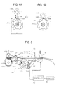
- FIG. 2 illustrates a configuration of the registration unit 105.
- the registration unit 105 includes a pair of feed rollers 150, a conveyance roller unit 151 including a gate-side roller 151A and a forwarding roller 151B (hereinafter also collectively “conveyance rollers 151A and 151B"), and a pair of timing rollers 152 arranged, in that order, in a sheet conveyance direction indicated by arrow A shown in FIG. 2 .
- the conveyance rollers 151A and 151B clamp the sheet therebetween and transport the sheet.
- Each of the pair of feed rollers 150 and the pair of timing rollers 152 is a pair of rollers of identical or similar diameter positioned facing each other across a sheet conveyance path.
- the conveyance rollers 151A and 151B serve as the first and second conveyance rollers, and the pair of timing rollers 152 serves as a pair of downstream rollers.
- a lower conveyance guide 153 and an upper conveyance guide 154 are provided along the sheet conveyance path between the feed rollers 150 and the conveyance rollers 151A and 151B.
- the lower conveyance guide 153 substantially parallels a tangential direction extending from the nip between the feed rollers 150.
- the upper conveyance guide 154 extends in the sheet conveyance direction and is positioned across the sheet conveyance path from the lower conveyance guide 153.
- the upper conveyance guide 154 is curved in such a manner that a part of the upper conveyance guide 154 protrudes in a direction away from the lower conveyance guide 153 (upward in FIG. 2 ).
- the protruding portion of the upper conveyance guide 154 is positioned at the same position as the position of a curved portion (like a partial loop or arch) of the sheet when the sheet is curved partly, which is described later.
- the conveyance roller unit 151 includes the gate-side roller 151A conveyance rollers 151A and 151B, namely, the gate-side roller 151A on the lower side and the forwarding roller 151B the upper side of the sheet conveyance path in FIG. 2 .
- the gate-side roller 151A is rotated by a unit 202 (shown in FIG. 5 ) that engage and disengage the pair of opposed conveyance rollers 151A and 151B from each other.
- the forwarding roller 151B on the upper side can be moved by the unit 202 toward and away from the gate-side roller 151A.
- reference characters 155 denotes a gate member
- 155A denotes a stopper of the gate member 155
- 155B denotes a guide surface of the gate member 155
- T denotes a distance from the nip between the timing rollers 152 to the stopper 155A of the gate member 155
- D denotes an external diameter of the gate-side roller 151A.
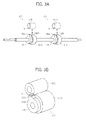
- FIGs. 3A and 3B illustrate the gate-side roller 151A in further detail.
- two pairs of the gate-side roller 151A and the forwarding roller 151B are provided, and two gate members 155 are provided coaxially with the respective gate-side rollers 151A.
- the gate member 155 is provided coaxially with the gate-side roller 151A, supported by a shaft of the gate-side roller 151A, and positioned adjacent to an edge surface of the gate-side roller 151A in the axial direction thereof.
- the gate member 155 includes the stopper 155A projecting into the sheet conveyance path beyond the circumference of the gate-side roller 151A so as to contact and stop the leading-end portion of the sheet.
- the stopper 155A extends in a limited portion of the gate member 155 in the circumferential direction.
- the guide surface 155B of the gate member 155 is continuous with the stopper 155A and has an external diameter identical or similar to that of the gate-side roller 151A.
- FIG. 4A illustrates an initial position of the gate member 155.
- the leading-end portion of the sheet contacts the stopper 155A and is stopped thereby. More specifically, at the initial position, a trailing-end portion of the stopper 155A in the sheet conveyance direction indicated by arrow A is positioned on a line connecting a center of rotation of the gate-side roller 151A and a center of rotation of the forwarding roller 151B positioned across the sheet conveyance path from the gate-side roller 151A. As the gate member 155 rotates in a direction indicated by arrow B shown in FIG. 4A , the trailing-end portion of the stopper 155A can move to a position away from the sheet conveyance path (hereinafter "non-contact position").
- the leading-end portion of the sheet can contact the stopper 155A at a position upstream from the nip between the gate-side roller 151A and the forwarding roller 151B in the sheet conveyance direction and can be stopped before entering the nip.
- the sheet that does not yet enter the nip is not clamped by the gate-side roller 151A and the forwarding roller 151B but can move, which is required to correct skew of the sheet, that is, inclination of the sheet relative to the sheet conveyance direction.
- the sheet When the leading-end portion of the sheet contacts the stopper 155A, the sheet deforms into a partial loop or arch. When the sheet is further forwarded with the leading-end portion stopped by the stopper 155A, the sheet rotates in such a direction that the curvature of the sheet is reduced by a moment centered about a leading edge of the sheet in contact with the stopper 155A. As a result, the leading-end portion of the sheet contacts the stopper 155A entirely, and thus the skew of the sheet can be corrected.
- the guide surface 155B has an external diameter identical or similar to an external diameter of the gate-side roller 151A.
- a wedgelike space can be defined by a circumferential surface of the forwarding roller 151B and the guide surface 155B positioned upstream from the nip between the gate-side roller 151A and the forwarding roller 151B in the sheet conveyance direction.
- the leading-end portion of the sheet can be reliably guided to the nip between the gate-side roller 151A and the forwarding roller 151B and thus reliably contacts the stopper 155A.
- the guide surface 155B be constructed of a low frictional surface to facilitate conveyance of the sheet even when the leading-end portion of the sheet slides on it.
- a notch N is formed in a portion of the forwarding roller 151B facing the gate-side roller 151A in a circumferential direction thereof as shown in FIG. 3A . That is, the notch N is positioned facing the stopper 155A of the gate member 155. With this shape, due to the ratio of the external diameter between them, after making several revolutions, the forwarding roller 151B can face the guide surface 155B without interference with the stopper 155A when the gate member 155 is at the initial position.
- the gate member 155 is designed not only to stop the leading-end portion of the sheet with the stopper 155A but also to increase the width of the portion of the sheet interposed between the forwarding roller 151B and the facing components (gate-side roller 151A and the gate member 155).
- Increasing the interposed width of the sheet can facilitate positional adjustment of the sheet in the sheet width direction (hereinafter also "shift adjustment"). More specifically, because the clamping force exerted on the sheet can be alleviated when the interposed area of the sheet is greater in the width direction, damage to the sheet can be reduced in the shift adjustment.
- the external diameter D of the gate-side roller 151A is determined to satisfy the following relation relative to the distance from the nip between the conveyance rollers 151A and 151B to the nip between the timing rollers 152.
- T ⁇ ⁇ D wherein T represents the distance between the nip between the timing rollers 152 and the stopper 155A of the gate member 155, and D represents the external diameter of the gate-side roller 151A.
- the leading-end portion of the sheet reaches the nip between the timing rollers 152 before the gate-side roller 151A completes one revolution, after which conveyance of the sheet is continued until the gate-side roller 151A completes the revolution, that is, for a duration corresponding to the difference between the circumferential length of the gate-side roller 151A and the distance T.
- the difference is provided so that the leading-end portion of the sheet can be transported to the nip between the timing rollers 152 reliably.
- the gate-side roller 151A is controlled to suspend the rotation simultaneous or substantially simultaneous with, or after the arrival of the stopper 155A of the gate member 155 at the initial position to stop the sheet (hereinafter also "contact position"). Then, the gate-side roller 151A resumes rotation when the sheet contacts the stopper 155A.
- a controller 200 shown in FIG. 5 sets the timing at which the gate-side roller 151A resumes rotation.
- a detector 201 detects the timing at which the feed rollers 150 start transporting the sheet.
- the controller 200 computes the amount by which the sheet is forwarded based on the amount by which the feed rollers 150 rotates from the start of sheet conveyance by the feed rollers 150, detected by the detector 201 and then sets when to resume the rotation of the gate-side roller 151A. This is based on the relation between the rotational amount of the feed rollers 150 and the distance from the feed rollers 150 to the stopper 155A of the gate member 155.
- one of the feed rollers 150 as well as one of the conveyance rollers 151A and 151B is movable toward and away from the opposed roller, that is, can approach and be away from the sheet conveyance path.
- the unit 202 shown in FIG. 5 , for engaging and disengaging the rollers from each other serves as the drive mechanism for this operation.
- the rollers are designed to move toward and withdraw from the sheet conveyance path so that the roller that currently has a capability of forwarding the sheet can be switched and that the position of the sheet can be adjusted (shift adjustment).
- the unit 202 includes a drive pulley M1 provided at an output shaft of a single motor M, a cam 156 for shifting the feed roller 150 (hereinafter also “feed roller shifting cam 156"), a pulley 156A provided at a support shaft of the feed roller shifting cam 156, a gear 157 on the side of the conveyance rollers 151A and 151B, a driven pulley 157A provided at the gear 157, and a belt 158 stretched around the pulley 156A and the driven pulley 157A.
- the controller 200 sets the timing at which the motor M rotates.
- the unit 202 further includes a pivotable lever 159 for moving the upper feed roller 150 toward and away from the sheet conveyance path, and a first end portion of the pivotable lever 159 is in contact with a cam surface (i.e., a circumferential surface) of the cam 156 for shifting the feed roller 150.
- the pivotable lever 159A is pivotable about a support point with a second end portion thereof in contact with the rotary shaft of one of the feed rollers 150 (in FIG. 5 , the lower feed roller 150).
- gears 151A1 and 151B1 are respectively supported by the shafts of the gate-side roller 151A and the forwarding roller 151B, coaxially therewith.
- the gear 157 provided on the side of the conveyance rollers 151A and 151B, engages the gears 151A1 and 151B1 and rotates the gears 151A1 and 151B1.
- the unit 202 for engaging and disengaging the rollers from each other further includes a cam 151C (hereinafter also “conveyance roller shifting cam 151C”) supported by the shaft of the gate-side roller 151A, coaxially therewith, for moving the forwarding roller 151B toward and away from the sheet conveyance path.
- a support portion of the forwarding roller 151B is in contact with a cam surface of the cam 151C.
- the cam 151C for shifting the conveyance roller 151B is in contact with a cam follower 159A provided at the first end portion of the pivotable lever 159 and can rotate in conjunction with rotation of the motor M.
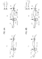
- FIGs. 6A through 7 illustrate operation to move the upper feed roller 150 and the forwarding roller 151B toward and away from the sheet conveyance path as well as rotational positions of the gate member 155.
- FIGs. 6A through 6D illustrate engagement states and disengagement states of the pair of feed rollers 150 and the pair of conveyance rollers 151A and 151B together with the rotational positions of the gate member 155.
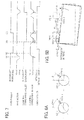
- FIG. 7 is a timing chart that illustrates timings at which the pair of feed rollers 150 and the pair of conveyance rollers 151A and 151B are engaged and disengaged from each other.
- FIG. 7 includes operational timings of a feed motor to drive the pair of feed rollers 150 and those of a clamping conveyance motor to drive the pair of conveyance rollers 151A and 151B.
- the controller 200 controls these motors.
- the gate member 155 which moves in conjunction with the gate-side roller 151A, is at the initial position to stop the leading-end portion of the sheet, the feed rollers 150 are in contact with each other (i.e., engagement state), and the conveyance rollers 151A and 151B are in contact with each other.
- the phase (rotational position) of the gate member 155 at that time is regarded as 0° for convenience.
- the cam surface of a small-diameter portion of the feed roller shifting cam 156 faces the pivotable lever 159
- the surface of a small-diameter portion ofthe conveyance roller shifting cam 151C faces the forwarding roller 151 B.
- the leading-end portion of the sheet transported by the feed rollers 150 is stopped by the stopper 155A ofthe gate member 155 provided at the conveyance roller 151A.
- the feed rollers 150 are further rotated with the leading-end portion of the sheet stopped by the stopper 155A, causing the sheet to curve like a partial loop. This state is shown in (a) and (b) in FIG. 6A , and corresponds to a timing (A) shown in FIG. 7 .
- the gate member 155 While rotating unidirectionally with the gate-side roller 151A consecutively, the gate member 155 stops temporarily when or about when the stopper 155A arrives at the contact position, or the gate member 155 stops after the stopper 155A arrives at the contact position. Rotation of the gate member 155 is resumed with a signal transmitted by the controller 200.
- the gate member 155 has passed the initial position where the portion to stop the sheet (i.e., the stopper 155A) enters the sheet conveyance path, the sheet is transported toward the nip between the timing rollers 152 by the gate-side roller 151A and the forwarding roller 151B in addition to the resilience of the sheet for restoring its original shape.
- the cam 156 for shifting the feed roller 150 rotates to a position where a large-diameter portion of the cam 156 faces the pivotable lever 159, and accordingly the feed roller 150 is moved away from the sheet conveyance path to a non-contact position.
- This state is shown in FIG. 6B , and corresponds to a timing (B) shown in FIG. 7 .
- timing rollers 152 clamping the leading-end portion of the sheet state rotating timed to coincide with the image position, the sheet is transported to the secondary-transfer position.
- the feed rollers 150 return to the engagement state to transport a subsequent sheet. This state is shown in FIG. 6D , and corresponds to a timing (D) shown in FIG. 7 .
- the rotational amount of the motor M is set so that the stopper 155A is moved from the non-contact position to the contact position after a trailing-end portion ofthe sheet passes between the pair of conveyance rollers 151A and 151B.
- the sheet can be stopped and released simply by rotating the gate member 155 consecutively in the unidirectional direction in conjunction with one of the conveyance rollers 151A and 151B.
- This configuration does not require reverse movement of the gate member 155 in transition between stop of the sheet and release of the sheet. Therefore, waiting time can be reduced and conveyance of the subsequent sheet can be started within a reduced time.
- the stopper 155A does not interfere with the sheet clamped by the pair of conveyance rollers 151A and 151B. Therefore, the sheet can be prevented from getting caught in the nip between the stopper 155A and the conveyance rollers 151A and 151B, and thus deformation of the sheet can be prevented.
- the interference between the stopper 155A and the sheet may be prevented by stopping the pair of conveyance rollers 151A and 151B before the stopper 155A is moved from the non-contact position to the contact position.
- the leading-end portion of the sheet to be stopped by the gate member 155 can be reliably guided to the stopper 155A by the guide surface 155B of the gate member 155 provided adjacent to the stopper 155A of the gate member 155.
- the guide surface 155B of the gate member 155 is also used to transport the sheet clamped between them together with the forwarding roller 151B facing it. Consequently, the pressure to the sheet is not focused but can be dispersed, inhibiting the sheet from skewing or inclining relative to the sheet conveyance direction.
- deformation of or damage to the sheet caused by the contact with the stopper 155A may be prevented by keeping the conveyance rollers 151A and 151B rotating although the conveyance rollers 151A and 151B are disengaged from each other before the stopper 155A is moved from the non-contact position to the contact position.
- the sheet is not clamped between the conveyance rollers 151A and 151B, the sheet is not caught between the stopper 155A and the nip between the conveyance rollers 151A and 151B, and thus deformation of the sheet can be prevented.
- FIGs. 8A and 8B illustrate a configuration in which multiple gate members 155 are arranged in the axial direction of the gate-side roller 151A, and stoppers 155A of the respective gate members 155 can be set at different positions in the circumferential direction of the gate-side roller 151A.
- the skew of the sheet is corrected as follows.
- a detector detects passage of a reference edge and the opposite edge of the reference edge in the direction perpendicular to the sheet conveyance direction, and the amount of deviation of the sheet between the reference edge and the opposite edge is calculated. Then, the circumferential position of the stopper 155A of the gate member 155 at the opposite edge is shifted from that of the gate member 155 on a reference side in the axial direction.
- FIGs. 8A and 8B are schematic diagrams illustrating differences in circumferential phase between stoppers 155A-1 and 155A-2 (hereinafter also collectively “stoppers 155A”) of two gate members 155-1 and 155-2 (hereinafter also collectively “gate members 155").
- FIG. 8A illustrates circumferential phases (rotational positions) of the stoppers 155A-1 and 155A-2 of the gate members 155-1 and 155-2 as viewed from an axial end side of the gate-side roller 151A shown in FIG. 5 .
- the gate member 155-1 is positioned on the reference side, whereas the gate member 155-2 is on the opposite side in FIGs. 8A and 8B .
- the stopper 155A-1 of the gate member 155-1 on the reference side (on left in FIGs. 8A and 8B ) is positioned at an angle of ⁇ + ⁇
- the stopper 155A-2 of the gate member 155-2 on the opposite side is at an angle of ⁇ .
- the leading-end portion of the sheet comes into contact with the stopper 155A-1 on the reference side before contacting the stopper 155A-2 on the opposite side.
- the feed rollers 150 shown in FIG. 2
- the leading-end portion of the sheet on the opposite side rotates about the leading-end portion on the reference side stopped by the stopper 155A-1. Accordingly, the skew of the sheet indicated by solid lines in FIG. 8B is corrected as indicated by broken lines in FIG. 8B .
- stoppers 155A-1 and 155A-2 rotate an identical or similar amount (i.e., angle)
- the position of the sheet on the opposite side is adjusted by an amount corresponding to the difference in circumferential phase.
- the sheet is substantially aligned with the axial direction perpendicular to the sheet conveyance direction as indicated by broken lines in FIG. 8B .
- the above-described difference in circumferential phase is not so large because the amount of skew of the sheet is typically limited.
- the difference in circumferential phase may be such an amount that, when sheet conveyance is stopped on one side in the sheet width direction, the opposite side of the sheet can be rotated about the portion stopped by the stopper 155A by a force for forwarding the sheet, thus correcting the skew of the sheet.
- shift adjustment means shifting the sheet in the sheet width direction to align a center position of the sheet with a center position of the image in the direction perpendicular to the sheet conveyance direction.
- the conveyance rollers 151A and 151B are supported by a common housing as the conveyance roller unit 151, the position of the conveyance roller unit 151 in the axial direction is adjusted, and engagement between the feed rollers 150 as well as that between the conveyance rollers 151A and 151B is adjusted.
- the mechanism for shift adjustment includes a sheet detector CIS to detect the position of the sheet in the sheet width direction, provided in an axial end portion of the shaft of the conveyance rollers 151A and 151B, a cam 14 to move the conveyance roller unit 151 in the axial direction based on detection results by the detector CIS, and a motor 160 to drive the cam 14 (hereinafter "shift motor 160").
- the conveyance roller unit 151 is pressed against the cam 14 constantly. As the cam 14 rotates, the conveyance roller unit 151 is moved in the axial direction indicated by arrow 15 shown in FIG. 11 perpendicular to the sheet conveyance direction.
- reference number 13 represents a spring
- reference character S represent the sheet.
- the cam 14 driven by the shift motor 160 is designed to have a cam profile to move the conveyance roller unit 151 in the axial direction.
- the cam 14 moves the conveyance roller unit 151 in the axial direction by the amount corresponding to the rotational phase of the shift motor 160, aligning the center position of the sheet with the center position of the image in the sheet width direction.
- Such a configuration is disclosed in US Patent No. 7722039 , which is incorporated by reference herein.
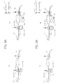
- FIGs. 9A through 9D illustrate engagement states and disengagement states between the feed rollers 150 and that between the conveyance rollers 151A and 151B together with the rotational position of the gate member 155 regarding the shift adjustment.
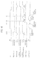
- FIG. 10 is a timing chart that illustrates timings at which the feed rollers 150 and the conveyance rollers 151A and 151B are engaged and disengaged from each other. It is to be noted that the states shown in FIGs. 9A, 9B , 9C , and 9D are similar to those shown in FIGs. 6A through 6D and are described only briefly below.
- FIGs. 9A through 10 The configuration shown in FIGs. 9A through 10 is different in that shift adjustment operation is added from that shown in FIGs. 6A through 7 . More specifically, as shown in FIG. 9C' and (C1) in FIG. 10 , the conveyance rollers 151A and 151B are kept in contact with each other until the gate member 155 rotates to an angle of about 260° unidirectionally similarly to the period during which the gate member 155 rotates from the initial position to an angle of about 30° unidirectionally as shown in FIG. 9B . At that time, the feed rollers 150 are disengaged from each other.
- the position of the conveyance roller unit 151 in the axial direction is set with the cam 14 that moves from the initial position shown in FIG. 9A , driven by the shift motor 160.
- the sheet clamped between the pair of conveyance rollers 151A and 151 B is forwarded to the timing rollers 152 with the center position of the sheet aligned with the center position of the image or a predetermined reference position in the sheet width direction.
- the sheet aligned in the sheet width direction and transported by the pair of conveyance rollers 151A and 151B is caught in the nip between the timing rollers 152 as shown in FIG. 9C and (C2) in FIG. 10 . Then, the timing rollers 152 forward the sheet, timed to coincide with the position of the image. When the timing rollers 152 transport the leading-end portion of the sheet caught in the nip therebetween, one of the conveyance rollers 151A and 151B is away from the sheet conveyance path similarly to the state shown in FIG. 6C .
- timing rollers 152 clamping the leading-end portion of the sheet state rotating timed to coincide with the image position, the sheet is transported to the secondary-transfer position.
- the feed rollers 150 return to the engagement state to transport a subsequent sheet. This state is shown in FIG. 9D , and corresponds to a timing (D) shown in FIG. 10 .
- the gate member 155 to stop the leading-end portion of the sheet is provided coaxially with one of the conveyance rollers 151A and 151B and configured to rotate unidirectionally and consecutively in conjunction with rotation of the conveyance roller 151A. It is not necessary to switch the rotational direction of the gate member 155. Consequently, loss of time caused by the switch of the rotational direction of the gate member 155 can be eliminated.
- the shift adjustment can be performed in the duration of time corresponding to the difference in distance. That is, the position of the sheet in the direction perpendicular to the sheet conveyance direction can be adjusted.
- the sheet that is curved into a partial loop is guided by the guide surface 155B of the gate member 155 to the nip between the conveyance rollers 151A and 151B.
- the gate member 155 has multiple capabilities.
- the conveyance rollers 151A and 151B are stopped or disengaged from each other to prevent the stopper 155A from contacting the sheet clamped between the conveyance rollers 151A and 151B. Accordingly, deformation of and damage to the sheet can be prevented or reduced.
Landscapes
- Engineering & Computer Science (AREA)
- Mechanical Engineering (AREA)
- Registering Or Overturning Sheets (AREA)
- Paper Feeding For Electrophotography (AREA)
- Replacement Of Web Rolls (AREA)
Applications Claiming Priority (2)
| Application Number | Priority Date | Filing Date | Title |
|---|---|---|---|
| JP2010146323 | 2010-06-28 | ||
| JP2011078172A JP5696565B2 (ja) | 2010-06-28 | 2011-03-31 | シート搬送装置および画像形成装置 |
Publications (3)
| Publication Number | Publication Date |
|---|---|
| EP2399852A2 true EP2399852A2 (de) | 2011-12-28 |
| EP2399852A3 EP2399852A3 (de) | 2014-08-20 |
| EP2399852B1 EP2399852B1 (de) | 2016-03-30 |
Family
ID=44721137
Family Applications (1)
| Application Number | Title | Priority Date | Filing Date |
|---|---|---|---|
| EP11169598.7A Active EP2399852B1 (de) | 2010-06-28 | 2011-06-10 | Blattfördereinheit |
Country Status (3)
| Country | Link |
|---|---|
| US (1) | US8317192B2 (de) |
| EP (1) | EP2399852B1 (de) |
| JP (1) | JP5696565B2 (de) |
Cited By (2)
| Publication number | Priority date | Publication date | Assignee | Title |
|---|---|---|---|---|
| WO2013118789A1 (en) * | 2012-02-08 | 2013-08-15 | Canon Kabushiki Kaisha | Sheet conveying apparatus and image forming apparatus |
| EP2845824A1 (de) * | 2013-09-09 | 2015-03-11 | Ricoh Company Ltd. | Blattfördervorrichtung und Bilderzeugungsvorrichtung damit |
Families Citing this family (16)
| Publication number | Priority date | Publication date | Assignee | Title |
|---|---|---|---|---|
| DE602007009614D1 (de) * | 2006-08-22 | 2010-11-18 | Ricoh Kk | Blattausrichtungsvorrichtung und Bilderzeugungsvorrichtung damit |
| JP5950658B2 (ja) * | 2011-04-22 | 2016-07-13 | キヤノン株式会社 | シート搬送装置及び画像形成装置 |
| JP5936173B2 (ja) | 2011-12-28 | 2016-06-15 | 株式会社リコー | シート材位置補正装置、及び、画像形成装置 |
| JP2013193815A (ja) * | 2012-03-16 | 2013-09-30 | Ricoh Co Ltd | シート搬送装置および画像形成装置 |
| US8905401B2 (en) * | 2012-05-31 | 2014-12-09 | Ricoh Company, Ltd. | Printing medium conveying device and image forming apparatus |
| JP5997529B2 (ja) * | 2012-07-24 | 2016-09-28 | 理想科学工業株式会社 | 給紙装置 |
| JP5998759B2 (ja) * | 2012-08-31 | 2016-09-28 | 株式会社リコー | シート搬送装置および画像形成装置 |
| JP6049182B2 (ja) * | 2012-11-16 | 2016-12-21 | ホリゾン・インターナショナル株式会社 | 用紙搬送機構 |
| JP6049445B2 (ja) * | 2012-12-26 | 2016-12-21 | キヤノン株式会社 | シート搬送装置及び画像形成装置 |
| JP2015020902A (ja) * | 2013-07-23 | 2015-02-02 | キヤノン株式会社 | 斜行補正装置及び画像形成装置 |
| JP2016137987A (ja) * | 2015-01-29 | 2016-08-04 | 株式会社リコー | 搬送装置、及び、画像形成装置 |
| JP6485339B2 (ja) * | 2015-12-08 | 2019-03-20 | コニカミノルタ株式会社 | 画像形成装置 |
| JP2016117590A (ja) * | 2016-03-29 | 2016-06-30 | 富士ゼロックス株式会社 | シート搬送装置 |
| JP2016117591A (ja) * | 2016-03-29 | 2016-06-30 | 富士ゼロックス株式会社 | シート搬送装置 |
| EP3348504B1 (de) | 2017-01-11 | 2021-02-03 | Ricoh Company, Ltd. | Blattfördervorrichtung und bilderzeugungsvorrichtung mit der blattfördervorrichtung |
| JP2023146012A (ja) * | 2022-03-29 | 2023-10-12 | 富士フイルムビジネスイノベーション株式会社 | シート搬送装置及び画像形成装置 |
Citations (5)
| Publication number | Priority date | Publication date | Assignee | Title |
|---|---|---|---|---|
| JPS64555U (de) | 1987-06-23 | 1989-01-05 | ||
| JPH05338865A (ja) | 1992-06-11 | 1993-12-21 | Fuji Xerox Co Ltd | 画像形成装置の用紙整合装置 |
| US7722039B2 (en) | 2007-05-31 | 2010-05-25 | Ricoh Company, Limited | Sheet conveying device and image forming apparatus |
| JP2010146323A (ja) | 2008-12-19 | 2010-07-01 | Fujitsu Ltd | データ選択支援プログラム、データ選択支援装置およびデータ選択支援方法 |
| JP2011078172A (ja) | 2009-09-29 | 2011-04-14 | Hitachi Koki Co Ltd | 充電装置 |
Family Cites Families (18)
| Publication number | Priority date | Publication date | Assignee | Title |
|---|---|---|---|---|
| JPS599227Y2 (ja) * | 1978-08-22 | 1984-03-23 | 株式会社リコー | シ−ト給送装置 |
| JPS5878938A (ja) * | 1981-11-05 | 1983-05-12 | Toshiba Corp | 帳票アライメント装置 |
| JPS60101558A (ja) | 1983-11-08 | 1985-06-05 | Fuji Xerox Co Ltd | 複写機の用紙搬送装置 |
| JPS6127853A (ja) * | 1984-07-13 | 1986-02-07 | Fuji Xerox Co Ltd | 給紙装置 |
| JP2535569B2 (ja) | 1986-11-25 | 1996-09-18 | コニカ株式会社 | 新規な写真用シアンカプラ―を含有するハロゲン化銀カラ―写真感光材料 |
| JPH03259860A (ja) * | 1990-03-07 | 1991-11-19 | Kishi Seisakusho:Kk | 毎葉整列装置 |
| JPH0692518A (ja) | 1992-09-11 | 1994-04-05 | Fuji Xerox Co Ltd | 画像形成装置の用紙整合装置 |
| JPH07172637A (ja) | 1993-12-20 | 1995-07-11 | Canon Inc | 用紙搬送装置 |
| JP3768578B2 (ja) * | 1996-01-08 | 2006-04-19 | キヤノン株式会社 | シート斜行補正装置及びシート搬送装置及び画像形成装置 |
| JPH10181954A (ja) * | 1996-12-27 | 1998-07-07 | Canon Inc | シート材斜行矯正装置及び画像形成装置 |
| JP3981485B2 (ja) | 1998-12-18 | 2007-09-26 | 株式会社リコー | シート搬送装置 |
| JP2002019990A (ja) * | 2000-07-06 | 2002-01-23 | Canon Inc | シート搬送装置及びこれを備えた画像形成装置 |
| KR100461590B1 (ko) * | 2002-08-12 | 2004-12-14 | 삼성전자주식회사 | 화상형성기기의 용지이송장치 |
| JP4715578B2 (ja) | 2005-06-17 | 2011-07-06 | コニカミノルタビジネステクノロジーズ株式会社 | 画像形成装置 |
| KR101244680B1 (ko) * | 2006-06-20 | 2013-03-18 | 삼성전자주식회사 | 멀티 패싱장치 및 이를 포함하는 화상형성장치 |
| JP4750748B2 (ja) * | 2006-06-21 | 2011-08-17 | 株式会社リコー | 用紙搬送装置、これを用いた画像形成装置 |
| US8213851B2 (en) * | 2007-03-23 | 2012-07-03 | Ricoh Company, Limited | Conveying device and image forming apparatus |
| CN101412478B (zh) * | 2007-10-19 | 2011-05-18 | 旭丽电子(广州)有限公司 | 介质偏斜纠正机构 |
-
2011
- 2011-03-31 JP JP2011078172A patent/JP5696565B2/ja active Active
- 2011-06-01 US US13/067,437 patent/US8317192B2/en active Active
- 2011-06-10 EP EP11169598.7A patent/EP2399852B1/de active Active
Patent Citations (5)
| Publication number | Priority date | Publication date | Assignee | Title |
|---|---|---|---|---|
| JPS64555U (de) | 1987-06-23 | 1989-01-05 | ||
| JPH05338865A (ja) | 1992-06-11 | 1993-12-21 | Fuji Xerox Co Ltd | 画像形成装置の用紙整合装置 |
| US7722039B2 (en) | 2007-05-31 | 2010-05-25 | Ricoh Company, Limited | Sheet conveying device and image forming apparatus |
| JP2010146323A (ja) | 2008-12-19 | 2010-07-01 | Fujitsu Ltd | データ選択支援プログラム、データ選択支援装置およびデータ選択支援方法 |
| JP2011078172A (ja) | 2009-09-29 | 2011-04-14 | Hitachi Koki Co Ltd | 充電装置 |
Cited By (7)
| Publication number | Priority date | Publication date | Assignee | Title |
|---|---|---|---|---|
| WO2013118789A1 (en) * | 2012-02-08 | 2013-08-15 | Canon Kabushiki Kaisha | Sheet conveying apparatus and image forming apparatus |
| US9388005B2 (en) | 2012-02-08 | 2016-07-12 | Canon Kabushiki Kaisha | Sheet conveying apparatus and image forming apparatus |
| US9586778B2 (en) | 2012-02-08 | 2017-03-07 | Canon Kabushiki Kaisha | Sheet conveying apparatus and image forming apparatus |
| US9938102B2 (en) | 2012-02-08 | 2018-04-10 | Canon Kabushiki Kaisha | Sheet conveying apparatus and image forming apparatus |
| US10759618B2 (en) | 2012-02-08 | 2020-09-01 | Canon Kabushiki Kaisha | Sheet conveying apparatus and image forming apparatus |
| EP2845824A1 (de) * | 2013-09-09 | 2015-03-11 | Ricoh Company Ltd. | Blattfördervorrichtung und Bilderzeugungsvorrichtung damit |
| US9174817B2 (en) | 2013-09-09 | 2015-11-03 | Ricoh Company, Ltd. | Sheet conveying device and image forming apparatus incorporating same |
Also Published As
| Publication number | Publication date |
|---|---|
| JP2012030971A (ja) | 2012-02-16 |
| US8317192B2 (en) | 2012-11-27 |
| EP2399852B1 (de) | 2016-03-30 |
| EP2399852A3 (de) | 2014-08-20 |
| US20110316226A1 (en) | 2011-12-29 |
| JP5696565B2 (ja) | 2015-04-08 |
Similar Documents
| Publication | Publication Date | Title |
|---|---|---|
| EP2399852B1 (de) | Blattfördereinheit | |
| JP4750754B2 (ja) | シート搬送装置および画像形成装置 | |
| JP6202373B2 (ja) | 搬送装置、及び、画像形成装置 | |
| US9026029B2 (en) | Sheet conveyance apparatus and image forming apparatus | |
| EP1892582B1 (de) | Blattausrichtungsvorrichtung und Bilderzeugungsvorrichtung damit | |
| EP1980512A2 (de) | Blattausrichtungsvorrichtung und Bilderzeugungsvorrichtung, die diese verwendet | |
| US7810811B2 (en) | Sheet conveying apparatus and image forming apparatus | |
| US8684353B2 (en) | Sheet conveying apparatus and image forming apparatus | |
| EP2845824B1 (de) | Blattfördervorrichtung und Bilderzeugungsvorrichtung damit | |
| US8678382B2 (en) | Sheet conveyance apparatus and image forming apparatus | |
| US20130026706A1 (en) | Image forming apparatus | |
| US9272862B2 (en) | Sheet feeding device and image forming apparatus | |
| WO2013084474A1 (en) | Sheet conveying apparatus and image forming apparatus | |
| US9206005B2 (en) | Sheet conveying apparatus and image forming apparatus | |
| US9139391B2 (en) | Sheet conveyor, image forming apparatus incorporating same, and method of preventing sheet skew | |
| US20150115525A1 (en) | Sheet conveyance apparatus and image forming apparatus | |
| JP6225434B2 (ja) | 画像形成装置 | |
| JP6366245B2 (ja) | シート搬送装置及び画像形成装置 | |
| US8181956B2 (en) | Sheet transport device for image forming apparatus | |
| JP5998759B2 (ja) | シート搬送装置および画像形成装置 | |
| US12577071B2 (en) | Sheet conveyance apparatus and image forming apparatus | |
| JP2001253595A (ja) | 用紙搬送装置 | |
| JP5773589B2 (ja) | シート搬送装置及び画像形成装置 | |
| JP6552252B2 (ja) | 画像形成装置 | |
| US20190082068A1 (en) | Paper conveying device and image forming apparatus |
Legal Events
| Date | Code | Title | Description |
|---|---|---|---|
| 17P | Request for examination filed |
Effective date: 20110610 |
|
| AK | Designated contracting states |
Kind code of ref document: A2 Designated state(s): AL AT BE BG CH CY CZ DE DK EE ES FI FR GB GR HR HU IE IS IT LI LT LU LV MC MK MT NL NO PL PT RO RS SE SI SK SM TR |
|
| AX | Request for extension of the european patent |
Extension state: BA ME |
|
| PUAI | Public reference made under article 153(3) epc to a published international application that has entered the european phase |
Free format text: ORIGINAL CODE: 0009012 |
|
| PUAL | Search report despatched |
Free format text: ORIGINAL CODE: 0009013 |
|
| AK | Designated contracting states |
Kind code of ref document: A3 Designated state(s): AL AT BE BG CH CY CZ DE DK EE ES FI FR GB GR HR HU IE IS IT LI LT LU LV MC MK MT NL NO PL PT RO RS SE SI SK SM TR |
|
| AX | Request for extension of the european patent |
Extension state: BA ME |
|
| RIC1 | Information provided on ipc code assigned before grant |
Ipc: B65H 9/00 20060101ALI20140714BHEP Ipc: B65H 5/06 20060101ALI20140714BHEP Ipc: B65H 9/06 20060101AFI20140714BHEP Ipc: B65H 7/02 20060101ALI20140714BHEP |
|
| RIC1 | Information provided on ipc code assigned before grant |
Ipc: B65H 5/06 20060101ALI20150819BHEP Ipc: B65H 9/06 20060101AFI20150819BHEP Ipc: B65H 7/02 20060101ALI20150819BHEP |
|
| GRAP | Despatch of communication of intention to grant a patent |
Free format text: ORIGINAL CODE: EPIDOSNIGR1 |
|
| INTG | Intention to grant announced |
Effective date: 20150930 |
|
| GRAS | Grant fee paid |
Free format text: ORIGINAL CODE: EPIDOSNIGR3 |
|
| GRAA | (expected) grant |
Free format text: ORIGINAL CODE: 0009210 |
|
| AK | Designated contracting states |
Kind code of ref document: B1 Designated state(s): AL AT BE BG CH CY CZ DE DK EE ES FI FR GB GR HR HU IE IS IT LI LT LU LV MC MK MT NL NO PL PT RO RS SE SI SK SM TR |
|
| REG | Reference to a national code |
Ref country code: GB Ref legal event code: FG4D |
|
| REG | Reference to a national code |
Ref country code: CH Ref legal event code: EP |
|
| REG | Reference to a national code |
Ref country code: AT Ref legal event code: REF Ref document number: 785131 Country of ref document: AT Kind code of ref document: T Effective date: 20160415 |
|
| REG | Reference to a national code |
Ref country code: IE Ref legal event code: FG4D |
|
| REG | Reference to a national code |
Ref country code: DE Ref legal event code: R096 Ref document number: 602011024522 Country of ref document: DE |
|
| REG | Reference to a national code |
Ref country code: FR Ref legal event code: PLFP Year of fee payment: 6 |
|
| REG | Reference to a national code |
Ref country code: LT Ref legal event code: MG4D |
|
| PG25 | Lapsed in a contracting state [announced via postgrant information from national office to epo] |
Ref country code: FI Free format text: LAPSE BECAUSE OF FAILURE TO SUBMIT A TRANSLATION OF THE DESCRIPTION OR TO PAY THE FEE WITHIN THE PRESCRIBED TIME-LIMIT Effective date: 20160330 Ref country code: HR Free format text: LAPSE BECAUSE OF FAILURE TO SUBMIT A TRANSLATION OF THE DESCRIPTION OR TO PAY THE FEE WITHIN THE PRESCRIBED TIME-LIMIT Effective date: 20160330 Ref country code: GR Free format text: LAPSE BECAUSE OF FAILURE TO SUBMIT A TRANSLATION OF THE DESCRIPTION OR TO PAY THE FEE WITHIN THE PRESCRIBED TIME-LIMIT Effective date: 20160701 Ref country code: NO Free format text: LAPSE BECAUSE OF FAILURE TO SUBMIT A TRANSLATION OF THE DESCRIPTION OR TO PAY THE FEE WITHIN THE PRESCRIBED TIME-LIMIT Effective date: 20160630 |
|
| REG | Reference to a national code |
Ref country code: NL Ref legal event code: MP Effective date: 20160330 |
|
| REG | Reference to a national code |
Ref country code: AT Ref legal event code: MK05 Ref document number: 785131 Country of ref document: AT Kind code of ref document: T Effective date: 20160330 |
|
| PG25 | Lapsed in a contracting state [announced via postgrant information from national office to epo] |
Ref country code: LT Free format text: LAPSE BECAUSE OF FAILURE TO SUBMIT A TRANSLATION OF THE DESCRIPTION OR TO PAY THE FEE WITHIN THE PRESCRIBED TIME-LIMIT Effective date: 20160330 Ref country code: LV Free format text: LAPSE BECAUSE OF FAILURE TO SUBMIT A TRANSLATION OF THE DESCRIPTION OR TO PAY THE FEE WITHIN THE PRESCRIBED TIME-LIMIT Effective date: 20160330 Ref country code: SE Free format text: LAPSE BECAUSE OF FAILURE TO SUBMIT A TRANSLATION OF THE DESCRIPTION OR TO PAY THE FEE WITHIN THE PRESCRIBED TIME-LIMIT Effective date: 20160330 Ref country code: RS Free format text: LAPSE BECAUSE OF FAILURE TO SUBMIT A TRANSLATION OF THE DESCRIPTION OR TO PAY THE FEE WITHIN THE PRESCRIBED TIME-LIMIT Effective date: 20160330 |
|
| PG25 | Lapsed in a contracting state [announced via postgrant information from national office to epo] |
Ref country code: NL Free format text: LAPSE BECAUSE OF FAILURE TO SUBMIT A TRANSLATION OF THE DESCRIPTION OR TO PAY THE FEE WITHIN THE PRESCRIBED TIME-LIMIT Effective date: 20160330 |
|
| PG25 | Lapsed in a contracting state [announced via postgrant information from national office to epo] |
Ref country code: PL Free format text: LAPSE BECAUSE OF FAILURE TO SUBMIT A TRANSLATION OF THE DESCRIPTION OR TO PAY THE FEE WITHIN THE PRESCRIBED TIME-LIMIT Effective date: 20160330 Ref country code: EE Free format text: LAPSE BECAUSE OF FAILURE TO SUBMIT A TRANSLATION OF THE DESCRIPTION OR TO PAY THE FEE WITHIN THE PRESCRIBED TIME-LIMIT Effective date: 20160330 Ref country code: IS Free format text: LAPSE BECAUSE OF FAILURE TO SUBMIT A TRANSLATION OF THE DESCRIPTION OR TO PAY THE FEE WITHIN THE PRESCRIBED TIME-LIMIT Effective date: 20160730 |
|
| PG25 | Lapsed in a contracting state [announced via postgrant information from national office to epo] |
Ref country code: AT Free format text: LAPSE BECAUSE OF FAILURE TO SUBMIT A TRANSLATION OF THE DESCRIPTION OR TO PAY THE FEE WITHIN THE PRESCRIBED TIME-LIMIT Effective date: 20160330 Ref country code: CZ Free format text: LAPSE BECAUSE OF FAILURE TO SUBMIT A TRANSLATION OF THE DESCRIPTION OR TO PAY THE FEE WITHIN THE PRESCRIBED TIME-LIMIT Effective date: 20160330 Ref country code: RO Free format text: LAPSE BECAUSE OF FAILURE TO SUBMIT A TRANSLATION OF THE DESCRIPTION OR TO PAY THE FEE WITHIN THE PRESCRIBED TIME-LIMIT Effective date: 20160330 Ref country code: PT Free format text: LAPSE BECAUSE OF FAILURE TO SUBMIT A TRANSLATION OF THE DESCRIPTION OR TO PAY THE FEE WITHIN THE PRESCRIBED TIME-LIMIT Effective date: 20160801 Ref country code: SM Free format text: LAPSE BECAUSE OF FAILURE TO SUBMIT A TRANSLATION OF THE DESCRIPTION OR TO PAY THE FEE WITHIN THE PRESCRIBED TIME-LIMIT Effective date: 20160330 Ref country code: ES Free format text: LAPSE BECAUSE OF FAILURE TO SUBMIT A TRANSLATION OF THE DESCRIPTION OR TO PAY THE FEE WITHIN THE PRESCRIBED TIME-LIMIT Effective date: 20160330 Ref country code: SK Free format text: LAPSE BECAUSE OF FAILURE TO SUBMIT A TRANSLATION OF THE DESCRIPTION OR TO PAY THE FEE WITHIN THE PRESCRIBED TIME-LIMIT Effective date: 20160330 |
|
| PG25 | Lapsed in a contracting state [announced via postgrant information from national office to epo] |
Ref country code: BE Free format text: LAPSE BECAUSE OF FAILURE TO SUBMIT A TRANSLATION OF THE DESCRIPTION OR TO PAY THE FEE WITHIN THE PRESCRIBED TIME-LIMIT Effective date: 20160330 Ref country code: IT Free format text: LAPSE BECAUSE OF FAILURE TO SUBMIT A TRANSLATION OF THE DESCRIPTION OR TO PAY THE FEE WITHIN THE PRESCRIBED TIME-LIMIT Effective date: 20160330 |
|
| REG | Reference to a national code |
Ref country code: DE Ref legal event code: R097 Ref document number: 602011024522 Country of ref document: DE |
|
| PG25 | Lapsed in a contracting state [announced via postgrant information from national office to epo] |
Ref country code: MC Free format text: LAPSE BECAUSE OF FAILURE TO SUBMIT A TRANSLATION OF THE DESCRIPTION OR TO PAY THE FEE WITHIN THE PRESCRIBED TIME-LIMIT Effective date: 20160330 Ref country code: DK Free format text: LAPSE BECAUSE OF FAILURE TO SUBMIT A TRANSLATION OF THE DESCRIPTION OR TO PAY THE FEE WITHIN THE PRESCRIBED TIME-LIMIT Effective date: 20160330 |
|
| REG | Reference to a national code |
Ref country code: CH Ref legal event code: PL |
|
| PLBE | No opposition filed within time limit |
Free format text: ORIGINAL CODE: 0009261 |
|
| STAA | Information on the status of an ep patent application or granted ep patent |
Free format text: STATUS: NO OPPOSITION FILED WITHIN TIME LIMIT |
|
| 26N | No opposition filed |
Effective date: 20170103 |
|
| REG | Reference to a national code |
Ref country code: IE Ref legal event code: MM4A |
|
| PG25 | Lapsed in a contracting state [announced via postgrant information from national office to epo] |
Ref country code: LI Free format text: LAPSE BECAUSE OF NON-PAYMENT OF DUE FEES Effective date: 20160630 Ref country code: CH Free format text: LAPSE BECAUSE OF NON-PAYMENT OF DUE FEES Effective date: 20160630 |
|
| PG25 | Lapsed in a contracting state [announced via postgrant information from national office to epo] |
Ref country code: IE Free format text: LAPSE BECAUSE OF NON-PAYMENT OF DUE FEES Effective date: 20160610 Ref country code: SI Free format text: LAPSE BECAUSE OF FAILURE TO SUBMIT A TRANSLATION OF THE DESCRIPTION OR TO PAY THE FEE WITHIN THE PRESCRIBED TIME-LIMIT Effective date: 20160330 |
|
| REG | Reference to a national code |
Ref country code: FR Ref legal event code: PLFP Year of fee payment: 7 |
|
| PG25 | Lapsed in a contracting state [announced via postgrant information from national office to epo] |
Ref country code: HU Free format text: LAPSE BECAUSE OF FAILURE TO SUBMIT A TRANSLATION OF THE DESCRIPTION OR TO PAY THE FEE WITHIN THE PRESCRIBED TIME-LIMIT; INVALID AB INITIO Effective date: 20110610 Ref country code: CY Free format text: LAPSE BECAUSE OF FAILURE TO SUBMIT A TRANSLATION OF THE DESCRIPTION OR TO PAY THE FEE WITHIN THE PRESCRIBED TIME-LIMIT Effective date: 20160330 |
|
| REG | Reference to a national code |
Ref country code: FR Ref legal event code: PLFP Year of fee payment: 8 |
|
| PG25 | Lapsed in a contracting state [announced via postgrant information from national office to epo] |
Ref country code: TR Free format text: LAPSE BECAUSE OF FAILURE TO SUBMIT A TRANSLATION OF THE DESCRIPTION OR TO PAY THE FEE WITHIN THE PRESCRIBED TIME-LIMIT Effective date: 20160330 Ref country code: MT Free format text: LAPSE BECAUSE OF NON-PAYMENT OF DUE FEES Effective date: 20160630 Ref country code: LU Free format text: LAPSE BECAUSE OF NON-PAYMENT OF DUE FEES Effective date: 20160610 Ref country code: MK Free format text: LAPSE BECAUSE OF FAILURE TO SUBMIT A TRANSLATION OF THE DESCRIPTION OR TO PAY THE FEE WITHIN THE PRESCRIBED TIME-LIMIT Effective date: 20160330 |
|
| PG25 | Lapsed in a contracting state [announced via postgrant information from national office to epo] |
Ref country code: BG Free format text: LAPSE BECAUSE OF FAILURE TO SUBMIT A TRANSLATION OF THE DESCRIPTION OR TO PAY THE FEE WITHIN THE PRESCRIBED TIME-LIMIT Effective date: 20160330 |
|
| PG25 | Lapsed in a contracting state [announced via postgrant information from national office to epo] |
Ref country code: AL Free format text: LAPSE BECAUSE OF FAILURE TO SUBMIT A TRANSLATION OF THE DESCRIPTION OR TO PAY THE FEE WITHIN THE PRESCRIBED TIME-LIMIT Effective date: 20160330 |
|
| P01 | Opt-out of the competence of the unified patent court (upc) registered |
Effective date: 20230522 |
|
| PGFP | Annual fee paid to national office [announced via postgrant information from national office to epo] |
Ref country code: GB Payment date: 20260625 Year of fee payment: 16 |
|
| PGFP | Annual fee paid to national office [announced via postgrant information from national office to epo] |
Ref country code: DE Payment date: 20260622 Year of fee payment: 16 |
|
| PGFP | Annual fee paid to national office [announced via postgrant information from national office to epo] |
Ref country code: FR Payment date: 20260626 Year of fee payment: 16 |