EP2400285B1 - Appareil de mesure pour mesurer une propriété physique d'un échantillon - Google Patents
Appareil de mesure pour mesurer une propriété physique d'un échantillon Download PDFInfo
- Publication number
- EP2400285B1 EP2400285B1 EP11171233.7A EP11171233A EP2400285B1 EP 2400285 B1 EP2400285 B1 EP 2400285B1 EP 11171233 A EP11171233 A EP 11171233A EP 2400285 B1 EP2400285 B1 EP 2400285B1
- Authority
- EP
- European Patent Office
- Prior art keywords
- measuring
- unit
- liquid
- supply route
- sample
- Prior art date
- Legal status (The legal status is an assumption and is not a legal conclusion. Google has not performed a legal analysis and makes no representation as to the accuracy of the status listed.)
- Active
Links
Images


Classifications
-
- G—PHYSICS
- G01—MEASURING; TESTING
- G01N—INVESTIGATING OR ANALYSING MATERIALS BY DETERMINING THEIR CHEMICAL OR PHYSICAL PROPERTIES
- G01N1/00—Sampling; Preparing specimens for investigation
- G01N1/28—Preparing specimens for investigation including physical details of (bio-)chemical methods covered elsewhere, e.g. G01N33/50, C12Q
- G01N1/38—Diluting, dispersing or mixing samples
-
- B—PERFORMING OPERATIONS; TRANSPORTING
- B01—PHYSICAL OR CHEMICAL PROCESSES OR APPARATUS IN GENERAL
- B01L—CHEMICAL OR PHYSICAL LABORATORY APPARATUS FOR GENERAL USE
- B01L3/00—Containers or dishes for laboratory use, e.g. laboratory glassware; Droppers
- B01L3/50—Containers for the purpose of retaining a material to be analysed, e.g. test tubes
- B01L3/502—Containers for the purpose of retaining a material to be analysed, e.g. test tubes with fluid transport, e.g. in multi-compartment structures
- B01L3/5027—Containers for the purpose of retaining a material to be analysed, e.g. test tubes with fluid transport, e.g. in multi-compartment structures by integrated microfluidic structures, i.e. dimensions of channels and chambers are such that surface tension forces are important, e.g. lab-on-a-chip
- B01L3/502715—Containers for the purpose of retaining a material to be analysed, e.g. test tubes with fluid transport, e.g. in multi-compartment structures by integrated microfluidic structures, i.e. dimensions of channels and chambers are such that surface tension forces are important, e.g. lab-on-a-chip characterised by interfacing components, e.g. fluidic, electrical, optical or mechanical interfaces
-
- B—PERFORMING OPERATIONS; TRANSPORTING
- B01—PHYSICAL OR CHEMICAL PROCESSES OR APPARATUS IN GENERAL
- B01L—CHEMICAL OR PHYSICAL LABORATORY APPARATUS FOR GENERAL USE
- B01L2200/00—Solutions for specific problems relating to chemical or physical laboratory apparatus
- B01L2200/10—Integrating sample preparation and analysis in single entity, e.g. lab-on-a-chip concept
-
- B—PERFORMING OPERATIONS; TRANSPORTING
- B01—PHYSICAL OR CHEMICAL PROCESSES OR APPARATUS IN GENERAL
- B01L—CHEMICAL OR PHYSICAL LABORATORY APPARATUS FOR GENERAL USE
- B01L2300/00—Additional constructional details
- B01L2300/06—Auxiliary integrated devices, integrated components
- B01L2300/0627—Sensor or part of a sensor is integrated
- B01L2300/0654—Lenses; Optical fibres
-
- B—PERFORMING OPERATIONS; TRANSPORTING
- B01—PHYSICAL OR CHEMICAL PROCESSES OR APPARATUS IN GENERAL
- B01L—CHEMICAL OR PHYSICAL LABORATORY APPARATUS FOR GENERAL USE
- B01L2300/00—Additional constructional details
- B01L2300/08—Geometry, shape and general structure
- B01L2300/0809—Geometry, shape and general structure rectangular shaped
- B01L2300/0816—Cards, e.g. flat sample carriers usually with flow in two horizontal directions
-
- B—PERFORMING OPERATIONS; TRANSPORTING
- B01—PHYSICAL OR CHEMICAL PROCESSES OR APPARATUS IN GENERAL
- B01L—CHEMICAL OR PHYSICAL LABORATORY APPARATUS FOR GENERAL USE
- B01L2300/00—Additional constructional details
- B01L2300/08—Geometry, shape and general structure
- B01L2300/0861—Configuration of multiple channels and/or chambers in a single devices
- B01L2300/087—Multiple sequential chambers
-
- B—PERFORMING OPERATIONS; TRANSPORTING
- B01—PHYSICAL OR CHEMICAL PROCESSES OR APPARATUS IN GENERAL
- B01L—CHEMICAL OR PHYSICAL LABORATORY APPARATUS FOR GENERAL USE
- B01L2300/00—Additional constructional details
- B01L2300/08—Geometry, shape and general structure
- B01L2300/0861—Configuration of multiple channels and/or chambers in a single devices
- B01L2300/0877—Flow chambers
-
- B—PERFORMING OPERATIONS; TRANSPORTING
- B01—PHYSICAL OR CHEMICAL PROCESSES OR APPARATUS IN GENERAL
- B01L—CHEMICAL OR PHYSICAL LABORATORY APPARATUS FOR GENERAL USE
- B01L2300/00—Additional constructional details
- B01L2300/08—Geometry, shape and general structure
- B01L2300/0861—Configuration of multiple channels and/or chambers in a single devices
- B01L2300/0883—Serpentine channels
-
- B—PERFORMING OPERATIONS; TRANSPORTING
- B01—PHYSICAL OR CHEMICAL PROCESSES OR APPARATUS IN GENERAL
- B01L—CHEMICAL OR PHYSICAL LABORATORY APPARATUS FOR GENERAL USE
- B01L2300/00—Additional constructional details
- B01L2300/08—Geometry, shape and general structure
- B01L2300/0887—Laminated structure
-
- B—PERFORMING OPERATIONS; TRANSPORTING
- B01—PHYSICAL OR CHEMICAL PROCESSES OR APPARATUS IN GENERAL
- B01L—CHEMICAL OR PHYSICAL LABORATORY APPARATUS FOR GENERAL USE
- B01L2400/00—Moving or stopping fluids
- B01L2400/04—Moving fluids with specific forces or mechanical means
- B01L2400/0403—Moving fluids with specific forces or mechanical means specific forces
- B01L2400/0406—Moving fluids with specific forces or mechanical means specific forces capillary forces
-
- G—PHYSICS
- G01—MEASURING; TESTING
- G01N—INVESTIGATING OR ANALYSING MATERIALS BY DETERMINING THEIR CHEMICAL OR PHYSICAL PROPERTIES
- G01N21/00—Investigating or analysing materials by the use of optical means, i.e. using sub-millimetre waves, infrared, visible or ultraviolet light
- G01N21/01—Arrangements or apparatus for facilitating the optical investigation
- G01N21/03—Cuvette constructions
- G01N21/05—Flow-through cuvettes
- G01N2021/054—Bubble trap; Debubbling
-
- G—PHYSICS
- G01—MEASURING; TESTING
- G01N—INVESTIGATING OR ANALYSING MATERIALS BY DETERMINING THEIR CHEMICAL OR PHYSICAL PROPERTIES
- G01N35/00—Automatic analysis not limited to methods or materials provided for in any single one of groups G01N1/00 - G01N33/00; Handling materials therefor
- G01N35/10—Devices for transferring samples or any liquids to, in, or from, the analysis apparatus, e.g. suction devices, injection devices
- G01N35/1009—Characterised by arrangements for controlling the aspiration or dispense of liquids
- G01N35/1016—Control of the volume dispensed or introduced
- G01N2035/1018—Detecting inhomogeneities, e.g. foam, bubbles, clots
-
- G—PHYSICS
- G01—MEASURING; TESTING
- G01N—INVESTIGATING OR ANALYSING MATERIALS BY DETERMINING THEIR CHEMICAL OR PHYSICAL PROPERTIES
- G01N27/00—Investigating or analysing materials by the use of electric, electrochemical, or magnetic means
- G01N27/26—Investigating or analysing materials by the use of electric, electrochemical, or magnetic means by investigating electrochemical variables; by using electrolysis or electrophoresis
- G01N27/28—Electrolytic cell components
- G01N27/30—Electrodes, e.g. test electrodes; Half-cells
- G01N27/327—Biochemical electrodes, e.g. electrical or mechanical details for in vitro measurements
- G01N27/3271—Amperometric enzyme electrodes for analytes in body fluids, e.g. glucose in blood
Definitions
- the present invention relates to a measuring apparatus, a measuring method, and a measuring program for measuring a physical property of a liquid measuring sample.
- a measuring apparatus when it is intended to measure a predetermined physical property of the concerning measuring sample for various purposes including, for example, physical, chemical, industrial, and agricultural purposes, a measuring apparatus is generally allowed to act on the concerning measuring sample by means of various techniques including, for example, electrical, optical, and chemical techniques.
- various techniques including, for example, electrical, optical, and chemical techniques.
- the measurement is generally performed on the basis of the current transition or change between electrodes by utilizing an enzyme including, for example, glucose oxidase (GOD) and glucose dehydrogenase (GDH) with respect to a measuring sample prepared from the blood (see, for example, Patent documents 1 to 3).
- GOD glucose oxidase
- GDH glucose dehydrogenase
- JP H02 159563 A discloses a means of measuring the concentration of glucose in a whole blood sample.
- EP1898222 A1 discloses an analyzer cartridge to be mounted to an analyzer for analyzing a particular component in blood.
- a liquid measuring sample is prepared so that the concerning analysis objective is contained to successfully perform the appropriate measurement, and the measurement is performed for the measuring sample as described above.
- a liquid measuring sample containing the analysis objective is prepared, and the measurement is performed in a state of the liquid in many cases.
- the present invention has been made taking the foregoing problem into consideration, an object of which is to provide a measuring apparatus, a measuring method, and a measuring program constructed to more correctly execute the measurement of a physical property of a liquid measuring sample.
- the present invention adopts such an arrangement that a measuring unit, which performs the measurement for a liquid measuring sample, is installed on the upstream side of a preparing unit for preparing the measuring sample, i.e., on a supply route for supplying at least one liquid material of materials of the measuring sample to the preparing unit.
- a liquid always exists in an area in which the measurement is performed by the measuring unit. Therefore, the measuring area, in which the measurement is performed, can be maintained in such a state that any bubble does not exist as far as possible. Thus, it can be expected to perform the correct measurement.
- the present invention resides in a measuring apparatus as recited in claim 1 for measuring a predetermined physical property of a liquid measuring sample
- the measuring apparatus comprising: a preparing unit for preparing the measuring sample; and a supply route connected to the preparing unit and configured to supply a liquid material to the preparing unit in order to prepare the measuring sample; characterised by a withdrawing unit configured to withdraw the measuring sample from the preparing unit into the supply route; and a measuring unit installed on the supply route for measuring the predetermined physical property of the measuring sample; wherein the measuring unit is configured to measure the predetermined physical property of the measuring sample withdrawn into the supply route by the withdrawing unit.
- the measuring apparatus is the apparatus for measuring the predetermined physical property of the measuring sample.
- the measuring sample which is the measurement objective thereof, is the liquid during the measurement.
- the measuring sample is prepared in the preparing unit by supplying the liquid material to the preparing unit.
- the measuring sample may be constructed by the liquid material singly. Alternatively, the measuring sample may be obtained by mixing a plurality of liquid materials.
- the liquid material is supplied to the preparing unit via the supply route, the liquid material is in a liquid state. Therefore, when the liquid material is supplied, the supply route is filled with the liquid material.
- the liquid measuring sample which exists in the preparing unit, is withdrawn (pulled in) into the supply route by the withdrawing unit. That is, the withdrawing unit withdraws the liquid measuring sample into the supply route which is filled with the liquid material.
- the liquid material is progressively replaced (substituted) with the measuring sample, as starting from the area disposed near to the preparing unit in the supply route, while mixing the existing liquid material and the measuring sample with each other depending on circumstances.
- the interior of the supply route is in the state of being always filled with a liquid. That is, although the situation of replacement from the liquid material to the measuring sample is changed depending on the cross-sectional area of the supply route and the viscosities of the liquid material and the measuring sample, at least the interior of the supply route is filled with the liquid material, the measuring sample, or the mixture liquid of the both liquids. Therefore, it is possible to suppress the appearance of any bubble in the supply route as far as possible during the period in which the withdrawing operation is performed by the withdrawing unit. As a result, even when the measuring unit measures the measuring sample withdrawn by the withdrawing unit in the supply route, then there is a low risk that any influence may be exerted by a bubble, and it is possible to expect that the predetermined physical property is measured more correctly.
- any measuring means may be used in relation to the measuring unit provided for the measuring apparatus according to the present invention provided that the measuring means can measure the predetermined physical property of the measuring sample.
- the measuring unit may perform the measurement by means of optical means for measuring the predetermined physical property of the measuring sample on the basis of the data which relates to the received light and which is obtained such that the measuring light is radiated onto the measuring sample and the light, which is emitted from the measuring sample to the outside, is received.
- the measurement which is performed by the measuring unit as described above, is exemplified, for example, by the measurement of the absorbance performed by optical means, the measurement of the color of the sample based on the transmitted light obtained by transmitting the measuring light through the measuring sample, and the measurement of the concentration of a predetermined component by utilizing the transmitted light as exemplified by the liquid chromatography.
- the measuring sample may be any liquid measurement objective.
- the object or purpose of the measurement is not limited to the purpose concerning the living body, and there may be various purposes including, for example, physical, chemical, industrial, and agricultural purposes.
- the measuring sample when the measuring sample is withdrawn by the withdrawing unit as described above, a mixture liquid of the existing liquid material and the measuring sample is provided or produced in the supply route in some cases.
- the appearance of the mixture liquid can be sometimes neglected depending on the viscosities of the both liquids and the cross-sectional area of the supply route.
- a relatively large amount of the mixture liquid may be possibly produced. In such a situation, if the mixture liquid exists in the predetermined area in which the liquid as the objective of the measurement performed by the measuring unit is to be positioned, the correct measurement of the predetermined physical property of the measuring sample may be disturbed.
- the measuring apparatus may be constructed such that the withdrawing unit withdraws the measuring sample from the preparing unit so that a mixture liquid of the measuring sample and the liquid material contained in the supply route, which is produced when the measuring sample is withdrawn into the supply route, is moved beyond a predetermined measuring area disposed in the supply route in order to perform the measurement by the measuring unit.
- the measuring apparatus is constructed as described above, even if the mixture liquid is produced when the measuring sample is withdrawn by the withdrawing unit, then the mixture liquid is withdrawn to arrive at the position at which the mixture liquid is moved beyond the predetermined measuring area in the direction in which the mixture liquid flows upstream from the measuring unit along the supply route, i.e., in the direction of withdrawal of the measuring sample. Therefore, the objective of the measurement performed by the measuring unit can be reliably the measuring sample.
- the substitution of the mixture liquid with the measuring sample it is possible to judge that the substitution is completed if it is possible to judge that the ratio occupied by the measuring sample is increased to such an extent that any influence is not exerted on the measurement performed by the measuring unit.
- the measuring apparatus as described above may further comprise a supply route discharge section which discharges the measuring sample existing in the supply route to the preparing unit after the predetermined physical property of the measuring sample is measured by the measuring unit; and a preparing unit discharge section which discharges any liquid contained in the preparing unit to outside of the preparing unit.
- the liquid may be discharged by the preparing unit discharge section in synchronization with the discharge performed by the supply route discharge section.
- the measuring apparatus may be constructed such that the interior of the supply route is maintained in a state of being filled with the liquid material when the liquid contained in the preparing unit is discharged by the preparing unit discharge section.
- the measuring sample contained in the supply route is discharged, and the liquid contained in the preparing unit is discharged.
- the interior of the supply route is in the state of being filled with the liquid material. Therefore, the area, in which the measurement is to be performed by the measuring unit, is filled with the liquid. Thus, the possibility for a bubble to enter the area is excluded as far as possible.
- the supply route and the preparing unit are communicated with each other via a communication hole which has such a predetermined cross-sectional area that any air contained in the preparing unit does not enter the supply route when the discharge by the supply route discharge section is completed, the liquid contained in the preparing unit is discharged by the preparing unit discharge section, and a liquid level in the preparing unit is lower than a position of communication between the supply route and the preparing unit.
- the communication hole which makes communication between the supply route and the preparing unit, has the relatively small cross-sectional area, the movement of the liquid hardly occurs from the supply route to the preparing unit, unless any pressure is applied to the interior of the supply route.
- the specified form of communication between the supply route and the preparing unit is not limited to the form in which the communication hole is used as described above.
- the measuring apparatus as described above may be constructed such that the measuring sample is prepared by mixing, in the preparing unit, blood, a hemolytic agent which hemolyzes the blood, and a diluent which is supplied as the liquid material via the supply route to the preparing unit and which dilutes the blood. Accordingly, the predetermined physical property of the measuring sample containing the blood hemolyzed by the hemolytic agent is measured by the measuring apparatus according to the present invention.
- the measuring apparatus as described above may be such an apparatus that a plasma glucose concentration of the blood is calculated on the basis of the predetermined physical property of the measuring sample prepared to contain the blood.
- the measuring unit measures a hemoglobin concentration in the measuring sample withdrawn into the supply route by the withdrawing unit, as the predetermined physical property by means of optical means.
- the measuring apparatus as described above may further comprise a sample glucose concentration measuring unit which measures a glucose concentration of the measuring sample prepared in the preparing unit; and a plasma glucose concentration calculating unit which calculates a plasma glucose concentration of the blood on the basis of the glucose concentration measured by the sample glucose concentration measuring unit and the hemoglobin concentration measured by the measuring unit.
- the plasma glucose concentration calculating unit calculates the plasma glucose concentration of the blood of the living body as the analysis objective on the basis of the measurement result obtained by the sample glucose concentration measuring unit and the measurement result obtained by the measuring unit.
- the measuring sample which is in the hemolyzed state, is prepared by mixing the hemolytic agent, the diluent, and the blood without extracting any plasma component from the blood, for example, by means of the centrifugation.
- the hemoglobin concentration which is the predetermined physical property of the measuring sample, is correctly measured by the measuring unit, and the obtained result is taken into consideration in combination with the measurement result obtained by the sample glucose concentration measuring unit. Accordingly, it is possible to correctly calculate the plasma glucose concentration of the blood.
- the hemoglobin concentration described above refers to the concentration in the sample of hemoglobins of all types, without being limited to the type of hemoglobin.
- the sample glucose concentration measuring unit may measure the glucose concentration of the measuring sample contained in the preparing unit in a state of being exposed to the measuring sample in the preparing unit.
- the sample glucose concentration measuring unit may measure the glucose concentration of the measuring sample in the supply route in a state of being exposed to the measuring sample withdrawn into the supply route by the withdrawing unit. That is, in this form, the withdrawal of the measuring sample, which is performed by the withdrawing unit, is also utilized for the measurement of the glucose concentration.
- the sample glucose concentration measuring unit is installed in the supply route between the measuring unit and the preparing unit.
- the mixture liquid of the liquid material and the measuring sample is formed when the measuring sample is withdrawn by the withdrawing unit. Based on this fact, when the sample glucose concentration measuring unit is installed in the supply route between the measuring unit and the preparing unit, it is possible to measure the glucose concentration of the measuring sample more reliably.
- the range, in which the present invention is applicable, is not limited by the size and the shape of any specified measuring apparatus.
- the technical concept of the present invention is applicable not only to the measuring apparatus generally having the macro size which is based on the use of, for example, the dilution tank or vessel and the nozzle but also to the measuring apparatus which has the micro structure including, for example, the microdevice.
- the present invention can be also recognized from a viewpoint of the measuring method. That is, the present invention resides in a measuring method as recited in claim 10 for measuring a predetermined physical property of a liquid measuring sample prepared in a preparing unit, the measuring method comprising: supplying a liquid material to the preparing unit via a supply route connected to the preparing unit, such that the measuring sample is prepared by supplying the liquid material to the preparing unit via the supply route; a withdrawing step of withdrawing the measuring sample from the preparing unit into the supply route; and a measuring step of measuring the predetermined physical property of the measuring sample; wherein the measuring step comprises measuring the predetermined physical property of the measuring sample withdrawn into the supply route in the withdrawing step using a measuring unit installed on the supply route. Also in the measuring method according to the present invention, it is possible to suppress the invasion of the bubble into the measuring sample during the measurement in the measuring step, and thus it is possible to correctly measure the predetermined physical property of the measuring sample in the same manner as in the measuring apparatus described above.
- the predetermined physical property of the measuring sample may be measured by optical means in the measuring step.
- the measuring method may further comprise a supply route discharging step of discharging the measuring sample existing in the supply route to the preparing unit after measuring the predetermined physical property of the measuring sample in the optical measuring step; and a preparing unit discharging step of discharging any liquid contained in the preparing unit to outside of the preparing unit after the discharge performed in the supply route discharging step or in synchronization therewith.
- a supply route discharging step of discharging the measuring sample existing in the supply route to the preparing unit after measuring the predetermined physical property of the measuring sample in the optical measuring step
- a preparing unit discharging step of discharging any liquid contained in the preparing unit to outside of the preparing unit after the discharge performed in the supply route discharging step or in synchronization therewith.
- the area, in which the measurement is to be performed in the optical measuring step can be filled with the liquid even when the measurement of the predetermined physical property is prepared for the next measuring sample.
- the area, in which the measurement is to be performed in the optical measuring step can be filled with the liquid even when the measurement of the predetermined physical property is prepared for the next measuring sample.
- the present invention can be also recognized from a viewpoint of a measuring program. That is, the present invention resides in a computer program as recited in claim 13. Also in the measuring program according to the present invention, it is possible to suppress the invasion of the bubble into the measuring sample during the measurement in the measuring step, and thus it is possible to correctly measure the predetermined physical property of the measuring sample in the same manner as in the measuring apparatus described above.
- a computer-readable recording medium as recited in claim 15 is also included in the category or concept of the present invention.
- a measuring system for measuring a predetermined physical property of a liquid measuring sample; the measuring system comprising a preparing device which prepares the measuring sample; a supply route which supplies a liquid material to the preparing device in order to prepare the measuring sample; a withdrawing device which withdraws the measuring sample from the preparing device into the supply route, the measuring sample being prepared by supplying the liquid material to the preparing device via the supply route; and a measuring device which measures the-predetermined physical property of the measuring sample withdrawn into the supply route by the withdrawing device.
- the measuring device may measure the predetermined physical property of the measuring sample by means of optical means.
- the withdrawing device withdraws the measuring sample from the preparing device so that a mixture liquid of the measuring sample and the liquid material contained in the supply route, which is produced when the measuring sample is withdrawn into the supply route, is moved beyond a predetermined measuring area disposed in the supply route in order to perform the measurement by the measuring device.
- the measuring area in which the measurement is to be performed, can be maintained in the state in which the bubble does not exist as far as possible. According to the present invention, it is possible to provide the measuring apparatus, the measuring method, and the measuring program constructed to more correctly execute the measurement of the physical property of the liquid measuring sample.
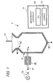
- FIG. 1 shows an arrangement of a part of a measuring apparatus according to the present invention.
- FIG. 1 shows a partial arrangement of a measuring apparatus 1 according to the present invention.
- the measuring apparatus of this embodiment comprises a preparing unit (dilution vessel) 51 in which a measuring sample is prepared, a supply route (supply passage) 27 which supplies a liquid material to the preparing unit in order to prepare the measuring sample, a withdrawing unit (not shown) which withdraws the measuring sample from the preparing unit 51 into the supply route 27, the measuring sample being prepared by supplying the liquid material to the preparing unit 51 via the supply route 27, and a measuring unit 85 which measures a predetermined physical property of the measuring sample withdrawn into the supply route 27 by the withdrawing unit.
- the measuring apparatus according to the present invention can measure the plasma glucose concentration and the glycohemoglobin concentration in order to diagnose diabetes.
- the measuring apparatus comprises therein all constitutive parts or components required for the purpose, including the measuring unit 85, a glucose measuring mechanism, a glycohemoglobin measuring mechanism, and a measurement control unit for processing the measured values supplied from the mechanisms (any one of them is not shown).
- the measuring unit 85 is an absorbance meter.
- the measuring sample is prepared in the dilution vessel 51, for example, such that a diluent (dilution liquid) and a hemolytic liquid (hemolytic agent) are mixed with a specimen (blood) as the analysis objective.
- the diluent and the hemolytic liquid are supplied to the dilution vessel 51 via the supply route 27 as described above.
- the measuring sample which is prepared in the dilution vessel 51, is subjected to respective analytical processes in the glucose measuring mechanism (not shown).
- the glucose measuring mechanism has a sensor unit (sensor), a power source unit (power source), and a current value measuring unit (current meter) (any one of them is not shown).
- the glucose measuring mechanism itself is provided in the dilution vessel 51.
- the sensor unit outputs the electrical physical quantity (current value) corresponding to the quantity or amount of electrons given and received with respect to glucose contained in the measuring sample.
- the sensor unit has an enzyme-immobilized layer in which glucose oxidoreductase is immobilized, and an electrode which gives and receives electrons with respect to the enzyme reaction product produced in the enzyme-immobilized layer.
- the sensor unit is installed on the wall surface of the dilution vessel 51 so that the enzyme-immobilized layer and the electrode are exposed to the measuring sample contained in the dilution vessel 51. The sensor unit can repeatedly measure glucose.
- oxidoreductase contained in the enzyme-immobilized layer include glucose oxidase (GOD) and glucose dehydrogenase (GDH).
- GOD glucose oxidase
- GDH glucose dehydrogenase
- the current value measuring unit measures the current between the electrodes, and the measured value is fed to the measurement control unit (measurement controller) 11.
- the measurement control unit In relation to the measurement of glucose, the measurement result of the absorbance, which is obtained at the absorption wavelength of hemoglobin by the absorbance meter 85, is also fed to the measurement control unit.
- the absorbance meter 85 is arranged on the supply route 27 in the vicinity of the connecting portion between the supply route 27 and the dilution vessel 51.
- the absorbance meter 85 can measure the absorbance of the liquid allowed to flow through the supply route 27 in the vicinal area.
- the absorbance meter 85 radiates the light having the absorption wavelength of hemoglobin onto the supply route 27 to measure the absorbance.
- the absorbance meter 85 has a light-emitting laser diode and a light-receiving photodiode.
- the light-emitting laser diode radiates the light onto the measuring sample allowed to flow through the supply route 27, and the light, which is transmitted through the measuring sample, is received by the light-receiving photodiode.
- the measurement control shown in FIG. 2 is realized by executing a program recorded in a memory included in the measurement controller 11 which is provided as the computer as well.
- the measurement controller 11 includes, at least, a central processing unit (CPU) 12 which is one of microprocessors, a storage (recording media) 13, and input/output units (I/O).
- the storage 13 includes memories, such as a read only memory (ROM) and a random access memory (RAM), for storing programs and data.
- the RAM is used as a work area for the CPU.
- the storage 13 may further include auxiliary storage unit(s), such as a hard disc for storing several data and/or programs.
- the CPU 12 loads the program stored in the ROM to the RAM and executes the program.
- the measurement controller controls operations of opening valves 57 and 58, a nozzle 14, the glucose measuring mechanism (sensor, power source, current meter), a pump 15, and the absorbance meter 85.
- the measurement control shown in FIG. 2 resides in the measuring process for the index in order to diagnose the diabetes. Specifically, the measurement control is executed by operating an operation panel provided distinctly for the measuring apparatus 1 by a user so that the instruction is given to start the measurement.
- the materials including, for example, the diluent and the hemolytic liquid are supplied to the dilution vessel 51 in order to prepare the measuring sample.
- the materials can be supplied directly into the dilution vessel 51 via the supply route 27.
- the dilution vessel 51 has an opening valve 57 and an opening valve 58.
- the opening valve 57 is in the valve-open state, and the opening valve 58 is in the valve-closed state.
- the opening valve 57 is in the valve-open state as described above, the mixture liquid of the standard hemolytic liquid and the diluent in a constant amount is supplied into the dilution vessel 51.
- the blood (whole blood), which is the analysis objective, is added to the dilution vessel 51 to which the materials have been supplied as described above, and the measuring sample is prepared thereby.
- a nozzle 14 which accommodates the blood, discharges the blood contained in the nozzle into the dilution vessel 51 after the process of S101 described above.
- the blood is mixed with the mixture liquid having been produced, and thus the measuring sample is prepared.
- S103 the stirring or agitation of the measuring sample is started.
- the agitation is performed by operation of an agitator (not shown) under control of the measurement controller 11.
- the agitation facilitates the hemolysis.
- S104 it is judged whether or not the hemolysis time Tr exceeds the reference hemolysis time Tr0. If the affirmative judgment is given in S104, the procedure proceeds to S105. If the negative judgment is given, the process of S104 is repeated again.
- the detected value obtained by the sensor unit of the glucose measuring mechanism i.e., the current value allowed to flow through the hydrogen peroxide electrode is acquired.
- the current value allowed to flow between the electrodes is measured by the current value measuring unit at the point in time at which the hemolysis time Tr arrives at the reference hemolysis time Tr0. The measured value is delivered to the measurement controller 11.
- S106 a part of the measuring sample contained in the dilution vessel 51 is withdrawn (pulled in) into the supply route 27.
- the pump 15, which is communicated with the dilution vessel 51 via the supply route 27, is installed in the analyzer (analyzing apparatus).
- the part of the measuring sample is withdrawn into the supply route 27 in accordance with the action of the pump 15.
- the hemoglobin concentration can be measured on the basis of the absorbance of the measuring sample measured by the absorbance meter 85 provided for the supply route 27.
- the diluent, with which the supply route 27 has been filled, is mixed with the measuring sample immediately after the execution of the withdrawal.
- the withdrawal is performed to such an extent that the mixture liquid is separated sufficiently far from the measuring area of the absorbance meter 85.
- the withdrawal of the measuring sample into the supply route 27 by the aid of the pump 15 corresponds to the withdrawal performed by the withdrawing unit according to the present invention.
- the absorbance of the measuring sample is measured at the absorption wavelength of hemoglobin by means of the absorbance meter 85, and the measured value is delivered to the measurement controller 11.
- the hemoglobin concentration of the measuring sample is calculated on the basis of the measured value.
- the hemoglobin concentration of the measuring sample is measured by the absorbance meter 85 when the plasma glucose concentration is calculated.
- the absorbance meter 85 measures the absorbance of the measuring sample such that the measuring light for the measurement is radiated onto the measuring sample from the light-emitting laser diode, and the light, which is transmitted through the measuring sample, is received by the light-receiving photodiode. Therefore, if any bubble is contained in the measuring sample, then the measuring light is scattered thereby, and it is difficult to measure the correct absorbance.
- the supply route 27 is always filled with any liquid. Therefore, the problem of the scattering of the measuring light, which is caused by the bubble as described above, is hardly caused. This feature will be explained in detail.
- the supply route 27 is filled with, for example, the diluent fed from, for example, a diluent bottle installed distinctly in the measuring apparatus.
- the measuring sample is merely prepared in the dilution vessel 51 as shown in FIG. 3B , and the phenomenon, in which any bubble appears in the supply route 27, is not caused.
- the measuring sample is withdrawn into the supply route 27 in order to measure the absorbance (during the process of S105 described above), as shown in FIG. 3C , the diluent does not exit but the measuring sample exists in the measuring area disposed inside the absorbance meter 85. In this situation, any bubble does not appear in the supply route 27 as well.
- the sufficient amount of the measuring sample is withdrawn into the supply route 27 during the withdrawal so that the mixture liquid of the diluent and the measuring sample does not exert any influence on the absorbance meter 85.
- the analysis process for the blood is completed, and the measurement control comes to the end (upon the completion of the process of S113 described above), then the interior of the supply route 27 is filled with the diluent again as shown in FIG. 3D . Also in this situation, the phenomenon, in which any bubble appears in the supply route 27, is not caused.
- the measuring sample which exists in the supply route 27, is fed to the dilution vessel 51 by means of the pump, and the liquid contained in the dilution vessel 51 is discharged by allowing the opening valve 58 to be in the valve-open state in the dilution vessel 51.
- the supply route 27 and the dilution vessel 51 are communicated with each other at the communication position 51a via the communication hole having the cross-sectional area which is extremely smaller than the cross-sectional area of the supply route 27. As shown in FIG.
- the communication hole has the small cross-sectional area to such an extent that the air does not invade into the supply route 27 when the liquid contained in the dilution vessel 51 is discharged, the liquid level thereof is lower than the communication position 51a, and the air is stored in the dilution vessel 51. Therefore, an appropriate value is adopted for the cross-sectional area of the communication hole on the basis of, for example, the physical property of the diluent, especially the viscosity thereof and the cross-sectional area of the supply route 27.
- the process of S113 is completed, then the interior of the supply route 27 is filled with the diluent again as shown in FIG. 3D , and any bubble does not make invasion thereinto from the side of the dilution vessel 51.
- the bubble is reliably suppressed in the supply route 27 for which the absorbance meter 85 is arranged when the measurement control is performed. Therefore, it is possible to reliably perform the measurement of the absorbance by the absorbance meter 85.
- This remarkable effect is provided owing to the fact that the absorbance meter 85 is arranged on the upstream side of the dilution vessel 51 in the direction in which the diluent is supplied in the supply route 27 as shown in FIGS. 1 and 3 . That is, the supply route 27, which supplies the diluent to the dilution vessel 51, is always filled with the diluent during the supply.
- the measuring sample which is produced in the dilution vessel 51 positioned on the downstream side from the absorbance meter 85, is intentionally withdrawn to the upstream side to measure the absorbance.
- the absorbance meter 85 can perform the appropriate or proper measurement.
- the sensor unit of the glucose measuring mechanism is provided in the dilution vessel 51 in combination.
- the sensor unit may be installed on the supply route 27 in the vicinity of the absorbance meter 85.
- the measuring sample is withdrawn into the supply route 27 in the vicinity of the absorbance meter 85. Therefore, even when the sensor unit is arranged on the supply route in the vicinity of the absorbance meter 85, it is possible to measure the correct plasma glucose concentration of blood in the same manner as in the embodiment described above.
- the sensor unit is installed on the supply route 27 between the absorbance meter 85 and the dilution vessel 51.
- the measurement of the plasma glucose concentration which is based on the use of the absorbance of the measuring sample as described above, is not limited to the macro size blood analyzer which uses, for example, the dilution vessel and the nozzle.
- the measurement of the plasma glucose concentration is also applicable to all types of blood analyzers including, for example, a blood analyzer which uses a microdevice.
- the flow passage, through which the sample or the like is allowed to flow has the widthwise dimension and the depth dimension which are formed in the order of micrometer. Accordingly, the liquid such as the sample or the like can be moved by utilizing the capillary phenomenon.
- the microdevice it is possible to miniaturize the blood analyzer.
- a microdevice shown in FIG. 4 realizes the measurement which is the same as or equivalent to the measurement of the plasma glucose concentration described in the foregoing embodiment. Specifically, a measuring sample, which is prepared by mixing blood as the analysis objective, a diluent, and a standard hemolytic liquid, is subjected to the measurement of the sample glucose concentration performed by an electrode based on the use of a GOD film (corresponding to the measurement performed by the sensor unit as described above) and the measurement performed by an optical system in order to measure the absorbance (corresponding to the measurement performed by the absorbance meter 85 as described above). Accordingly, the measurement of the plasma glucose concentration is finally realized.
- FIG. 4 mainly shows the construction of flow passages of the microdevice provided for the preparation of the measuring sample and the measurement of the plasma glucose concentration.
- a measuring device for measuring the physical property of the measuring sample
- a measuring area (measuring region) MR in which the measuring device is installed, is shown by dotted lines in FIG. 4 .
- the microdevice shown in FIG. 4 is formed such that a cover 100 is stacked on a substrate 110 formed with the flow passages, with an unillustrated joining sheet intervening therebetween.
- the cover 100 is formed, for example, such that the punching processing is applied to a transparent resin film, and then the resin film is cut to have an aimed size.
- a plurality of through-holes are formed to provide a first introducing port 101 into which the diluent is introduced, a second introducing port 102 into which the standard hemolytic liquid is introduced, a blood introducing port 103 into which the blood is introduced, and air vent holes 104, 105.
- the punching processing is applied after cutting the resin film to form the cover 100 as well. It is preferable that a hydrophilic or water-attracting treatment is applied to one surface of the cover 100, for example, by applying a surfactant or radiating the ultraviolet ray.
- the flow passages which have recess-shaped cross sections, are formed on the substrate 110.
- the flow passages, which are formed on the substrate 110, include a first supply flow passage 111, a second supply flow passage 112, a blood supply flow passage 113, and a diluting flow passage 114.
- the diluent is introduced from the first introducing port 101
- the standard hemolytic liquid is introduced from the second introducing port 102
- the blood is introduced from the blood introducing port 103.
- These liquids are allowed to flow through the first supply flow passage 111, the second supply flow passage 112, and the blood supply flow passage 113 respectively in accordance with the capillary phenomenon.
- the first supply flow passage 111, the second supply flow passage 112, and the blood supply flow passage 113 are connected to an end portion 114a of the diluting flow passage 114 respectively.
- the diluting flow passage 114 is formed to have a meander shape which meanders in a bellows form. Accordingly, the mixing of the blood, the diluent, and the standard hemolytic liquid is accelerated.
- a recessed portion 114b and a recessed portion 114c which can store predetermined amounts of the liquid, are arranged in series in the flow passage after passing through an end portion 114d of the diluting flow passage 114.
- the recessed portion 114b functions as a mixing chamber for the blood, the diluent, and the standard hemolytic liquid, wherein the measuring sample, which is allowed to flow thereinto via the diluting flow passage 114, is temporarily stored, and the measuring sample is mixed equivalently or uniformly.
- the measuring sample is finally prepared in the recessed portion 114b.
- the corresponding air vent holes 104, 105, which are formed through the cover 100, are arranged on the recessed portion 114b and the recessed portion 114c when the microdevice is formed.
- the measuring sample which is prepared in the recessed portion 114b, is subjected to the counterflow to the diluting flow passage 114 by means of the external force such as the centrifugal force or the like.
- the measuring sample passes through the measuring area MR.
- the measuring device for measuring the plasma glucose concentration i.e., the measuring device corresponding to the sensor unit and/or the absorbance meter 85 of the embodiment described above, which is installed for the measuring area MR, can measure the physical property of the measuring sample in order to measure the plasma glucose concentration without being affected by any bubble in the measuring sample.
- the diluent is allowed to flow into the diluting flow passage 114. Accordingly, the entire flow passages are washed to perform the preparation of the next measuring sample and the preparation for the measurement.
- the flow control is performed such that the measuring sample, which is prepared in the recessed portion 114b, is once allowed to flow toward the recessed portion 114c, and then the measuring sample, which is contained in the recessed portion 114b, is withdrawn toward the measuring area MR.
- the recessed portion 114c functions as a bubble trap section which traps the bubble contained in the measuring sample.
- the measuring apparatuses according to the first embodiment and the first and second modified embodiments described above are provided with the arrangement in which the measuring sample is withdrawn into the measuring area of the supply route 27 (diluting flow passage 114). According to this arrangement, it is possible to solve the problem of the invasion of a bubble into the measuring area as described above, while the following advantages can be obtained.
- the diluent is supplied to the supply route 27 (diluting flow passage 114) after the completion of the measurement of, for example, the absorbance. Accordingly, the measured measuring sample, which has been withdrawn into (allowed to stay in) the supply route 27 (diluting flow passage 114), can be forcibly allowed to flow toward the downstream side. In other words, the supply route 27 (diluting flow passage 114) can be washed with the diluent.
- the baseline measurement is also applicable in relation to the color measurement for a sample based on the transmitted light obtained by transmitting the measuring light through the measuring sample and the concentration measurement for a predetermined component by utilizing the transmitted light as performed in the liquid chromatography.
- the supply route 27 (diluting flow passage 114), which is the flow passage for introducing the diluent, also serves as the flow passage for inducing or guiding the measuring sample to the measuring area. Therefore, it is unnecessary to form any inducing flow passage for the measuring sample different from the flow passage for introducing the diluent. This advantage contributes to the miniaturization and the simplification of the measuring apparatus.
- any inducing flow passage for the measuring sample which is different from the flow passage for introducing the diluent, it is conceived to miniaturize and simplify the measuring apparatus by using the inducing flow passage as the discharging flow passage for discharging the measuring sample as well.
- the measuring sample (waste liquid), which is to be discharged, is discharged while passing through the inducing flow passage. Therefore, the interior of the inducing flow passage is in a state of being dirtied by the residue (for example, blood serum).
- the measuring sample which is in the amount required for the measurement, is induced or guided to the flow passage for introducing the diluent (supply route 27, diluting flow passage 114). Therefore, it is possible to reduce the amount of the measuring sample allowed to flow through the flow passage for the measurement, and it is possible to suppress the interior of the flow passage from being dirtied.
- the present invention includes, in an embodiment thereof, a computer program for performing the measurement control. Further, a medium, in which the program is recorded on the recording medium readable by the computer, also belongs to the category or concept of the present invention. As for the recording medium in which the program is recorded, the measurement control as described above can be performed by reading and executing the program of the recording medium by a computer.
- the recording medium which is readable by the computer, herein refers to the recording medium in which the information including, for example, the data and the program is stored in accordance with the electrical, magnetic, optical, mechanical, or chemical function, and the information can be read therefrom by the computer.
- the recording medium as described above, which are removable from the computer are exemplified, for example, by the floppy disk (trade name), the magneto-optical disk, CD-ROM, CD-R/W, DVD, Blu-ray Disk, DAT, 8 mm tape, and the memory card.
- Those provided as the recording medium, which are fixed to the computer are exemplified, for example, by the hard disk and ROM (Read Only Memory).
Landscapes
- Chemical & Material Sciences (AREA)
- Health & Medical Sciences (AREA)
- Analytical Chemistry (AREA)
- General Health & Medical Sciences (AREA)
- Immunology (AREA)
- Hematology (AREA)
- Life Sciences & Earth Sciences (AREA)
- General Physics & Mathematics (AREA)
- Physics & Mathematics (AREA)
- Pathology (AREA)
- Dispersion Chemistry (AREA)
- Biochemistry (AREA)
- Clinical Laboratory Science (AREA)
- Chemical Kinetics & Catalysis (AREA)
- Investigating Or Analysing Materials By Optical Means (AREA)
- Investigating Or Analysing Biological Materials (AREA)
- Sampling And Sample Adjustment (AREA)
- Automatic Analysis And Handling Materials Therefor (AREA)
Claims (15)
- Appareil de mesure pour mesurer une propriété physique prédéterminée d'un échantillon de mesure liquide, l'appareil de mesure comprenant :une unité de préparation (51) pour préparer l'échantillon de mesure liquide ; etune voie d'alimentation (27) raccordée à l'unité de préparation (51) et configurée pour alimenter l'unité de préparation (51) en matière liquide afin de préparer l'échantillon de mesure liquide ;caractérisé parune unité de retrait configurée pour retirer l'échantillon de mesure liquide de l'unité de préparation (51) jusque dans la voie d'alimentation (27) ; etune unité de mesure (85) installée sur la voie d'alimentation (27) ;dans lequel l'unité de mesure (85) est configurée pour mesurer la propriété physique prédéterminée de l'échantillon de mesure liquide retiré jusque dans la voie d'alimentation (27) par l'unité de retrait.
- Appareil de mesure selon la revendication 1, dans lequel l'unité de mesure (85) est configurée pour mesurer la propriété physique prédéterminée de l'échantillon de mesure liquide au moyen de moyens optiques.
- Appareil de mesure selon la revendication 1 ou 2, dans lequel l'unité de retrait est configurée pour retirer l'échantillon de mesure liquide de l'unité de préparation (51) de sorte qu'un liquide de mélange de l'échantillon de mesure liquide et de la matière liquide contenue dans la voie d'alimentation (27), qui est produit lorsque l'échantillon de mesure liquide est retiré jusque dans la voie d'alimentation (27), soit déplacé au-delà d'une zone de mesure prédéterminée disposée dans la voie d'alimentation (27) afin de réaliser la mesure par l'unité de mesure (85).
- Appareil de mesure selon l'une quelconque des revendications 1 à 3, comprenant en outre :une section d'évacuation de voie d'alimentation configurée pour évacuer l'échantillon de mesure liquide existant dans la voie d'alimentation (27) vers l'unité de préparation (51) après la mesure de la propriété physique prédéterminée de l'échantillon de mesure liquide par l'unité de mesure (85) ; etune section d'évacuation d'unité de préparation configurée pour évacuer tout liquide contenu dans l'unité de préparation (51) vers l'extérieur de l'unité de préparation (51) après l'évacuation effectuée par la section d'évacuation de voie d'alimentation ou en synchronisation avec celle-ci ; et, éventuellement dans lequel la voie d'alimentation (27) et l'unité de préparation (51) sont mises en communication l'une avec l'autre via un trou de communication qui a une aire en coupe prédéterminée de sorte que tout l'air contenu dans l'unité de préparation (51) n'entre pas dans la voie d'alimentation (27) lorsque l'évacuation par la section d'évacuation de voie d'alimentation est achevée, le liquide contenu dans l'unité de préparation (51) est évacué par la section d'évacuation d'unité de préparation, et un niveau de liquide dans l'unité de préparation (51) est inférieur à une position de communication entre la voie d'alimentation (27) et l'unité de préparation (51).
- Appareil de mesure selon l'une quelconque des revendications 1 à 5, configuré pour préparer l'échantillon de mesure liquide par mélange, dans l'unité de préparation (51), de sang, d'un agent hémolytique qui hémolyse le sang, et d'un diluant qui est fourni en tant que matière liquide via la voie d'alimentation (27) à l'unité de préparation (51) et qui dilue le sang.
- Appareil de mesure selon la revendication 5, dans lequel l'unité de mesure (85) est configurée pour mesurer une concentration d'hémoglobine dans l'échantillon de mesure liquide retiré jusque dans la voie d'alimentation (27) par l'unité de retrait, en tant que propriété physique prédéterminée au moyen de moyens optiques.
- Appareil de mesure selon la revendication 6, comprenant en outre :une unité de mesure de concentration de glucose d'échantillon configurée pour mesurer une concentration de glucose de l'échantillon de mesure liquide ; etune unité de calcul de concentration de glucose plasmatique configurée pour calculer une concentration de glucose plasmatique du sang sur la base de la concentration de glucose mesurée par l'unité de mesure de concentration de glucose d'échantillon et de la concentration d'hémoglobine mesurée par l'unité de mesure (85).
- Appareil de mesure selon la revendication 7, dans lequel l'unité de mesure de concentration de glucose d'échantillon est configurée pour mesurer la concentration de glucose de l'échantillon de mesure liquide contenu dans l'unité de préparation (51).
- Appareil de mesure selon la revendication 7, dans lequel l'unité de mesure de concentration de glucose d'échantillon est configurée pour mesurer la concentration de glucose de l'échantillon de mesure liquide dans la voie d'alimentation (27), et, éventuellement, dans lequel l'unité de mesure de concentration de glucose d'échantillon est installée dans la voie d'alimentation (27) entre l'unité de mesure (85) et l'unité de préparation (51).
- Procédé de mesure pour mesurer une propriété physique prédéterminée d'un échantillon de mesure liquide préparé dans une unité de préparation (51), le procédé de mesure comprenant :l'alimentation de l'unité de préparation (51) en matière liquide via une voie d'alimentation (27) raccordée à l'unité de préparation (51), de sorte que l'échantillon de mesure liquide soit préparé par alimentation de l'unité de préparation (51) en matière liquide via la voie d'alimentation (27) ;une étape de retrait consistant à retirer l'échantillon de mesure liquide de l'unité de préparation (51) jusque dans la voie d'alimentation (27) ; etune étape de mesure consistant à mesurer la propriété physique prédéterminée de l'échantillon de mesure liquide retiré jusque dans la voie d'alimentation (27) à l'étape de retrait à l'aide d'une unité de mesure (85) installée sur la voie d'alimentation (27).
- Procédé de mesure selon la revendication 10, dans lequel la propriété physique prédéterminée de l'échantillon de mesure liquide est mesurée par des moyens optiques à l'étape de mesure.
- Procédé de mesure selon la revendication 10 ou 11, comprenant en outre :une étape d'évacuation de voie d'alimentation consistant à évacuer l'échantillon de mesure liquide existant dans la voie d'alimentation (27) vers l'unité de préparation (51) après la mesure de la propriété physique prédéterminée de l'échantillon de mesure liquide à l'étape de mesure ; etune étape d'évacuation d'unité de préparation consistant à évacuer tout liquide contenu dans l'unité de préparation vers l'extérieur de l'unité de préparation après l'évacuation réalisée à l'étape d'évacuation de voie d'alimentation ou en synchronisation avec celle-ci.
- Programme d'ordinateur comprenant des instructions pour amener un appareil de mesure selon la revendication 1 à exécuter le procédé de la revendication 10.
- Programme d'ordinateur selon la revendication 13, comprenant des instructions pour amener l'appareil de mesure à exécuter en outre :une étape d'évacuation de voie d'alimentation (27) consistant à évacuer l'échantillon de mesure liquide existant dans la voie d'alimentation (27) vers l'unité de préparation (51) après la mesure de la propriété physique prédéterminée de l'échantillon de mesure liquide à l'étape de mesure ; etune étape d'évacuation d'unité de préparation (51) consistant à évacuer tout liquide contenu dans l'unité de préparation (51) vers l'extérieur de l'unité de préparation (51) en synchronisation avec l'évacuation de l'échantillon de mesure liquide de la voie d'alimentation (27).
- Support d'enregistrement lisible par ordinateur sur lequel est stocké le programme d'ordinateur tel que défini à la revendication 13 ou 14.
Applications Claiming Priority (2)
| Application Number | Priority Date | Filing Date | Title |
|---|---|---|---|
| JP2010142244 | 2010-06-23 | ||
| JP2011137934A JP5888885B2 (ja) | 2010-06-23 | 2011-06-22 | 測定装置、測定方法、測定プログラム、および測定システム |
Publications (3)
| Publication Number | Publication Date |
|---|---|
| EP2400285A2 EP2400285A2 (fr) | 2011-12-28 |
| EP2400285A3 EP2400285A3 (fr) | 2015-04-29 |
| EP2400285B1 true EP2400285B1 (fr) | 2020-06-03 |
Family
ID=44534843
Family Applications (1)
| Application Number | Title | Priority Date | Filing Date |
|---|---|---|---|
| EP11171233.7A Active EP2400285B1 (fr) | 2010-06-23 | 2011-06-23 | Appareil de mesure pour mesurer une propriété physique d'un échantillon |
Country Status (4)
| Country | Link |
|---|---|
| US (1) | US8712702B2 (fr) |
| EP (1) | EP2400285B1 (fr) |
| JP (1) | JP5888885B2 (fr) |
| CN (1) | CN102368073B (fr) |
Families Citing this family (1)
| Publication number | Priority date | Publication date | Assignee | Title |
|---|---|---|---|---|
| JP5806884B2 (ja) * | 2010-09-24 | 2015-11-10 | 株式会社堀場製作所 | 全血免疫測定装置及び全血免疫測定方法 |
Citations (1)
| Publication number | Priority date | Publication date | Assignee | Title |
|---|---|---|---|---|
| BE1004241A7 (fr) * | 1990-01-26 | 1992-10-20 | Robaut S C | Dispositif d'analyse d'un echantillon de liquide et procede utilisant un tel dispositif. |
Family Cites Families (25)
| Publication number | Priority date | Publication date | Assignee | Title |
|---|---|---|---|---|
| US4293413A (en) * | 1979-12-28 | 1981-10-06 | Baxter Travenol Laboratories, Inc. | Dialyzer blood circuit and bubble traps |
| JPS57153248A (en) * | 1981-03-18 | 1982-09-21 | Hitachi Ltd | Flow cell |
| JPS59168371A (ja) * | 1983-03-16 | 1984-09-22 | Hitachi Ltd | 血液生化学成分の分析方法およびその装置 |
| ES2049254T3 (es) * | 1987-08-27 | 1994-04-16 | Biotrack Inc | Aparato y procedimiento para la dilucion y mezcla de muestras liquidas. |
| JPH02159563A (ja) * | 1988-12-12 | 1990-06-19 | Hitachi Ltd | 診断システム |
| JPH0737991B2 (ja) | 1989-07-13 | 1995-04-26 | 株式会社京都第一科学 | グルコース濃度の測定方法 |
| US5272060A (en) | 1989-07-13 | 1993-12-21 | Kyoto Daiichi Kagaku Co., Ltd. | Method for determination of glucose concentration in whole blood |
| JPH0737991A (ja) | 1993-07-23 | 1995-02-07 | Sony Corp | 半導体集積回路とその製造方法 |
| JP3687789B2 (ja) * | 1994-09-13 | 2005-08-24 | 東陶機器株式会社 | 物質濃度計測装置 |
| JP3700140B2 (ja) | 1995-07-21 | 2005-09-28 | アークレイ株式会社 | グルコース濃度の測定方法 |
| JP3698281B2 (ja) | 1996-05-29 | 2005-09-21 | アークレイ株式会社 | グルコース濃度の測定方法 |
| US5998184A (en) * | 1997-10-08 | 1999-12-07 | Unisyn Technologies, Inc. | Basket-type bioreactor |
| SE518539C2 (sv) * | 2000-06-28 | 2002-10-22 | Migrata U K Ltd | Sätt och kyvett för kvantitativ hemoglobinbestämning i outspätt helblod |
| CN1295243A (zh) * | 2000-12-12 | 2001-05-16 | 吴斌 | 用生化酶标多功能分析仪测试血红蛋白检测技术的方法 |
| US7041174B2 (en) * | 2003-02-19 | 2006-05-09 | Sunmodics,Inc. | Grafting apparatus and method of using |
| US8508713B2 (en) * | 2004-06-10 | 2013-08-13 | Nikon Corporation | Exposure apparatus, exposure method, and method for producing device |
| CN101048657B (zh) * | 2004-10-28 | 2012-06-06 | 爱科来株式会社 | 血液试样的特定成分的浓度测定方法和浓度测定装置 |
| JP4622836B2 (ja) * | 2005-12-08 | 2011-02-02 | 王子製紙株式会社 | 分析装置 |
| US20090123337A1 (en) * | 2005-06-24 | 2009-05-14 | Arkray,Inc | Cartridge |
| FR2891911B1 (fr) * | 2005-10-07 | 2008-04-25 | Horiba Abx Sas Soc Par Actions | "dispositif modulaire destine a l'analyse d'un fluide biologique, notamment sanguin" |
| EP2049882A1 (fr) * | 2006-07-20 | 2009-04-22 | Trinean NV | Procédés et systèmes de caractérisation optique |
| JP2008035748A (ja) | 2006-08-03 | 2008-02-21 | Toyobo Co Ltd | アスペルギルス属菌由来新規グルコースデヒドロゲナーゼ |
| US9429579B2 (en) * | 2006-09-22 | 2016-08-30 | Arkray, Inc. | Blood analysis apparatus |
| JP4901956B2 (ja) * | 2007-04-25 | 2012-03-21 | アークレイ株式会社 | 基質濃度測定方法および基質濃度測定装置 |
| WO2010092883A1 (fr) * | 2009-02-12 | 2010-08-19 | アークレイ株式会社 | Procédé d'analyse, dispositif d'analyse, programme utilisé pour mettre en oeuvre ledit procédé d'analyse et support de stockage et dispositif d'extraction pour ce programme |
-
2011
- 2011-06-22 JP JP2011137934A patent/JP5888885B2/ja active Active
- 2011-06-23 CN CN201110181222.4A patent/CN102368073B/zh active Active
- 2011-06-23 EP EP11171233.7A patent/EP2400285B1/fr active Active
- 2011-06-23 US US13/167,585 patent/US8712702B2/en active Active
Patent Citations (1)
| Publication number | Priority date | Publication date | Assignee | Title |
|---|---|---|---|---|
| BE1004241A7 (fr) * | 1990-01-26 | 1992-10-20 | Robaut S C | Dispositif d'analyse d'un echantillon de liquide et procede utilisant un tel dispositif. |
Also Published As
| Publication number | Publication date |
|---|---|
| CN102368073A (zh) | 2012-03-07 |
| JP2012027013A (ja) | 2012-02-09 |
| US20120158314A1 (en) | 2012-06-21 |
| US8712702B2 (en) | 2014-04-29 |
| JP5888885B2 (ja) | 2016-03-22 |
| CN102368073B (zh) | 2014-10-22 |
| EP2400285A3 (fr) | 2015-04-29 |
| EP2400285A2 (fr) | 2011-12-28 |
Similar Documents
| Publication | Publication Date | Title |
|---|---|---|
| EP2437069B1 (fr) | Analyseur et procédé d'analyse | |
| KR101352900B1 (ko) | 조작성이 향상된 생화학 분석 카트리지 | |
| EP2233910B1 (fr) | Analysateur de sang, procédé d'analyse de sang et produit de programme d'ordinateur | |
| US8252235B2 (en) | Monitoring method, monitoring apparatus, and liquid sample analyzer | |
| US20130260415A1 (en) | Sample analyzer and method for controlling a sample analyzer | |
| JP5812701B2 (ja) | 血漿グルコース測定方法 | |
| JP5951545B2 (ja) | 検体分析装置、検体分析方法、及びコンピュータプログラム | |
| US9795967B2 (en) | Sample analyzer and reagent container | |
| EP3404419A1 (fr) | Analyseur automatisé et son procédé de commande | |
| CN104251912A (zh) | 试样处理装置以及试样处理装置的异常检测方法 | |
| US20130164778A1 (en) | Two step sample loading of a fluid analysis cartridge | |
| EP3485459B1 (fr) | Système et procédé de détection optique d'hémolyse de sang total | |
| US20090238724A1 (en) | Disc for analyzing sample | |
| US8712702B2 (en) | Measuring apparatus for measuring a physical property of a sample | |
| JP5312834B2 (ja) | 血液凝固分析装置、血液凝固分析方法、及び、コンピュータプログラム | |
| JP5312835B2 (ja) | 血液凝固分析装置、血液凝固分析方法、及びコンピュータプログラム | |
| CN121090505A (zh) | 传感器组件和多孔膜传感器元件 | |
| JP5140491B2 (ja) | 自動分析装置および分注精度確認方法 | |
| US20190302017A1 (en) | Reaction system and reaction method | |
| CN116324407A (zh) | 用于确定血红蛋白浓度的竖直流动测定设备和方法 | |
| KR101762877B1 (ko) | 혈액과 시약의 혼합장치 | |
| KR20150066722A (ko) | 검사장치 및 검사방법 | |
| JP5806514B2 (ja) | 自動分析装置 | |
| Seeger et al. | Analytical performance of the ABL90 FLEX blood gas analyzer | |
| CN114829910B (zh) | 多孔膜传感器组件 |
Legal Events
| Date | Code | Title | Description |
|---|---|---|---|
| AK | Designated contracting states |
Kind code of ref document: A2 Designated state(s): AL AT BE BG CH CY CZ DE DK EE ES FI FR GB GR HR HU IE IS IT LI LT LU LV MC MK MT NL NO PL PT RO RS SE SI SK SM TR |
|
| AX | Request for extension of the european patent |
Extension state: BA ME |
|
| PUAI | Public reference made under article 153(3) epc to a published international application that has entered the european phase |
Free format text: ORIGINAL CODE: 0009012 |
|
| PUAL | Search report despatched |
Free format text: ORIGINAL CODE: 0009013 |
|
| AK | Designated contracting states |
Kind code of ref document: A3 Designated state(s): AL AT BE BG CH CY CZ DE DK EE ES FI FR GB GR HR HU IE IS IT LI LT LU LV MC MK MT NL NO PL PT RO RS SE SI SK SM TR |
|
| AX | Request for extension of the european patent |
Extension state: BA ME |
|
| RIC1 | Information provided on ipc code assigned before grant |
Ipc: G01N 35/10 20060101ALN20150323BHEP Ipc: B01L 3/00 20060101ALI20150323BHEP Ipc: G01N 1/38 20060101AFI20150323BHEP Ipc: G01N 33/49 20060101ALI20150323BHEP Ipc: G01N 21/05 20060101ALN20150323BHEP |
|
| RAP1 | Party data changed (applicant data changed or rights of an application transferred) |
Owner name: ARKRAY, INC. |
|
| 17P | Request for examination filed |
Effective date: 20151029 |
|
| RBV | Designated contracting states (corrected) |
Designated state(s): AL AT BE BG CH CY CZ DE DK EE ES FI FR GB GR HR HU IE IS IT LI LT LU LV MC MK MT NL NO PL PT RO RS SE SI SK SM TR |
|
| STAA | Information on the status of an ep patent application or granted ep patent |
Free format text: STATUS: EXAMINATION IS IN PROGRESS |
|
| 17Q | First examination report despatched |
Effective date: 20171023 |
|
| GRAP | Despatch of communication of intention to grant a patent |
Free format text: ORIGINAL CODE: EPIDOSNIGR1 |
|
| STAA | Information on the status of an ep patent application or granted ep patent |
Free format text: STATUS: GRANT OF PATENT IS INTENDED |
|
| RIC1 | Information provided on ipc code assigned before grant |
Ipc: G01N 33/49 20060101ALI20191125BHEP Ipc: B01L 3/00 20060101ALI20191125BHEP Ipc: G01N 1/38 20060101AFI20191125BHEP Ipc: G01N 21/05 20060101ALN20191125BHEP Ipc: G01N 35/10 20060101ALN20191125BHEP |
|
| INTG | Intention to grant announced |
Effective date: 20191217 |
|
| RIN1 | Information on inventor provided before grant (corrected) |
Inventor name: KAMATA, TATSUO Inventor name: TAKAGI, TAKESHI Inventor name: OKUMURA, KOJI |
|
| GRAS | Grant fee paid |
Free format text: ORIGINAL CODE: EPIDOSNIGR3 |
|
| GRAA | (expected) grant |
Free format text: ORIGINAL CODE: 0009210 |
|
| STAA | Information on the status of an ep patent application or granted ep patent |
Free format text: STATUS: THE PATENT HAS BEEN GRANTED |
|
| AK | Designated contracting states |
Kind code of ref document: B1 Designated state(s): AL AT BE BG CH CY CZ DE DK EE ES FI FR GB GR HR HU IE IS IT LI LT LU LV MC MK MT NL NO PL PT RO RS SE SI SK SM TR |
|
| REG | Reference to a national code |
Ref country code: GB Ref legal event code: FG4D |
|
| RIN1 | Information on inventor provided before grant (corrected) |
Inventor name: OKUMURA, KOJI Inventor name: TAKAGI, TAKESHI Inventor name: KAMATA, TATSUO |
|
| REG | Reference to a national code |
Ref country code: CH Ref legal event code: EP Ref country code: AT Ref legal event code: REF Ref document number: 1277508 Country of ref document: AT Kind code of ref document: T Effective date: 20200615 |
|
| REG | Reference to a national code |
Ref country code: DE Ref legal event code: R096 Ref document number: 602011067103 Country of ref document: DE |
|
| REG | Reference to a national code |
Ref country code: LT Ref legal event code: MG4D |
|
| PG25 | Lapsed in a contracting state [announced via postgrant information from national office to epo] |
Ref country code: LT Free format text: LAPSE BECAUSE OF FAILURE TO SUBMIT A TRANSLATION OF THE DESCRIPTION OR TO PAY THE FEE WITHIN THE PRESCRIBED TIME-LIMIT Effective date: 20200603 Ref country code: FI Free format text: LAPSE BECAUSE OF FAILURE TO SUBMIT A TRANSLATION OF THE DESCRIPTION OR TO PAY THE FEE WITHIN THE PRESCRIBED TIME-LIMIT Effective date: 20200603 Ref country code: NO Free format text: LAPSE BECAUSE OF FAILURE TO SUBMIT A TRANSLATION OF THE DESCRIPTION OR TO PAY THE FEE WITHIN THE PRESCRIBED TIME-LIMIT Effective date: 20200903 Ref country code: GR Free format text: LAPSE BECAUSE OF FAILURE TO SUBMIT A TRANSLATION OF THE DESCRIPTION OR TO PAY THE FEE WITHIN THE PRESCRIBED TIME-LIMIT Effective date: 20200904 Ref country code: SE Free format text: LAPSE BECAUSE OF FAILURE TO SUBMIT A TRANSLATION OF THE DESCRIPTION OR TO PAY THE FEE WITHIN THE PRESCRIBED TIME-LIMIT Effective date: 20200603 |
|
| REG | Reference to a national code |
Ref country code: NL Ref legal event code: MP Effective date: 20200603 |
|
| PG25 | Lapsed in a contracting state [announced via postgrant information from national office to epo] |
Ref country code: BG Free format text: LAPSE BECAUSE OF FAILURE TO SUBMIT A TRANSLATION OF THE DESCRIPTION OR TO PAY THE FEE WITHIN THE PRESCRIBED TIME-LIMIT Effective date: 20200903 Ref country code: RS Free format text: LAPSE BECAUSE OF FAILURE TO SUBMIT A TRANSLATION OF THE DESCRIPTION OR TO PAY THE FEE WITHIN THE PRESCRIBED TIME-LIMIT Effective date: 20200603 Ref country code: HR Free format text: LAPSE BECAUSE OF FAILURE TO SUBMIT A TRANSLATION OF THE DESCRIPTION OR TO PAY THE FEE WITHIN THE PRESCRIBED TIME-LIMIT Effective date: 20200603 Ref country code: LV Free format text: LAPSE BECAUSE OF FAILURE TO SUBMIT A TRANSLATION OF THE DESCRIPTION OR TO PAY THE FEE WITHIN THE PRESCRIBED TIME-LIMIT Effective date: 20200603 |
|
| REG | Reference to a national code |
Ref country code: AT Ref legal event code: MK05 Ref document number: 1277508 Country of ref document: AT Kind code of ref document: T Effective date: 20200603 |
|
| PG25 | Lapsed in a contracting state [announced via postgrant information from national office to epo] |
Ref country code: AL Free format text: LAPSE BECAUSE OF FAILURE TO SUBMIT A TRANSLATION OF THE DESCRIPTION OR TO PAY THE FEE WITHIN THE PRESCRIBED TIME-LIMIT Effective date: 20200603 Ref country code: NL Free format text: LAPSE BECAUSE OF FAILURE TO SUBMIT A TRANSLATION OF THE DESCRIPTION OR TO PAY THE FEE WITHIN THE PRESCRIBED TIME-LIMIT Effective date: 20200603 |
|
| PG25 | Lapsed in a contracting state [announced via postgrant information from national office to epo] |
Ref country code: SM Free format text: LAPSE BECAUSE OF FAILURE TO SUBMIT A TRANSLATION OF THE DESCRIPTION OR TO PAY THE FEE WITHIN THE PRESCRIBED TIME-LIMIT Effective date: 20200603 Ref country code: EE Free format text: LAPSE BECAUSE OF FAILURE TO SUBMIT A TRANSLATION OF THE DESCRIPTION OR TO PAY THE FEE WITHIN THE PRESCRIBED TIME-LIMIT Effective date: 20200603 Ref country code: AT Free format text: LAPSE BECAUSE OF FAILURE TO SUBMIT A TRANSLATION OF THE DESCRIPTION OR TO PAY THE FEE WITHIN THE PRESCRIBED TIME-LIMIT Effective date: 20200603 Ref country code: ES Free format text: LAPSE BECAUSE OF FAILURE TO SUBMIT A TRANSLATION OF THE DESCRIPTION OR TO PAY THE FEE WITHIN THE PRESCRIBED TIME-LIMIT Effective date: 20200603 Ref country code: CZ Free format text: LAPSE BECAUSE OF FAILURE TO SUBMIT A TRANSLATION OF THE DESCRIPTION OR TO PAY THE FEE WITHIN THE PRESCRIBED TIME-LIMIT Effective date: 20200603 Ref country code: RO Free format text: LAPSE BECAUSE OF FAILURE TO SUBMIT A TRANSLATION OF THE DESCRIPTION OR TO PAY THE FEE WITHIN THE PRESCRIBED TIME-LIMIT Effective date: 20200603 Ref country code: PT Free format text: LAPSE BECAUSE OF FAILURE TO SUBMIT A TRANSLATION OF THE DESCRIPTION OR TO PAY THE FEE WITHIN THE PRESCRIBED TIME-LIMIT Effective date: 20201006 |
|
| REG | Reference to a national code |
Ref country code: CH Ref legal event code: PL |
|
| PG25 | Lapsed in a contracting state [announced via postgrant information from national office to epo] |
Ref country code: PL Free format text: LAPSE BECAUSE OF FAILURE TO SUBMIT A TRANSLATION OF THE DESCRIPTION OR TO PAY THE FEE WITHIN THE PRESCRIBED TIME-LIMIT Effective date: 20200603 Ref country code: SK Free format text: LAPSE BECAUSE OF FAILURE TO SUBMIT A TRANSLATION OF THE DESCRIPTION OR TO PAY THE FEE WITHIN THE PRESCRIBED TIME-LIMIT Effective date: 20200603 Ref country code: IS Free format text: LAPSE BECAUSE OF FAILURE TO SUBMIT A TRANSLATION OF THE DESCRIPTION OR TO PAY THE FEE WITHIN THE PRESCRIBED TIME-LIMIT Effective date: 20201003 |
|
| REG | Reference to a national code |
Ref country code: DE Ref legal event code: R097 Ref document number: 602011067103 Country of ref document: DE |
|
| PG25 | Lapsed in a contracting state [announced via postgrant information from national office to epo] |
Ref country code: MC Free format text: LAPSE BECAUSE OF FAILURE TO SUBMIT A TRANSLATION OF THE DESCRIPTION OR TO PAY THE FEE WITHIN THE PRESCRIBED TIME-LIMIT Effective date: 20200603 Ref country code: LU Free format text: LAPSE BECAUSE OF NON-PAYMENT OF DUE FEES Effective date: 20200623 |
|
| PLBE | No opposition filed within time limit |
Free format text: ORIGINAL CODE: 0009261 |
|
| STAA | Information on the status of an ep patent application or granted ep patent |
Free format text: STATUS: NO OPPOSITION FILED WITHIN TIME LIMIT |
|
| REG | Reference to a national code |
Ref country code: BE Ref legal event code: MM Effective date: 20200630 |
|
| PG25 | Lapsed in a contracting state [announced via postgrant information from national office to epo] |
Ref country code: CH Free format text: LAPSE BECAUSE OF NON-PAYMENT OF DUE FEES Effective date: 20200630 Ref country code: DK Free format text: LAPSE BECAUSE OF FAILURE TO SUBMIT A TRANSLATION OF THE DESCRIPTION OR TO PAY THE FEE WITHIN THE PRESCRIBED TIME-LIMIT Effective date: 20200603 Ref country code: IE Free format text: LAPSE BECAUSE OF NON-PAYMENT OF DUE FEES Effective date: 20200623 Ref country code: LI Free format text: LAPSE BECAUSE OF NON-PAYMENT OF DUE FEES Effective date: 20200630 |
|
| 26N | No opposition filed |
Effective date: 20210304 |
|
| PG25 | Lapsed in a contracting state [announced via postgrant information from national office to epo] |
Ref country code: BE Free format text: LAPSE BECAUSE OF NON-PAYMENT OF DUE FEES Effective date: 20200630 Ref country code: SI Free format text: LAPSE BECAUSE OF FAILURE TO SUBMIT A TRANSLATION OF THE DESCRIPTION OR TO PAY THE FEE WITHIN THE PRESCRIBED TIME-LIMIT Effective date: 20200603 |
|
| PG25 | Lapsed in a contracting state [announced via postgrant information from national office to epo] |
Ref country code: TR Free format text: LAPSE BECAUSE OF FAILURE TO SUBMIT A TRANSLATION OF THE DESCRIPTION OR TO PAY THE FEE WITHIN THE PRESCRIBED TIME-LIMIT Effective date: 20200603 Ref country code: MT Free format text: LAPSE BECAUSE OF FAILURE TO SUBMIT A TRANSLATION OF THE DESCRIPTION OR TO PAY THE FEE WITHIN THE PRESCRIBED TIME-LIMIT Effective date: 20200603 Ref country code: CY Free format text: LAPSE BECAUSE OF FAILURE TO SUBMIT A TRANSLATION OF THE DESCRIPTION OR TO PAY THE FEE WITHIN THE PRESCRIBED TIME-LIMIT Effective date: 20200603 |
|
| PG25 | Lapsed in a contracting state [announced via postgrant information from national office to epo] |
Ref country code: MK Free format text: LAPSE BECAUSE OF FAILURE TO SUBMIT A TRANSLATION OF THE DESCRIPTION OR TO PAY THE FEE WITHIN THE PRESCRIBED TIME-LIMIT Effective date: 20200603 |
|
| PGFP | Annual fee paid to national office [announced via postgrant information from national office to epo] |
Ref country code: DE Payment date: 20250618 Year of fee payment: 15 |
|
| PGFP | Annual fee paid to national office [announced via postgrant information from national office to epo] |
Ref country code: GB Payment date: 20250618 Year of fee payment: 15 |
|
| PGFP | Annual fee paid to national office [announced via postgrant information from national office to epo] |
Ref country code: FR Payment date: 20250624 Year of fee payment: 15 |
|
| PGFP | Annual fee paid to national office [announced via postgrant information from national office to epo] |
Ref country code: IT Payment date: 20250624 Year of fee payment: 15 |