EP2401855B1 - Protecteur pour terminal de poche - Google Patents
Protecteur pour terminal de poche Download PDFInfo
- Publication number
- EP2401855B1 EP2401855B1 EP10746620.3A EP10746620A EP2401855B1 EP 2401855 B1 EP2401855 B1 EP 2401855B1 EP 10746620 A EP10746620 A EP 10746620A EP 2401855 B1 EP2401855 B1 EP 2401855B1
- Authority
- EP
- European Patent Office
- Prior art keywords
- handheld device
- protective shroud
- input component
- integral
- wireless transceiver
- Prior art date
- Legal status (The legal status is an assumption and is not a legal conclusion. Google has not performed a legal analysis and makes no representation as to the accuracy of the status listed.)
- Active
Links
Images


Classifications
-
- H—ELECTRICITY
- H04—ELECTRIC COMMUNICATION TECHNIQUE
- H04B—TRANSMISSION
- H04B1/00—Details of transmission systems, not covered by a single one of groups H04B3/00 - H04B13/00; Details of transmission systems not characterised by the medium used for transmission
- H04B1/38—Transceivers, i.e. devices in which transmitter and receiver form a structural unit and in which at least one part is used for functions of transmitting and receiving
-
- A—HUMAN NECESSITIES
- A45—HAND OR TRAVELLING ARTICLES
- A45C—PURSES; LUGGAGE; HAND CARRIED BAGS
- A45C11/00—Receptacles for purposes not provided for in groups A45C1/00-A45C9/00
-
- G—PHYSICS
- G06—COMPUTING OR CALCULATING; COUNTING
- G06F—ELECTRIC DIGITAL DATA PROCESSING
- G06F1/00—Details not covered by groups G06F3/00 - G06F13/00 and G06F21/00
- G06F1/16—Constructional details or arrangements
- G06F1/1613—Constructional details or arrangements for portable computers
- G06F1/1615—Constructional details or arrangements for portable computers with several enclosures having relative motions, each enclosure supporting at least one I/O or computing function
- G06F1/1616—Constructional details or arrangements for portable computers with several enclosures having relative motions, each enclosure supporting at least one I/O or computing function with folding flat displays, e.g. laptop computers or notebooks having a clamshell configuration, with body parts pivoting to an open position around an axis parallel to the plane they define in closed position
-
- G—PHYSICS
- G06—COMPUTING OR CALCULATING; COUNTING
- G06F—ELECTRIC DIGITAL DATA PROCESSING
- G06F1/00—Details not covered by groups G06F3/00 - G06F13/00 and G06F21/00
- G06F1/16—Constructional details or arrangements
- G06F1/1613—Constructional details or arrangements for portable computers
- G06F1/1633—Constructional details or arrangements of portable computers not specific to the type of enclosures covered by groups G06F1/1615 - G06F1/1626
- G06F1/1637—Details related to the display arrangement, including those related to the mounting of the display in the housing
- G06F1/1652—Details related to the display arrangement, including those related to the mounting of the display in the housing the display being flexible, e.g. mimicking a sheet of paper, or rollable
-
- G—PHYSICS
- G06—COMPUTING OR CALCULATING; COUNTING
- G06F—ELECTRIC DIGITAL DATA PROCESSING
- G06F3/00—Input arrangements for transferring data to be processed into a form capable of being handled by the computer; Output arrangements for transferring data from processing unit to output unit, e.g. interface arrangements
- G06F3/01—Input arrangements or combined input and output arrangements for interaction between user and computer
- G06F3/02—Input arrangements using manually operated switches, e.g. using keyboards or dials
-
- H—ELECTRICITY
- H04—ELECTRIC COMMUNICATION TECHNIQUE
- H04B—TRANSMISSION
- H04B1/00—Details of transmission systems, not covered by a single one of groups H04B3/00 - H04B13/00; Details of transmission systems not characterised by the medium used for transmission
- H04B1/38—Transceivers, i.e. devices in which transmitter and receiver form a structural unit and in which at least one part is used for functions of transmitting and receiving
- H04B1/3827—Portable transceivers
- H04B1/3883—Arrangements for mounting batteries or battery chargers
-
- H—ELECTRICITY
- H04—ELECTRIC COMMUNICATION TECHNIQUE
- H04B—TRANSMISSION
- H04B1/00—Details of transmission systems, not covered by a single one of groups H04B3/00 - H04B13/00; Details of transmission systems not characterised by the medium used for transmission
- H04B1/38—Transceivers, i.e. devices in which transmitter and receiver form a structural unit and in which at least one part is used for functions of transmitting and receiving
- H04B1/3827—Portable transceivers
- H04B1/3888—Arrangements for carrying or protecting transceivers
-
- H—ELECTRICITY
- H04—ELECTRIC COMMUNICATION TECHNIQUE
- H04M—TELEPHONIC COMMUNICATION
- H04M1/00—Substation equipment, e.g. for use by subscribers
- H04M1/02—Constructional features of telephone sets
-
- H—ELECTRICITY
- H04—ELECTRIC COMMUNICATION TECHNIQUE
- H04M—TELEPHONIC COMMUNICATION
- H04M1/00—Substation equipment, e.g. for use by subscribers
- H04M1/02—Constructional features of telephone sets
- H04M1/04—Supports for telephone transmitters or receivers
-
- H—ELECTRICITY
- H04—ELECTRIC COMMUNICATION TECHNIQUE
- H04M—TELEPHONIC COMMUNICATION
- H04M1/00—Substation equipment, e.g. for use by subscribers
- H04M1/72—Mobile telephones; Cordless telephones, i.e. devices for establishing wireless links to base stations without route selection
- H04M1/724—User interfaces specially adapted for cordless or mobile telephones
- H04M1/72403—User interfaces specially adapted for cordless or mobile telephones with means for local support of applications that increase the functionality
- H04M1/72409—User interfaces specially adapted for cordless or mobile telephones with means for local support of applications that increase the functionality by interfacing with external accessories
- H04M1/72412—User interfaces specially adapted for cordless or mobile telephones with means for local support of applications that increase the functionality by interfacing with external accessories using two-way short-range wireless interfaces
-
- H—ELECTRICITY
- H04—ELECTRIC COMMUNICATION TECHNIQUE
- H04W—WIRELESS COMMUNICATION NETWORKS
- H04W4/00—Services specially adapted for wireless communication networks; Facilities therefor
- H04W4/80—Services using short range communication, e.g. near-field communication [NFC], radio-frequency identification [RFID] or low energy communication
-
- G—PHYSICS
- G06—COMPUTING OR CALCULATING; COUNTING
- G06F—ELECTRIC DIGITAL DATA PROCESSING
- G06F2203/00—Indexing scheme relating to G06F3/00 - G06F3/048
- G06F2203/038—Indexing scheme relating to G06F3/038
- G06F2203/0384—Wireless input, i.e. hardware and software details of wireless interface arrangements for pointing devices
-
- G—PHYSICS
- G06—COMPUTING OR CALCULATING; COUNTING
- G06F—ELECTRIC DIGITAL DATA PROCESSING
- G06F3/00—Input arrangements for transferring data to be processed into a form capable of being handled by the computer; Output arrangements for transferring data from processing unit to output unit, e.g. interface arrangements
- G06F3/01—Input arrangements or combined input and output arrangements for interaction between user and computer
- G06F3/03—Arrangements for converting the position or the displacement of a member into a coded form
- G06F3/041—Digitisers, e.g. for touch screens or touch pads, characterised by the transducing means
-
- H—ELECTRICITY
- H04—ELECTRIC COMMUNICATION TECHNIQUE
- H04M—TELEPHONIC COMMUNICATION
- H04M2250/00—Details of telephonic subscriber devices
- H04M2250/18—Details of telephonic subscriber devices including more than one keyboard unit
Definitions
- Touch screen devices and in particular touch screen cell phones, have grown in popularity over the past few years because they enable a user to interact directly with content displayed on the display, rather than through an intermediary, such as a hardware QWERTY keyboard.
- Touch screen devices generally comprise software keys (e.g., icons displayed on the display) and touch sensors, integrated into the display, that detect the presence and location of a user's touch within the display. Software correlates the location of the touch to an icon displayed in the vicinity of the touch to determine what a user intended to select.
- manufacturers of touch screen devices have opted to eliminate or substantially reduce the number of hardware keys integrated into touch screen devices. Instead, manufacturers create software keys that may be selectively displayed on the screen ( e.g ., when user input is desired).
- There are several advantages to reducing the number of hardware keys particularly for manufacturers of cell phones and other small handheld devices. For example, manufacturers may be able to offer devices that are more sleek ( e.g ., relative to bulkier devices that may have a full, hardware QWERTY keyboard) and/or have a larger screen ( e.g ., because available space is not consumed by hardware keys). Manufacturers may also reduce the cost of producing the device because less hardware components are needed.
- the software keys may offer more flexibility with regards to key arrangement (e.g ., users may switch between a numerical keyboard, a full QWERTY keyboard, a compact QWERTY, and since they generally comprise icons on a touch sensitive screen, software keys may be added, subtracted, resized, rearranged, reconfigured with different functionality, etc.) than hardware keys. Also, there may be fewer software key failures relative to hardware key failures (e.g ., buttons becoming corroded and/or stuck), thus prolonging the useful life of the device.
- a protective shroud may be configured to enclose a portion of a handheld device.
- the protective shroud may provide protection to the handheld device against incidents (e.g., drops, scratches, etc.) that commonly cause damage to the device.
- the protective shroud may be selectively removed from the handheld device when a user does not want the protective shroud to enclose the handheld device, for example.
- An input component e.g., keyboard, mouse, etc.
- integral with the protective shroud e.g., physically attached or embedded
- a wireless transceiver integral with the protective shroud, may be configured to transmit a signal from the one or more components integral to the protective shroud (e.g., the input component, a sound transceiver, a storage device, etc.) to the handheld device.
- the wireless transceiver allows signals (e.g., from the handheld device) to be received by the protective shroud. In this way, effective communication can be maintained between the handheld device and the protective shroud when the protective shroud is removed or otherwise physically decoupled from the handheld device.
- Fig. 1 illustrates a component block diagram of an exemplary system 100 for communicating with a handheld device 102.
- the handheld device 102 may comprise a cellular phone, personal digital assistant (PDA), or other lightweight device generally capable of being operated while being held in a user's hand.
- the handheld device 102 comprises a touch screen cellular telephone that utilizes one or more touch sensors (e.g., capacitive sensors or resistive sensors) capable of detecting human interaction with a screen.
- touch sensors e.g., capacitive sensors or resistive sensors
- a user may touch an icon displayed on the screen of the handheld device 102 (e.g., a software key) to insert a letter into a text message the user is composing on the device 102.
- the system 100 also comprises a protective shroud 104.
- the protective shroud 104 is configured to enclose at least a portion of the handheld device 102, when it is attached or otherwise physically coupled to the device 102. In this way, the protective shroud 104 is configured to provide protection for the device 102 from incidents (e.g., drops, scratches, liquids, etc.) that may ordinarily cause damage to the handheld device 102 if the device 102 is otherwise not protected.
- incidents e.g., drops, scratches, liquids, etc.
- the percentage of surface area of the handheld device 102 that is enclosed by the protective shroud 104 may vary to allow a user to interact with the device 102. For example, a display screen of the device 102 may not be enclosed by the protective shroud 104 so the user can interact directly with the display screen, such as might occur on a touch screen cellular telephone, for example.
- the appearance of the protective shroud 104 may be a function of utility and/or aesthetic appeal.
- the material (e.g., leather, plastic, acrylic, silicone, etc.) of the protective shroud 104 may depend upon the type(s) of incidents the protective shroud 104 is designed to protect against.
- a protective shroud configured to protect the handheld device 102 from a ten foot fall may comprise a high-impact plastic material
- a protective shroud configured to protect the handheld device 102 from rubbing against coins (e.g., preventing scratches), when the device 102 is stored in a user's pocket may comprise silicone.
- Consumer demand may also dictate the appearance of the protective shroud. For example, consumer's may prefer a black leather protective shroud because it looks more professional, or consumer's may prefer a silicone protective shroud because the protective shroud may be very thin. In this way, protective shroud's having a plurality of different appearances may be produced (e.g., allowing the protective shroud 104 to be more personalized to a user's interests relative to a protective shroud that is only available in one design).
- the protective shroud 104 is also configured to be selectively removable from the handheld device 102. That is, the protective shroud 104 is configured so that is may be physically detached from the handheld device 102. It will be appreciated that the protective shroud 104 may not offer protection to the handheld device 102 when the protective shroud 104 is not physically attached to the handheld device 102.
- the means by which the protective shroud 104 is attached and/or detached to the device 102 may vary depending upon the composition of the protective shroud 104 (e.g., the material used), the incidents that shroud 104 is intended to offer protection against, the type of handheld device 102 the protective shroud 104 is configured to enclose, etc.
- An input component 106 may be integral with (e.g., embedded in or physically attached to a surface of) the protective shroud 104. In this way, the input component 106 may remain physically attached to the protective shroud 104 when the protective shroud 104 is detached from the handheld device 102. That is, the input component 106 may not be in close physical proximity to (e.g., physically touching) the handheld device 102 except when the handheld device 102 is enclosed in the protective shroud 104.
- the input component 106 is configured to receive user input from a user 107.
- the input component 106 may comprise an alphanumeric keypad (e.g., a full QWERTY keypad, compact QWERTY keypad, numerical keypad, etc.), a touch sensitive surface (e.g., a touchpad, a handwriting input component, etc), a game controller, and/or other input mechanism, and the input may be received when the user 107 touches a particular location or key on the input mechanism, for example.
- the input component 106 may also be configured to generate an input signal based upon the received user input. This signal may be transmitted to the handheld device 102, wherein the handheld device 102 translates the input signal into a usable format (e.g ., assisting the handheld device 102 in generating a user specified text message or email, to initialize a program, etc.). In one embodiment, the input signal is transmitted to the handheld device 102 through an electrically operable contact point, such as a mini-USB cable or other transmission cable, that operably connects the input component 106 to the handheld device 102.
- an electrically operable contact point such as a mini-USB cable or other transmission cable
- the input component 106 comprises one or more mechanical keys.
- mechanical keys is used herein in a broad sense to describe keys that are selected when a user physically presses down on the keys.
- mechanical keys comprise a spring, or other mechanism, that causes a selected key to return to its position prior to being selected by the user 107.
- the input component 106 may comprise a material similar to the protective shroud 104 and/or it may be comprised of a different material.
- the protective shroud 104 is comprised of a material that may also be used for mechanical keys (e.g ., silicon, polyester film, hard plastic, etc.) the input component 106 and the protective shroud 104 may comprise similar materials.
- the protective shroud 104 comprises leather
- the input component 106 may comprise a different material because it may be difficult to make mechanical keys that are both small and leather bound and/or it may be difficult to embed touch sensors in leather, for example.
- a wireless transceiver 108 may be integral with ( e.g ., embedded in or physically attached to) the protective shroud 104.
- the wireless transceiver 108 is configured to facilitate selective wireless communications with the handheld device 102 ( e.g ., wherein the handheld device 102 comprises a wireless transceiver). That is, the wireless transceiver 108 may be configured to send signals to the handheld device 102 and/or receive signals from the handheld device 102.
- the wireless transceiver 108 may be configured to receive input signals from the input component 106 and transmit the received signals to the handheld device 102.
- the wireless transceiver 108 communicates with the handheld device 102 through IEEE Standard 802.15.1 protocol (e.g., Bluetooth®). However, it will be appreciated that other protocols, such as IEEE Standard 802.11, for example, are also contemplated.
- a sound transceiver 110 may be integral to the protective shroud 104.
- the sound transceiver 110 may comprise a microphone configured to detect sound waves (e.g ., emitted by the user 107) and generate detection signals.
- the sound transceiver 110 may then transmit the detection signals to the handheld device 102 through the wireless transceiver 108 and/or a contact point (e.g., a mini-USB or other transmission cable) configured to operably couple the sound transceiver 110 to the handheld device 102.
- a contact point e.g., a mini-USB or other transmission cable
- the sound transceiver 110 may additionally or instead of, comprise a speaker configured to receive emission signals from the handheld device 102, through the wireless transceiver 108 and/or an electrically operable contract point, and emit sound waves.
- a storage device 112 e.g., a flash drive
- the storage device 112 may be operably coupled to the handheld device 102 through the wireless transceiver 108 and/or a contact point. In this way, the storage device 112 may provide storage capacity for the handheld device 102 (e.g., a cellular telephone), for example.
- a computer processing unit may be integral to the protective shroud 104.
- the CPU may be operably coupled to the handheld device 102 through a contact point, for example, that may be configured to perform operations that are unable to be performed by the handheld device 102, for example ( e.g ., the CPU additive with a handheld device's capabilities).
- the wireless transceiver 108 may provide a mechanism to operably couple components integral to the protective shroud 104 (e.g., the sound transceiver 110, input component 106, etc.) with devices other than the handheld device 102 when the components are not operably coupled to the handheld device 102.
- the wireless transceiver 108 may be operably coupled to the television, and the input component 106 may be used as remote control.
- a power source 114 may be configured to supply power to the input component 106, the wireless transceiver 108, and/or other components integral to the protective shroud 104.
- the power source 114 e.g., a battery
- the power source is integral to the protective shroud 104. That is, the power source is embedded in and/or physically attached to the protective shroud 104. In this way, the power source 114 may continue to supply power to the input component 106, the wireless transceiver 108 and/or other components integral to the protective shroud 104 when the protective shroud 104 is not physically attached to the handheld device 102.
- the power source 114 may also be configured to supply power to the handheld device 102 through an electrically operable contact point (e.g., a mini-USB cable or other power transmission conduit) configured to operably couple the power source 114 to the handheld device 102.
- an electrically operable contact point e.g., a mini-USB cable or other power transmission conduit
- a battery embedded in the protective shroud 104 may serve as a backup battery for a cellular telephone if the main battery for the cellular telephone (e.g., integral to the handheld device) is not charged.
- the power source 114 is integral to the handheld device 102. That is, the main battery for a cellular phone, for example, may supply power to the input component 106, the wireless transceiver 108, and/or other components integral to the protective shroud 104 through a contact point operably coupling the power source 114 to one or more components integral to the protective shroud that consumer power.
- the protective shroud 104 may comprise a belt clip and/or a wrist strap.
- the protective shroud 104 comprises a stand configured to support the handheld device 102 in a vertical position.
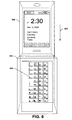
- Fig. 2 illustrates a front view 200 of a handheld device 202 (e.g., 102 in Fig. 1 ) having a protective shroud 204 (e.g., 104 in Fig. 1 ) partially formed there-around.
- a portion 206 of the front-face of the handheld device 202 is enclosed by the shroud 204, whereas a display portion 208 of the handheld device 202 remains substantially un-obscured by the shroud 204.
- the protective shroud 204 is configured to provide some protection against incidents (e.g ., drops, scratches, spills, etc.) that may damage the handheld device 202, while still allowing a user access to the display portion 208.
- Fig. 3 illustrates a back or rear view 300 of a handheld device 302 (e.g., 202 in Fig. 2 ), wherein the back-face of the device 302 is positioned on a substantially diametrically opposing side of the handheld device 302 from a display ( e.g ., 208 in Fig. 2 ).
- a protective shroud 304 e.g., 204 in Fig. 2
- encloses the back-face of the handheld device 302 e.g., the back-side or back-face of the handheld device 302 is covered up by the protective shroud 304).
- An input component (e.g ., 106 in Fig. 1 ), comprising an alphanumeric keypad 306 and a touch sensitive surface 308, is integral with the protective shroud 304. That is, the input component faces outward so that user input may be received while the protective shroud 304 is enclosing the handheld device 302. For example, if a user wants to type a text message on his/her cellular telephone, the user may rotate the phone 180° (e.g., so that backside of the phone is facing the user), type the message using the alphanumeric keypad 306, and rotate the phone back 180° to view the message on the display ( e.g ., 208 in Fig. 2 ).
- a speaker 310 and/or a microphone 312 may be integral with the protective shroud 304. These component may also be located on a portion of the protective shroud 304 positioned near the back-face 300 of a handheld device 302.
- a configuration similar to that illustrated in Fig. 4 is commonly found on cellular telephones that have full QWERTY keyboards.
- the input component 406 is sliding out of the protective shroud 404.
- the input component 406 may serve a purpose similar to that of a keyboard attached to a cellular telephone, but the input component 406 may be removable from the cellular telephone or other handheld device by detaching the protective sleeve 404 from the handheld device.
- Fig. 5 illustrates an input component 506 (e.g., 106 in Fig. 1 ) integral with a protective shroud 504 (e.g., 104 in Fig. 1 ).
- the input component is configured to rotate ( e.g ., counterclockwise) about a hinge 500 on the protective shroud 504 enclosing a handheld device 502.
- the input component 506 is configured to be latched to the protective shroud 504 ( e.g. nearer a back-face of the handheld device 502) when the input component 506 is not being used.
- the latch When a user desires to use the input component 506, the latch may be detached and the input component 506 may be rotated about the hinge 500 (e.g., counterclockwise) until the input component 506 is perpendicular to a side-face of the handheld device 502, for example. In this way, a user may view one or more keys comprised on the input component 506, for example, at the same time as he/she is viewing a display portion of the handheld device 502.
- Fig. 6 illustrates an input component 606 (e.g., 106 in Fig. 1 ) integral with a protective shroud 604 (e.g., 104 in Fig. 1 ).
- the input component 606 is positioned on an interior wall (e.g., a wall that makes physical contact with a handheld device) of the protective shroud 604.
- a handheld device 602 e.g., 102 in Fig. 1
- slides e.g ., downward 600
- the input component 606 may be covered by the back-face of the handheld device 602 when the handheld device 602 is enclosed in the protective shroud 604.
- Figs. 3-6 illustrates several example configurations for having an input component that is integral to a protective shroud.
- the input component may be integral to a plurality of different surfaces of the protective shroud, and the plurality of surfaces may be connected together through a series of hinges.
- the plurality of surfaces of the protective shroud may be configured to lay flat (e.g., forming a full sized keypad).
- an apparatus for receiving user input comprising: a selectively removable protective shroud configured to enclose at least a portion of a handheld device when attached to the handheld device; an input component integral with the protective shroud and configured to receive user input, the input component configured to generate an input signal based upon the received user input, wherein the input signal is transmitted to the handheld device; and a power source integral with the protective shroud and configured to supply power to the protective shroud.
- the apparatus comprises a wireless transceiver integral with the protective shroud and configured to transmit the input signal from the input component to the handheld device.
- the input component is configured to transmit the input signal to the handheld device through an electrically operable contact point operably coupling the handheld device to the input component.
- the input component is configured to selectively transmit data to a second device when not transmitting data to the handheld device.
- the second device does not comprise a handheld device.
- the word "exemplary” is used herein to mean serving as an example, instance, or illustration. Any aspect or design described herein as “exemplary” is not necessarily to be construed as advantageous over other aspects or designs. Rather, use of the word exemplary is intended to present concepts in a concrete fashion.
- the term “or” is intended to mean an inclusive “or” rather than an exclusive “or.” That is, unless specified otherwise, or clear from context, "X employs A or B” is intended to mean any of the natural inclusive permutations. That is, if X employs A; X employs B; or X employs both A and B, then "X employs A or B" is satisfied under any of the foregoing instances.
- the articles “a” and “an” as used in this application and the appended claims may generally be construed to mean “one or more” unless specified otherwise or clear from context to be directed to a singular form.
Landscapes
- Engineering & Computer Science (AREA)
- Signal Processing (AREA)
- Computer Networks & Wireless Communication (AREA)
- Theoretical Computer Science (AREA)
- Human Computer Interaction (AREA)
- Physics & Mathematics (AREA)
- Computer Hardware Design (AREA)
- General Engineering & Computer Science (AREA)
- General Physics & Mathematics (AREA)
- Mathematical Physics (AREA)
- Telephone Set Structure (AREA)
- Telephone Function (AREA)
Claims (13)
- Appareil (100, 200, 300, 400, 500, 600) pour un terminal de poche (102, 202, 302, 402, 502, 602), comprenant :un protecteur (104, 204, 304, 404, 504, 604) retirable de manière sélective et configuré pour renfermer au moins une partie du terminal de poche (102, 202, 302, 402, 502, 602) lorsqu'il est attaché au terminal de poche (102, 202, 302, 402, 502, 602);une source d'énergie (114) faisant partie intégrante du protecteur (104, 204, 304, 404, 504, 604) et configurée pour fournir de l'énergie au protecteur (104, 204, 304, 404, 504, 604); etun composant d'entrée (106, 206, 306, 406, 506, 606) faisant partie intégrante du protecteur (104, 204, 304, 404, 504, 604) et configuré pour recevoir une entrée d'utilisateur, le composant d'entrée (106, 206, 306, 406, 506, 606) étant configuré pour générer un signal d'entrée sur la base de l'entrée d'utilisateur, dans lequel le signal d'entrée est transmis au terminal de poche (102, 202, 302, 402, 502, 602), caractérisé en ce quele composant d'entrée (106, 206, 306, 406, 506, 606) est configuré pour transmettre de manière sélective des données à un second dispositif lorsqu'il ne transmet pas de données au terminal de poche (102, 202, 302, 402, 502, 602).
- Appareil (100, 200, 300, 400, 500, 600) selon la revendication 1, comprenant un émetteur-récepteur sans fil (108, 208, 308) faisant partie intégrante du protecteur (104, 204, 304, 404, 504, 604) et configuré pour faciliter une communication sans fil sélective avec le terminal de poche (102, 202, 302, 402, 502, 602), dans lequel le composant d'entrée (106, 206, 306, 406, 506, 606) est configuré pour transmettre l'entrée d'utilisateur reçue à l'émetteur-récepteur sans fil (108, 208, 308).
- Appareil (100, 200, 300, 400, 500, 600) selon la revendication 2, le composant d'entrée (106, 206, 306, 406, 506, 606) comprenant un clavier alphanumérique.
- Appareil (100, 200, 300, 400, 500, 600) selon la revendication 2, le composant d'entrée (106, 206, 306, 406, 506, 606) comprenant un ou plusieurs capteurs tactiles.
- Appareil (100, 200, 300, 400, 500, 600) selon la revendication 2, le composant d'entrée (106, 206, 306, 406, 506, 606) comprenant une ou plusieurs parties programmables par un utilisateur.
- Appareil (100, 200, 300, 400, 500, 600) selon la revendication 2, le composant d'entrée (106, 206, 306, 406, 506, 606) comprenant un contrôleur de jeux.
- Appareil (100, 200, 300, 400, 500, 600) selon l'une quelconque des revendications précédentes, dans lequel la source d'énergie (114) est une batterie faisant partie intégrante du protecteur (104, 204, 304, 404, 504,604).
- Appareil (100, 200, 300, 400, 500, 600) selon la revendication 7, la batterie étant configurée pour fournir de l'énergie au terminal de poche (102, 202, 302, 402, 502, 602) par le biais d'un point de contact utilisable électriquement et couplant de manière fonctionnelle la source d'énergie au terminal de poche (102, 202, 302, 402, 502, 602).
- Appareil (100, 200, 300, 400, 500, 600) selon l'une quelconque des revendications précédentes, dans lequel la source d'énergie (114) est une batterie faisant partie intégrante du terminal de poche (102, 202, 302, 402, 502, 602), l'énergie étant transmise par le biais d'un point de contact utilisable électriquement et couplant de manière fonctionnelle le terminal de poche (102, 202, 302, 402, 502, 602) à l'émetteur-récepteur sans fil (108, 208,308).
- Appareil (100, 200, 300, 400, 500, 600) selon l'une quelconque des revendications précédentes, comprenant un émetteur-récepteur sonore (110) faisant partie intégrante du protecteur (104, 204, 304, 404, 504, 604) et configuré pour réaliser au moins l'une parmi ce qui suit:l'émission d'ondes sonores sur la base de signaux d'émission reçus par l'émetteur-récepteur sonore (110) de l'émetteur-récepteur sans fil (108, 208, 308), dans lequel l'émetteur-récepteur sans fil (108, 208, 308) reçoit le signal d'émission du terminal de poche (102, 202, 302, 402, 502, 602), et la détection d'ondes sonores, l'émetteur-récepteur sonore (110) étant configuré pour transmettre des signaux de détection relatifs aux ondes sonores détectées à l'émetteur-récepteur sans fil (108, 208, 308), dans lequel l'émetteur-récepteur sans fil (108, 208, 308) transmet les signaux de détection au terminal de poche (102, 202, 302, 402, 502, 602).
- Appareil (100, 200, 300, 400, 500, 600) selon l'une quelconque des revendications précédentes, comprenant un dispositif de stockage (112) faisant partie intégrante du protecteur (104, 204, 304, 404, 504, 604) et configuré pour stocker des données relatives à une communication sans fil reçue par l'émetteur-récepteur sans fil (108, 208, 308).
- Appareil (100, 200, 300, 400, 500, 600) selon la revendication 1, comprenant un émetteur-récepteur sans fil (108, 208, 308) faisant partie intégrante du protecteur (104, 204, 304, 404, 504, 604) et configuré pour transmettre le signal d'entrée du composant d'entrée (106, 206, 306, 406, 506, 606) au terminal de poche (102, 202, 302, 402, 502, 602).
- Appareil (100, 200, 300, 400, 500, 600) selon la revendication 1, le second dispositif ne comprenant pas de terminal de poche (102, 202, 302, 402, 502, 602).
Applications Claiming Priority (2)
| Application Number | Priority Date | Filing Date | Title |
|---|---|---|---|
| US12/394,852 US8229509B2 (en) | 2009-02-27 | 2009-02-27 | Protective shroud for handheld device |
| PCT/US2010/023259 WO2010098962A2 (fr) | 2009-02-27 | 2010-02-05 | Protecteur pour terminal de poche |
Publications (3)
| Publication Number | Publication Date |
|---|---|
| EP2401855A2 EP2401855A2 (fr) | 2012-01-04 |
| EP2401855A4 EP2401855A4 (fr) | 2012-07-11 |
| EP2401855B1 true EP2401855B1 (fr) | 2014-12-24 |
Family
ID=42666143
Family Applications (1)
| Application Number | Title | Priority Date | Filing Date |
|---|---|---|---|
| EP10746620.3A Active EP2401855B1 (fr) | 2009-02-27 | 2010-02-05 | Protecteur pour terminal de poche |
Country Status (7)
| Country | Link |
|---|---|
| US (5) | US8229509B2 (fr) |
| EP (1) | EP2401855B1 (fr) |
| JP (2) | JP5613180B2 (fr) |
| KR (2) | KR101662344B1 (fr) |
| CN (2) | CN103220009A (fr) |
| CA (1) | CA2749676C (fr) |
| WO (1) | WO2010098962A2 (fr) |
Families Citing this family (68)
| Publication number | Priority date | Publication date | Assignee | Title |
|---|---|---|---|---|
| US8267787B2 (en) | 2009-01-16 | 2012-09-18 | Sony Computer Entertainment Inc. | Controller and portable electronic apparatus |
| US8229509B2 (en) | 2009-02-27 | 2012-07-24 | Microsoft Corporation | Protective shroud for handheld device |
| US8457601B2 (en) * | 2011-02-09 | 2013-06-04 | Certicall, Llc | Key responsive record, navigation and marking controls for communications system |
| US9201185B2 (en) | 2011-02-04 | 2015-12-01 | Microsoft Technology Licensing, Llc | Directional backlighting for display panels |
| US9052414B2 (en) | 2012-02-07 | 2015-06-09 | Microsoft Technology Licensing, Llc | Virtual image device |
| US9354748B2 (en) | 2012-02-13 | 2016-05-31 | Microsoft Technology Licensing, Llc | Optical stylus interaction |
| US8749529B2 (en) | 2012-03-01 | 2014-06-10 | Microsoft Corporation | Sensor-in-pixel display system with near infrared filter |
| US9360893B2 (en) | 2012-03-02 | 2016-06-07 | Microsoft Technology Licensing, Llc | Input device writing surface |
| US9064654B2 (en) | 2012-03-02 | 2015-06-23 | Microsoft Technology Licensing, Llc | Method of manufacturing an input device |
| US9134807B2 (en) | 2012-03-02 | 2015-09-15 | Microsoft Technology Licensing, Llc | Pressure sensitive key normalization |
| US8935774B2 (en) | 2012-03-02 | 2015-01-13 | Microsoft Corporation | Accessory device authentication |
| USRE48963E1 (en) | 2012-03-02 | 2022-03-08 | Microsoft Technology Licensing, Llc | Connection device for computing devices |
| US9870066B2 (en) | 2012-03-02 | 2018-01-16 | Microsoft Technology Licensing, Llc | Method of manufacturing an input device |
| US9075566B2 (en) | 2012-03-02 | 2015-07-07 | Microsoft Technoogy Licensing, LLC | Flexible hinge spine |
| US8873227B2 (en) | 2012-03-02 | 2014-10-28 | Microsoft Corporation | Flexible hinge support layer |
| US9426905B2 (en) | 2012-03-02 | 2016-08-23 | Microsoft Technology Licensing, Llc | Connection device for computing devices |
| US20130300590A1 (en) | 2012-05-14 | 2013-11-14 | Paul Henry Dietz | Audio Feedback |
| US10031556B2 (en) | 2012-06-08 | 2018-07-24 | Microsoft Technology Licensing, Llc | User experience adaptation |
| US8947353B2 (en) | 2012-06-12 | 2015-02-03 | Microsoft Corporation | Photosensor array gesture detection |
| US9019615B2 (en) | 2012-06-12 | 2015-04-28 | Microsoft Technology Licensing, Llc | Wide field-of-view virtual image projector |
| US9684382B2 (en) | 2012-06-13 | 2017-06-20 | Microsoft Technology Licensing, Llc | Input device configuration having capacitive and pressure sensors |
| US9459160B2 (en) | 2012-06-13 | 2016-10-04 | Microsoft Technology Licensing, Llc | Input device sensor configuration |
| US9073123B2 (en) | 2012-06-13 | 2015-07-07 | Microsoft Technology Licensing, Llc | Housing vents |
| US9256089B2 (en) | 2012-06-15 | 2016-02-09 | Microsoft Technology Licensing, Llc | Object-detecting backlight unit |
| US9355345B2 (en) | 2012-07-23 | 2016-05-31 | Microsoft Technology Licensing, Llc | Transparent tags with encoded data |
| US8964379B2 (en) | 2012-08-20 | 2015-02-24 | Microsoft Corporation | Switchable magnetic lock |
| US9152173B2 (en) | 2012-10-09 | 2015-10-06 | Microsoft Technology Licensing, Llc | Transparent display device |
| US8654030B1 (en) | 2012-10-16 | 2014-02-18 | Microsoft Corporation | Antenna placement |
| WO2014059624A1 (fr) | 2012-10-17 | 2014-04-24 | Microsoft Corporation | Protubérances de moulage par injection d'alliage métallique |
| WO2014059618A1 (fr) | 2012-10-17 | 2014-04-24 | Microsoft Corporation | Formation de graphique par ablation de matériau |
| EP2908971B1 (fr) | 2012-10-17 | 2018-01-03 | Microsoft Technology Licensing, LLC | Écoulements de moulage par injection d'alliage métallique |
| US8952892B2 (en) | 2012-11-01 | 2015-02-10 | Microsoft Corporation | Input location correction tables for input panels |
| US8786767B2 (en) | 2012-11-02 | 2014-07-22 | Microsoft Corporation | Rapid synchronized lighting and shuttering |
| US9513748B2 (en) | 2012-12-13 | 2016-12-06 | Microsoft Technology Licensing, Llc | Combined display panel circuit |
| CN103057243B (zh) * | 2012-12-28 | 2015-04-15 | 厦门炜迪电子科技有限公司 | 一体式太阳能充电键盘保护套的制作工艺及保护套 |
| HK1183407A2 (en) * | 2013-01-21 | 2013-12-20 | 3 P.M. Holding Limited | Accessory enclosure and input device |
| US9176538B2 (en) | 2013-02-05 | 2015-11-03 | Microsoft Technology Licensing, Llc | Input device configurations |
| US10578499B2 (en) | 2013-02-17 | 2020-03-03 | Microsoft Technology Licensing, Llc | Piezo-actuated virtual buttons for touch surfaces |
| US9638835B2 (en) | 2013-03-05 | 2017-05-02 | Microsoft Technology Licensing, Llc | Asymmetric aberration correcting lens |
| US9304549B2 (en) | 2013-03-28 | 2016-04-05 | Microsoft Technology Licensing, Llc | Hinge mechanism for rotatable component attachment |
| US9552777B2 (en) | 2013-05-10 | 2017-01-24 | Microsoft Technology Licensing, Llc | Phase control backlight |
| US9448631B2 (en) | 2013-12-31 | 2016-09-20 | Microsoft Technology Licensing, Llc | Input device haptics and pressure sensing |
| US9317072B2 (en) | 2014-01-28 | 2016-04-19 | Microsoft Technology Licensing, Llc | Hinge mechanism with preset positions |
| US9759854B2 (en) | 2014-02-17 | 2017-09-12 | Microsoft Technology Licensing, Llc | Input device outer layer and backlighting |
| US10120420B2 (en) | 2014-03-21 | 2018-11-06 | Microsoft Technology Licensing, Llc | Lockable display and techniques enabling use of lockable displays |
| US10324733B2 (en) | 2014-07-30 | 2019-06-18 | Microsoft Technology Licensing, Llc | Shutdown notifications |
| JP6235433B2 (ja) * | 2014-08-12 | 2017-11-22 | 東芝テック株式会社 | Icタグ読取装置 |
| US9424048B2 (en) | 2014-09-15 | 2016-08-23 | Microsoft Technology Licensing, Llc | Inductive peripheral retention device |
| US9447620B2 (en) | 2014-09-30 | 2016-09-20 | Microsoft Technology Licensing, Llc | Hinge mechanism with multiple preset positions |
| CN104869192B (zh) * | 2015-05-06 | 2018-10-26 | 京东方光科技有限公司 | 一种电子设备 |
| US10222889B2 (en) | 2015-06-03 | 2019-03-05 | Microsoft Technology Licensing, Llc | Force inputs and cursor control |
| US10416799B2 (en) | 2015-06-03 | 2019-09-17 | Microsoft Technology Licensing, Llc | Force sensing and inadvertent input control of an input device |
| US9752361B2 (en) | 2015-06-18 | 2017-09-05 | Microsoft Technology Licensing, Llc | Multistage hinge |
| US9864415B2 (en) | 2015-06-30 | 2018-01-09 | Microsoft Technology Licensing, Llc | Multistage friction hinge |
| US10061385B2 (en) | 2016-01-22 | 2018-08-28 | Microsoft Technology Licensing, Llc | Haptic feedback for a touch input device |
| US10344797B2 (en) | 2016-04-05 | 2019-07-09 | Microsoft Technology Licensing, Llc | Hinge with multiple preset positions |
| US10037057B2 (en) | 2016-09-22 | 2018-07-31 | Microsoft Technology Licensing, Llc | Friction hinge |
| EP3499336A1 (fr) * | 2017-12-13 | 2019-06-19 | Vestel Elektronik Sanayi ve Ticaret A.S. | Boîtier de téléphone interactif |
| CN111543761A (zh) * | 2020-06-05 | 2020-08-18 | 国家电网有限公司 | 一种电力电网大数据应用的掌上便携装置 |
| EP4430335A2 (fr) | 2021-11-12 | 2024-09-18 | reMarkable AS | Support de dispositif pour supporter un dispositif informatique |
| US12299218B2 (en) | 2023-06-11 | 2025-05-13 | Remarkable As | Active pen-stylus precise eraser |
| USD1092467S1 (en) | 2023-11-13 | 2025-09-09 | Remarkable As | Tablet computer |
| USD1106208S1 (en) | 2024-02-08 | 2025-12-16 | Remarkable As | Marker |
| USD1107023S1 (en) | 2024-02-08 | 2025-12-23 | Remarkable As | Marker |
| USD1115781S1 (en) | 2024-05-03 | 2026-03-03 | Remarkable As | Folio |
| CN121300639A (zh) | 2024-07-08 | 2026-01-09 | 瑞马科宝股份有限公司 | 可更换导电标记笔尖端 |
| CN121300641A (zh) | 2024-07-08 | 2026-01-09 | 瑞马科宝股份有限公司 | 标记笔保护系统 |
| CN121300642A (zh) | 2024-07-08 | 2026-01-09 | 瑞马科宝股份有限公司 | 标记笔书写系统 |
Family Cites Families (85)
| Publication number | Priority date | Publication date | Assignee | Title |
|---|---|---|---|---|
| DE3448618C2 (de) | 1984-11-23 | 1999-11-04 | Luk Lamellen & Kupplungsbau | Kupplungsscheibe mit Torsionsschwingungsdämpfer |
| JPH01130245A (ja) | 1987-11-16 | 1989-05-23 | Nec Corp | 周辺制御装置のトレース制御方式 |
| JPH01130245U (fr) * | 1988-02-29 | 1989-09-05 | ||
| JP3273994B2 (ja) * | 1993-04-14 | 2002-04-15 | セイコーエプソン株式会社 | キーボード装置および処理装置 |
| EP0852356A4 (fr) | 1996-06-20 | 1999-08-18 | Sega Enterprises Kk | Dispositif de jeu, unite peripherique et dispositif de relai |
| JPH11146049A (ja) | 1997-11-13 | 1999-05-28 | Shigeru Furuta | 携帯電話機操作装置 |
| US7358956B2 (en) | 1998-09-14 | 2008-04-15 | Microsoft Corporation | Method for providing feedback responsive to sensing a physical presence proximate to a control of an electronic device |
| JP3545961B2 (ja) | 1999-03-03 | 2004-07-21 | 株式会社オートネットワーク技術研究所 | 電話機ホルダー |
| US6488584B2 (en) | 1999-07-28 | 2002-12-03 | International Business Machines Corporation | Apparatus and method for providing keyboard input to a video game console |
| US6266241B1 (en) * | 1999-09-29 | 2001-07-24 | Hewlett-Packard Company | Notebook computer with ergonomic stand |
| US6477274B1 (en) | 1999-10-22 | 2002-11-05 | Ericsson Inc. | Handwritten character recognition devices and electronic devices incorporating same |
| JP4032581B2 (ja) | 1999-11-01 | 2008-01-16 | 株式会社デンソー | 車両用空調装置 |
| JP2001154990A (ja) * | 1999-11-25 | 2001-06-08 | Sharp Corp | クレードル |
| US6693626B1 (en) * | 1999-12-07 | 2004-02-17 | Immersion Corporation | Haptic feedback using a keyboard device |
| US6168331B1 (en) | 1999-12-16 | 2001-01-02 | Charles S. Vann | Case keyboard |
| EP1269298A2 (fr) * | 2000-03-30 | 2003-01-02 | Eleksen Limited | Appareil de saisie manuelle et processeur |
| KR100367054B1 (ko) | 2000-04-15 | 2003-01-09 | 인벤테크 베스타 컴퍼니 | 하드웨어에 기초한 순차 마스크롬 어댑터 |
| JP3949912B2 (ja) * | 2000-08-08 | 2007-07-25 | 株式会社エヌ・ティ・ティ・ドコモ | 携帯型電子機器、電子機器、振動発生器、振動による報知方法および報知制御方法 |
| DE10042946A1 (de) * | 2000-08-31 | 2002-03-14 | Siemens Ag | Schutzhülle |
| US7289083B1 (en) * | 2000-11-30 | 2007-10-30 | Palm, Inc. | Multi-sided display for portable computer |
| US6480377B2 (en) * | 2001-01-04 | 2002-11-12 | Fellowes Manufacturing Company | Protective case with a keyboard for a handheld computer |
| US6671170B2 (en) * | 2001-02-07 | 2003-12-30 | Palm, Inc. | Miniature keyboard for a hand held computer |
| US6456487B1 (en) * | 2001-04-30 | 2002-09-24 | Nokia Corporation | Enclosure for wireless communication device |
| JP2002366284A (ja) | 2001-06-08 | 2002-12-20 | Alps Electric Co Ltd | 携帯電子機器用キーボード装置及び充電装置 |
| US9544523B2 (en) | 2001-08-06 | 2017-01-10 | Ati Technologies Ulc | Wireless display apparatus and method |
| JP2003058278A (ja) | 2001-08-10 | 2003-02-28 | Alps Electric Co Ltd | 携帯電子機器用入力機能付きケース |
| US20030043037A1 (en) * | 2001-09-06 | 2003-03-06 | Lay Daniel Travis | System and method for preventing loss of an electrical device |
| US7663879B2 (en) * | 2001-11-19 | 2010-02-16 | Otter Products, Llc | Protective enclosure for personal digital assistant case having integrated back lighted keyboard |
| US20030100338A1 (en) * | 2001-11-28 | 2003-05-29 | Peter Lee | Personal digital assistant cover with an integrated keypad |
| US7002553B2 (en) * | 2001-12-27 | 2006-02-21 | Mark Shkolnikov | Active keyboard system for handheld electronic devices |
| GB2386346B (en) * | 2002-03-12 | 2005-06-15 | Eleksen Ltd | Flexible foldable keyboard |
| TW543493U (en) | 2002-04-01 | 2003-07-21 | Lite On Technology Corp | The game apparatus for a personal digital assistant |
| KR100460956B1 (ko) * | 2002-07-03 | 2004-12-09 | 삼성전자주식회사 | 휴대용 정보단말기의 키보드 |
| US6980777B2 (en) * | 2002-07-31 | 2005-12-27 | Nokia Corporation | Smart pouch cover for mobile device |
| EP1530866A4 (fr) | 2002-08-15 | 2009-09-16 | Khyber Technologies Corp | Dispositif portatif de saisie de donnees avec assistant personnel numerique amovible |
| WO2004038573A2 (fr) | 2002-10-20 | 2004-05-06 | Immersion Corporation | Systeme et procede fournissant une retroaction haptique rotative |
| US6999008B2 (en) | 2002-10-21 | 2006-02-14 | Actisys, Corporation | Universal mobile keyboard |
| JP2004180093A (ja) * | 2002-11-28 | 2004-06-24 | Funai Electric Co Ltd | 録画操作用リモコン |
| TW586658U (en) | 2003-01-13 | 2004-05-01 | Tatung Co | Hidden-type keyboard mechanism |
| CN1527569A (zh) | 2003-03-04 | 2004-09-08 | 阳庆电子股份有限公司 | 有线/无线的蓝芽键盘 |
| TW587794U (en) * | 2003-03-07 | 2004-05-11 | Tatung Co | Fastening structure of portable computer |
| CN2602549Y (zh) * | 2003-03-27 | 2004-02-04 | 华硕电脑股份有限公司 | 手持电子装置的护套 |
| US7203467B2 (en) * | 2003-04-14 | 2007-04-10 | Microsoft Corporation | Protective case for electronics in a mobile device |
| JP2004336140A (ja) | 2003-04-30 | 2004-11-25 | Toshiba Corp | スケジュール表示方法およびip電話端末 |
| US7106579B2 (en) * | 2003-06-09 | 2006-09-12 | Acer Inc. | Portable electronic device with a hinge mechanism |
| US6862171B1 (en) * | 2003-08-19 | 2005-03-01 | Acer Inc. | Portable electronic device with a sliding unit |
| JP4357892B2 (ja) | 2003-08-29 | 2009-11-04 | シャープ株式会社 | 携帯電話機器 |
| US20050125083A1 (en) * | 2003-11-10 | 2005-06-09 | Kiko Frederick J. | Automation apparatus and methods |
| US20060003709A1 (en) * | 2004-06-30 | 2006-01-05 | Nokia Corporation | Protective enclosure for a mobile terminal |
| WO2005082108A2 (fr) * | 2004-02-26 | 2005-09-09 | Rast Associates, Llc | Dispositif de clavier deployable comprenant des positions de touches deplaçables pour dispositifs electroniques portables |
| US7286860B2 (en) * | 2004-07-23 | 2007-10-23 | Dyna Llc | Systems and methods for a comfortable wireless communication device |
| US20060018089A1 (en) * | 2004-07-23 | 2006-01-26 | Chun-Chien Chou | Notebook type keyboard apparatus |
| JP2006301447A (ja) | 2005-04-22 | 2006-11-02 | Ricoh Co Ltd | 走査線曲がり測定装置及び光走査装置 |
| KR20070001529A (ko) | 2005-06-29 | 2007-01-04 | 주식회사 팬택 | 자성체를 이용하여 분리 가능한 커버를 가진 이동통신단말기 |
| US7327255B2 (en) * | 2005-07-07 | 2008-02-05 | Research In Motion Limited | Carrying case for a handheld device and methods thereof |
| FR2891928B1 (fr) | 2005-10-11 | 2008-12-19 | Abderrahim Ennadi | Clavier a ecran tactile universel multilingue et multifonction |
| US20070097014A1 (en) * | 2005-10-31 | 2007-05-03 | Solomon Mark C | Electronic device with flexible display screen |
| CN200983733Y (zh) * | 2006-01-20 | 2007-11-28 | 广州矽金塔电子有限公司 | 具有蓝牙传输功能的组合装置 |
| US20090009489A1 (en) | 2006-01-24 | 2009-01-08 | Yong-Jik Lee | Portable Apparatus and Method for Inputing Data With Electronic Pen and Transmitting Data |
| KR100826532B1 (ko) * | 2006-03-28 | 2008-05-02 | 엘지전자 주식회사 | 이동 통신 단말기 및 그의 키 입력 검출 방법 |
| JP2008022191A (ja) | 2006-07-12 | 2008-01-31 | Seiko Epson Corp | 携帯電話用キーボード |
| US7724204B2 (en) * | 2006-10-02 | 2010-05-25 | Pulse Engineering, Inc. | Connector antenna apparatus and methods |
| JP2008096620A (ja) | 2006-10-11 | 2008-04-24 | Ntt Electornics Corp | マイクロミラー、そのマイクロミラーを搭載するmems及びそのmemsの製造方法 |
| US8046039B2 (en) * | 2006-10-20 | 2011-10-25 | Lg Electronics Inc. | Mobile terminal and case for mobile terminal |
| GB0623629D0 (en) | 2006-11-27 | 2007-01-03 | Addonit Ltd | Accessories for hand-held electronic devices |
| KR100885699B1 (ko) | 2006-12-01 | 2009-02-26 | 엘지전자 주식회사 | 키 입력 장치 및 입력 방법 |
| US20080146206A1 (en) * | 2006-12-13 | 2008-06-19 | Pichardo Luis A | Method and apparatus for routing content between mobile communication devices |
| EP2122900A4 (fr) * | 2007-01-22 | 2014-07-23 | Spyrus Inc | Dispositif de chiffrement de données portable avec fonctionnalité de sécurité configurable et procédé de chiffrement de fichier |
| US7611113B2 (en) * | 2007-01-30 | 2009-11-03 | Inventec Corporation | Portable electronic device |
| US20080246731A1 (en) * | 2007-04-08 | 2008-10-09 | Michael Chechelniker | Backside Control Utility, BCU. |
| CN101731001A (zh) | 2007-06-04 | 2010-06-09 | 桑迪士克以色列有限公司 | 协同串联式口袋装置 |
| US20090027346A1 (en) | 2007-07-16 | 2009-01-29 | Srivastava Aditya Narain | Methods and systems for personalizing and branding mobile device keypads |
| CN201114710Y (zh) * | 2007-08-07 | 2008-09-10 | 李明 | 新型蓝牙耳机 |
| US20090120980A1 (en) | 2007-11-09 | 2009-05-14 | Mitchell Vicera Calayo | Accessory Case for Handheld Electronic Device |
| KR101474418B1 (ko) * | 2007-11-09 | 2014-12-19 | 엘지전자 주식회사 | 파우치 및 그를 구비한 휴대 단말기 |
| CN201185725Y (zh) * | 2008-03-13 | 2009-01-28 | 傅家诚 | 影音播放器的保护套装置 |
| JP2009267490A (ja) | 2008-04-22 | 2009-11-12 | Softbank Mobile Corp | 拡張機器 |
| US20100039388A1 (en) * | 2008-08-13 | 2010-02-18 | Allen Ku | Keyboard apparatus integrated with touch input module |
| US8730669B2 (en) * | 2008-08-15 | 2014-05-20 | Lenovo (Singapore) Pte. Ltd. | Transformer case for notebook slate computer with wireless keyboard |
| US20100079379A1 (en) * | 2008-09-26 | 2010-04-01 | Sony Ericsson Mobile Communications Ab | Portable communication device having an electroluminescent driven haptic keypad |
| US7612997B1 (en) * | 2008-11-17 | 2009-11-03 | Incase Designs Corp. | Portable electronic device case with battery |
| US8229509B2 (en) | 2009-02-27 | 2012-07-24 | Microsoft Corporation | Protective shroud for handheld device |
| CN102098888A (zh) * | 2009-12-15 | 2011-06-15 | 鸿富锦精密工业(深圳)有限公司 | 便携式电子装置 |
| JP5428967B2 (ja) | 2010-03-15 | 2014-02-26 | 富士ゼロックス株式会社 | 文書処理システム及び文書処理プログラム |
| US8522965B1 (en) | 2012-12-24 | 2013-09-03 | Chih-Hao Hsiung | Supportive protective cover for a handheld device |
-
2009
- 2009-02-27 US US12/394,852 patent/US8229509B2/en active Active
-
2010
- 2010-02-05 KR KR1020117019778A patent/KR101662344B1/ko active Active
- 2010-02-05 KR KR1020167026503A patent/KR101789001B1/ko active Active
- 2010-02-05 CA CA2749676A patent/CA2749676C/fr active Active
- 2010-02-05 EP EP10746620.3A patent/EP2401855B1/fr active Active
- 2010-02-05 CN CN2013100037124A patent/CN103220009A/zh active Pending
- 2010-02-05 CN CN2010800097331A patent/CN102334327A/zh active Pending
- 2010-02-05 JP JP2011552061A patent/JP5613180B2/ja active Active
- 2010-02-05 WO PCT/US2010/023259 patent/WO2010098962A2/fr not_active Ceased
-
2012
- 2012-07-02 US US13/540,558 patent/US9621214B2/en active Active
-
2014
- 2014-09-05 JP JP2014180974A patent/JP5989726B2/ja active Active
-
2015
- 2015-12-30 US US14/984,887 patent/US9954993B2/en active Active
-
2017
- 2017-03-29 US US15/473,445 patent/US20170207809A1/en not_active Abandoned
- 2017-04-14 US US15/488,289 patent/US20170223165A1/en not_active Abandoned
Also Published As
| Publication number | Publication date |
|---|---|
| EP2401855A2 (fr) | 2012-01-04 |
| JP2012519418A (ja) | 2012-08-23 |
| JP5613180B2 (ja) | 2014-10-22 |
| JP2015008525A (ja) | 2015-01-15 |
| EP2401855A4 (fr) | 2012-07-11 |
| US9621214B2 (en) | 2017-04-11 |
| US20170223165A1 (en) | 2017-08-03 |
| US9954993B2 (en) | 2018-04-24 |
| CA2749676C (fr) | 2017-12-19 |
| US20170207809A1 (en) | 2017-07-20 |
| CN102334327A (zh) | 2012-01-25 |
| WO2010098962A3 (fr) | 2011-03-31 |
| CN103220009A (zh) | 2013-07-24 |
| US20100222109A1 (en) | 2010-09-02 |
| JP5989726B2 (ja) | 2016-09-07 |
| KR20160117625A (ko) | 2016-10-10 |
| KR101789001B1 (ko) | 2017-10-20 |
| CA2749676A1 (fr) | 2010-09-02 |
| US20160191100A1 (en) | 2016-06-30 |
| KR20110120911A (ko) | 2011-11-04 |
| KR101662344B1 (ko) | 2016-10-04 |
| US20120270607A1 (en) | 2012-10-25 |
| WO2010098962A2 (fr) | 2010-09-02 |
| US8229509B2 (en) | 2012-07-24 |
Similar Documents
| Publication | Publication Date | Title |
|---|---|---|
| EP2401855B1 (fr) | Protecteur pour terminal de poche | |
| US8050716B2 (en) | Mobile terminal | |
| US8170633B2 (en) | Mobile terminal configured to be mounted on a user's wrist or forearm | |
| US8279174B2 (en) | Display device and method of controlling the display device | |
| US8619004B2 (en) | Mobile terminal using touch screen and method of controlling the same | |
| KR101488796B1 (ko) | 휴대 단말기 및 그 제어방법 | |
| US20070176902A1 (en) | Providing input data | |
| KR20140092722A (ko) | 정보를 디스플레이하는 모바일 장치 및 방법 | |
| CN101371216A (zh) | 无线手持装置和gui控制方法 | |
| US20040189609A1 (en) | Optical pointing device and method therefor | |
| KR101387507B1 (ko) | 이동통신 단말기 및 이를 이용한 서브 메뉴 구현방법 | |
| KR101348357B1 (ko) | 휴대 단말기 및 그 동작방법 | |
| KR20100125804A (ko) | 이동 단말기 및 그 제어 방법 | |
| US8692694B2 (en) | Method to detect and recover from stuck keys on an electronic device keyboard | |
| KR20100034592A (ko) | 휴대 단말기 및 그 동작방법 | |
| KR101608650B1 (ko) | 휴대 단말기 및 그 제어방법 | |
| KR101506489B1 (ko) | 가속도 센서를 이용하여 동작 제어가 가능한 휴대 단말기및 그 제어방법 | |
| CA2707896A1 (fr) | Methode de detection et de retablissement de touches bloquees de clavier de dispositif electronique | |
| KR20110013766A (ko) | 휴대 단말기 및 그 동작제어 방법 | |
| KR20100117381A (ko) | 터치 센서를 구비하는 휴대 단말기 및 그 동작방법 | |
| KR20120010522A (ko) | 휴대 전자기기 |
Legal Events
| Date | Code | Title | Description |
|---|---|---|---|
| PUAI | Public reference made under article 153(3) epc to a published international application that has entered the european phase |
Free format text: ORIGINAL CODE: 0009012 |
|
| 17P | Request for examination filed |
Effective date: 20110822 |
|
| AK | Designated contracting states |
Kind code of ref document: A2 Designated state(s): AT BE BG CH CY CZ DE DK EE ES FI FR GB GR HR HU IE IS IT LI LT LU LV MC MK MT NL NO PL PT RO SE SI SK SM TR |
|
| DAX | Request for extension of the european patent (deleted) | ||
| A4 | Supplementary search report drawn up and despatched |
Effective date: 20120613 |
|
| RIC1 | Information provided on ipc code assigned before grant |
Ipc: H04B 1/38 20060101AFI20120606BHEP |
|
| REG | Reference to a national code |
Ref country code: DE Ref legal event code: R079 Ref document number: 602010021265 Country of ref document: DE Free format text: PREVIOUS MAIN CLASS: H04M0001020000 Ipc: H04B0001380000 |
|
| GRAP | Despatch of communication of intention to grant a patent |
Free format text: ORIGINAL CODE: EPIDOSNIGR1 |
|
| RIC1 | Information provided on ipc code assigned before grant |
Ipc: H04B 1/38 20060101AFI20140710BHEP |
|
| INTG | Intention to grant announced |
Effective date: 20140805 |
|
| RAP1 | Party data changed (applicant data changed or rights of an application transferred) |
Owner name: MICROSOFT CORPORATION |
|
| GRAS | Grant fee paid |
Free format text: ORIGINAL CODE: EPIDOSNIGR3 |
|
| GRAA | (expected) grant |
Free format text: ORIGINAL CODE: 0009210 |
|
| AK | Designated contracting states |
Kind code of ref document: B1 Designated state(s): AT BE BG CH CY CZ DE DK EE ES FI FR GB GR HR HU IE IS IT LI LT LU LV MC MK MT NL NO PL PT RO SE SI SK SM TR |
|
| REG | Reference to a national code |
Ref country code: GB Ref legal event code: FG4D |
|
| REG | Reference to a national code |
Ref country code: CH Ref legal event code: EP |
|
| REG | Reference to a national code |
Ref country code: IE Ref legal event code: FG4D |
|
| REG | Reference to a national code |
Ref country code: AT Ref legal event code: REF Ref document number: 703582 Country of ref document: AT Kind code of ref document: T Effective date: 20150115 |
|
| REG | Reference to a national code |
Ref country code: DE Ref legal event code: R096 Ref document number: 602010021265 Country of ref document: DE Effective date: 20150219 |
|
| REG | Reference to a national code |
Ref country code: NL Ref legal event code: T3 |
|
| REG | Reference to a national code |
Ref country code: CH Ref legal event code: PUE Owner name: MICROSOFT TECHNOLOGY LICENSING, LLC, US Free format text: FORMER OWNER: MICROSOFT CORPORATION, US |
|
| RAP2 | Party data changed (patent owner data changed or rights of a patent transferred) |
Owner name: MICROSOFT TECHNOLOGY LICENSING, LLC |
|
| PG25 | Lapsed in a contracting state [announced via postgrant information from national office to epo] |
Ref country code: FI Free format text: LAPSE BECAUSE OF FAILURE TO SUBMIT A TRANSLATION OF THE DESCRIPTION OR TO PAY THE FEE WITHIN THE PRESCRIBED TIME-LIMIT Effective date: 20141224 Ref country code: NO Free format text: LAPSE BECAUSE OF FAILURE TO SUBMIT A TRANSLATION OF THE DESCRIPTION OR TO PAY THE FEE WITHIN THE PRESCRIBED TIME-LIMIT Effective date: 20150324 Ref country code: LT Free format text: LAPSE BECAUSE OF FAILURE TO SUBMIT A TRANSLATION OF THE DESCRIPTION OR TO PAY THE FEE WITHIN THE PRESCRIBED TIME-LIMIT Effective date: 20141224 |
|
| REG | Reference to a national code |
Ref country code: LT Ref legal event code: MG4D |
|
| PG25 | Lapsed in a contracting state [announced via postgrant information from national office to epo] |
Ref country code: SE Free format text: LAPSE BECAUSE OF FAILURE TO SUBMIT A TRANSLATION OF THE DESCRIPTION OR TO PAY THE FEE WITHIN THE PRESCRIBED TIME-LIMIT Effective date: 20141224 Ref country code: LV Free format text: LAPSE BECAUSE OF FAILURE TO SUBMIT A TRANSLATION OF THE DESCRIPTION OR TO PAY THE FEE WITHIN THE PRESCRIBED TIME-LIMIT Effective date: 20141224 Ref country code: GR Free format text: LAPSE BECAUSE OF FAILURE TO SUBMIT A TRANSLATION OF THE DESCRIPTION OR TO PAY THE FEE WITHIN THE PRESCRIBED TIME-LIMIT Effective date: 20150325 Ref country code: HR Free format text: LAPSE BECAUSE OF FAILURE TO SUBMIT A TRANSLATION OF THE DESCRIPTION OR TO PAY THE FEE WITHIN THE PRESCRIBED TIME-LIMIT Effective date: 20141224 |
|
| REG | Reference to a national code |
Ref country code: AT Ref legal event code: MK05 Ref document number: 703582 Country of ref document: AT Kind code of ref document: T Effective date: 20141224 |
|
| PG25 | Lapsed in a contracting state [announced via postgrant information from national office to epo] |
Ref country code: SK Free format text: LAPSE BECAUSE OF FAILURE TO SUBMIT A TRANSLATION OF THE DESCRIPTION OR TO PAY THE FEE WITHIN THE PRESCRIBED TIME-LIMIT Effective date: 20141224 Ref country code: ES Free format text: LAPSE BECAUSE OF FAILURE TO SUBMIT A TRANSLATION OF THE DESCRIPTION OR TO PAY THE FEE WITHIN THE PRESCRIBED TIME-LIMIT Effective date: 20141224 Ref country code: CZ Free format text: LAPSE BECAUSE OF FAILURE TO SUBMIT A TRANSLATION OF THE DESCRIPTION OR TO PAY THE FEE WITHIN THE PRESCRIBED TIME-LIMIT Effective date: 20141224 Ref country code: EE Free format text: LAPSE BECAUSE OF FAILURE TO SUBMIT A TRANSLATION OF THE DESCRIPTION OR TO PAY THE FEE WITHIN THE PRESCRIBED TIME-LIMIT Effective date: 20141224 Ref country code: RO Free format text: LAPSE BECAUSE OF FAILURE TO SUBMIT A TRANSLATION OF THE DESCRIPTION OR TO PAY THE FEE WITHIN THE PRESCRIBED TIME-LIMIT Effective date: 20141224 |
|
| PG25 | Lapsed in a contracting state [announced via postgrant information from national office to epo] |
Ref country code: PL Free format text: LAPSE BECAUSE OF FAILURE TO SUBMIT A TRANSLATION OF THE DESCRIPTION OR TO PAY THE FEE WITHIN THE PRESCRIBED TIME-LIMIT Effective date: 20141224 Ref country code: IS Free format text: LAPSE BECAUSE OF FAILURE TO SUBMIT A TRANSLATION OF THE DESCRIPTION OR TO PAY THE FEE WITHIN THE PRESCRIBED TIME-LIMIT Effective date: 20150424 Ref country code: AT Free format text: LAPSE BECAUSE OF FAILURE TO SUBMIT A TRANSLATION OF THE DESCRIPTION OR TO PAY THE FEE WITHIN THE PRESCRIBED TIME-LIMIT Effective date: 20141224 |
|
| REG | Reference to a national code |
Ref country code: DE Ref legal event code: R097 Ref document number: 602010021265 Country of ref document: DE |
|
| PG25 | Lapsed in a contracting state [announced via postgrant information from national office to epo] |
Ref country code: LU Free format text: LAPSE BECAUSE OF FAILURE TO SUBMIT A TRANSLATION OF THE DESCRIPTION OR TO PAY THE FEE WITHIN THE PRESCRIBED TIME-LIMIT Effective date: 20150205 |
|
| REG | Reference to a national code |
Ref country code: CH Ref legal event code: PL |
|
| PG25 | Lapsed in a contracting state [announced via postgrant information from national office to epo] |
Ref country code: MC Free format text: LAPSE BECAUSE OF FAILURE TO SUBMIT A TRANSLATION OF THE DESCRIPTION OR TO PAY THE FEE WITHIN THE PRESCRIBED TIME-LIMIT Effective date: 20141224 Ref country code: DK Free format text: LAPSE BECAUSE OF FAILURE TO SUBMIT A TRANSLATION OF THE DESCRIPTION OR TO PAY THE FEE WITHIN THE PRESCRIBED TIME-LIMIT Effective date: 20141224 Ref country code: LI Free format text: LAPSE BECAUSE OF NON-PAYMENT OF DUE FEES Effective date: 20150228 Ref country code: CH Free format text: LAPSE BECAUSE OF NON-PAYMENT OF DUE FEES Effective date: 20150228 |
|
| PLBE | No opposition filed within time limit |
Free format text: ORIGINAL CODE: 0009261 |
|
| STAA | Information on the status of an ep patent application or granted ep patent |
Free format text: STATUS: NO OPPOSITION FILED WITHIN TIME LIMIT |
|
| REG | Reference to a national code |
Ref country code: IE Ref legal event code: MM4A |
|
| 26N | No opposition filed |
Effective date: 20150925 |
|
| PG25 | Lapsed in a contracting state [announced via postgrant information from national office to epo] |
Ref country code: IT Free format text: LAPSE BECAUSE OF FAILURE TO SUBMIT A TRANSLATION OF THE DESCRIPTION OR TO PAY THE FEE WITHIN THE PRESCRIBED TIME-LIMIT Effective date: 20141224 |
|
| REG | Reference to a national code |
Ref country code: FR Ref legal event code: PLFP Year of fee payment: 7 |
|
| PG25 | Lapsed in a contracting state [announced via postgrant information from national office to epo] |
Ref country code: IE Free format text: LAPSE BECAUSE OF NON-PAYMENT OF DUE FEES Effective date: 20150205 |
|
| PG25 | Lapsed in a contracting state [announced via postgrant information from national office to epo] |
Ref country code: SI Free format text: LAPSE BECAUSE OF FAILURE TO SUBMIT A TRANSLATION OF THE DESCRIPTION OR TO PAY THE FEE WITHIN THE PRESCRIBED TIME-LIMIT Effective date: 20141224 |
|
| PG25 | Lapsed in a contracting state [announced via postgrant information from national office to epo] |
Ref country code: BE Free format text: LAPSE BECAUSE OF FAILURE TO SUBMIT A TRANSLATION OF THE DESCRIPTION OR TO PAY THE FEE WITHIN THE PRESCRIBED TIME-LIMIT Effective date: 20141224 |
|
| PG25 | Lapsed in a contracting state [announced via postgrant information from national office to epo] |
Ref country code: MT Free format text: LAPSE BECAUSE OF FAILURE TO SUBMIT A TRANSLATION OF THE DESCRIPTION OR TO PAY THE FEE WITHIN THE PRESCRIBED TIME-LIMIT Effective date: 20141224 |
|
| REG | Reference to a national code |
Ref country code: FR Ref legal event code: PLFP Year of fee payment: 8 |
|
| PG25 | Lapsed in a contracting state [announced via postgrant information from national office to epo] |
Ref country code: BG Free format text: LAPSE BECAUSE OF FAILURE TO SUBMIT A TRANSLATION OF THE DESCRIPTION OR TO PAY THE FEE WITHIN THE PRESCRIBED TIME-LIMIT Effective date: 20141224 Ref country code: HU Free format text: LAPSE BECAUSE OF FAILURE TO SUBMIT A TRANSLATION OF THE DESCRIPTION OR TO PAY THE FEE WITHIN THE PRESCRIBED TIME-LIMIT; INVALID AB INITIO Effective date: 20100205 Ref country code: SM Free format text: LAPSE BECAUSE OF FAILURE TO SUBMIT A TRANSLATION OF THE DESCRIPTION OR TO PAY THE FEE WITHIN THE PRESCRIBED TIME-LIMIT Effective date: 20141224 |
|
| PG25 | Lapsed in a contracting state [announced via postgrant information from national office to epo] |
Ref country code: CY Free format text: LAPSE BECAUSE OF FAILURE TO SUBMIT A TRANSLATION OF THE DESCRIPTION OR TO PAY THE FEE WITHIN THE PRESCRIBED TIME-LIMIT Effective date: 20141224 |
|
| PG25 | Lapsed in a contracting state [announced via postgrant information from national office to epo] |
Ref country code: PT Free format text: LAPSE BECAUSE OF FAILURE TO SUBMIT A TRANSLATION OF THE DESCRIPTION OR TO PAY THE FEE WITHIN THE PRESCRIBED TIME-LIMIT Effective date: 20150424 |
|
| PG25 | Lapsed in a contracting state [announced via postgrant information from national office to epo] |
Ref country code: TR Free format text: LAPSE BECAUSE OF FAILURE TO SUBMIT A TRANSLATION OF THE DESCRIPTION OR TO PAY THE FEE WITHIN THE PRESCRIBED TIME-LIMIT Effective date: 20141224 |
|
| REG | Reference to a national code |
Ref country code: NL Ref legal event code: PD Owner name: MICROSOFT TECHNOLOGY LICENSING, LLC; US Free format text: DETAILS ASSIGNMENT: CHANGE OF OWNER(S), ASSIGNMENT; FORMER OWNER NAME: MICROSOFT CORPORATION Effective date: 20170922 |
|
| REG | Reference to a national code |
Ref country code: GB Ref legal event code: 732E Free format text: REGISTERED BETWEEN 20171109 AND 20171115 |
|
| REG | Reference to a national code |
Ref country code: FR Ref legal event code: PLFP Year of fee payment: 9 |
|
| REG | Reference to a national code |
Ref country code: DE Ref legal event code: R082 Ref document number: 602010021265 Country of ref document: DE Representative=s name: OLSWANG GERMANY LLP, DE Ref country code: DE Ref legal event code: R081 Ref document number: 602010021265 Country of ref document: DE Owner name: MICROSOFT TECHNOLOGY LICENSING, LLC, REDMOND, US Free format text: FORMER OWNER: MICROSOFT CORPORATION, REDMOND, WASH., US |
|
| PG25 | Lapsed in a contracting state [announced via postgrant information from national office to epo] |
Ref country code: MK Free format text: LAPSE BECAUSE OF FAILURE TO SUBMIT A TRANSLATION OF THE DESCRIPTION OR TO PAY THE FEE WITHIN THE PRESCRIBED TIME-LIMIT Effective date: 20141224 |
|
| REG | Reference to a national code |
Ref country code: DE Ref legal event code: R082 Ref document number: 602010021265 Country of ref document: DE |
|
| P01 | Opt-out of the competence of the unified patent court (upc) registered |
Effective date: 20230501 |
|
| PGFP | Annual fee paid to national office [announced via postgrant information from national office to epo] |
Ref country code: NL Payment date: 20240123 Year of fee payment: 15 |
|
| PGFP | Annual fee paid to national office [announced via postgrant information from national office to epo] |
Ref country code: FR Payment date: 20240123 Year of fee payment: 15 |
|
| REG | Reference to a national code |
Ref country code: NL Ref legal event code: MM Effective date: 20250301 |
|
| PG25 | Lapsed in a contracting state [announced via postgrant information from national office to epo] |
Ref country code: NL Free format text: LAPSE BECAUSE OF NON-PAYMENT OF DUE FEES Effective date: 20250301 |
|
| PG25 | Lapsed in a contracting state [announced via postgrant information from national office to epo] |
Ref country code: FR Free format text: LAPSE BECAUSE OF NON-PAYMENT OF DUE FEES Effective date: 20250228 |
|
| PGFP | Annual fee paid to national office [announced via postgrant information from national office to epo] |
Ref country code: GB Payment date: 20260121 Year of fee payment: 17 |
|
| PGFP | Annual fee paid to national office [announced via postgrant information from national office to epo] |
Ref country code: DE Payment date: 20260121 Year of fee payment: 17 |