EP2401860B1 - Appareil d'imagerie, appareil d'affichage d'image, procédé d'imagerie, procédé d'affichage d'image et procédé de correction de position de cadre de zone de mise au point - Google Patents
Appareil d'imagerie, appareil d'affichage d'image, procédé d'imagerie, procédé d'affichage d'image et procédé de correction de position de cadre de zone de mise au point Download PDFInfo
- Publication number
- EP2401860B1 EP2401860B1 EP10746376.2A EP10746376A EP2401860B1 EP 2401860 B1 EP2401860 B1 EP 2401860B1 EP 10746376 A EP10746376 A EP 10746376A EP 2401860 B1 EP2401860 B1 EP 2401860B1
- Authority
- EP
- European Patent Office
- Prior art keywords
- focusing
- information
- focus
- imaging data
- distance
- Prior art date
- Legal status (The legal status is an assumption and is not a legal conclusion. Google has not performed a legal analysis and makes no representation as to the accuracy of the status listed.)
- Not-in-force
Links
Images



Classifications
-
- H—ELECTRICITY
- H04—ELECTRIC COMMUNICATION TECHNIQUE
- H04N—PICTORIAL COMMUNICATION, e.g. TELEVISION
- H04N23/00—Cameras or camera modules comprising electronic image sensors; Control thereof
- H04N23/60—Control of cameras or camera modules
- H04N23/67—Focus control based on electronic image sensor signals
- H04N23/675—Focus control based on electronic image sensor signals comprising setting of focusing regions
-
- G—PHYSICS
- G03—PHOTOGRAPHY; CINEMATOGRAPHY; ANALOGOUS TECHNIQUES USING WAVES OTHER THAN OPTICAL WAVES; ELECTROGRAPHY; HOLOGRAPHY
- G03B—APPARATUS OR ARRANGEMENTS FOR TAKING PHOTOGRAPHS OR FOR PROJECTING OR VIEWING THEM; APPARATUS OR ARRANGEMENTS EMPLOYING ANALOGOUS TECHNIQUES USING WAVES OTHER THAN OPTICAL WAVES; ACCESSORIES THEREFOR
- G03B13/00—Viewfinders; Focusing aids for cameras; Means for focusing for cameras; Autofocus systems for cameras
- G03B13/32—Means for focusing
- G03B13/34—Power focusing
- G03B13/36—Autofocus systems
-
- H—ELECTRICITY
- H04—ELECTRIC COMMUNICATION TECHNIQUE
- H04N—PICTORIAL COMMUNICATION, e.g. TELEVISION
- H04N23/00—Cameras or camera modules comprising electronic image sensors; Control thereof
- H04N23/60—Control of cameras or camera modules
- H04N23/63—Control of cameras or camera modules by using electronic viewfinders
- H04N23/633—Control of cameras or camera modules by using electronic viewfinders for displaying additional information relating to control or operation of the camera
- H04N23/635—Region indicators; Field of view indicators
-
- H—ELECTRICITY
- H04—ELECTRIC COMMUNICATION TECHNIQUE
- H04N—PICTORIAL COMMUNICATION, e.g. TELEVISION
- H04N5/00—Details of television systems
- H04N5/76—Television signal recording
- H04N5/765—Interface circuits between an apparatus for recording and another apparatus
- H04N5/77—Interface circuits between an apparatus for recording and another apparatus between a recording apparatus and a television camera
- H04N5/772—Interface circuits between an apparatus for recording and another apparatus between a recording apparatus and a television camera the recording apparatus and the television camera being placed in the same enclosure
-
- G—PHYSICS
- G02—OPTICS
- G02B—OPTICAL ELEMENTS, SYSTEMS OR APPARATUS
- G02B7/00—Mountings, adjusting means, or light-tight connections, for optical elements
- G02B7/28—Systems for automatic generation of focusing signals
- G02B7/36—Systems for automatic generation of focusing signals using image sharpness techniques, e.g. image processing techniques for generating autofocus signals
-
- H—ELECTRICITY
- H04—ELECTRIC COMMUNICATION TECHNIQUE
- H04N—PICTORIAL COMMUNICATION, e.g. TELEVISION
- H04N5/00—Details of television systems
- H04N5/76—Television signal recording
- H04N5/907—Television signal recording using static stores, e.g. storage tubes or semiconductor memories
-
- H—ELECTRICITY
- H04—ELECTRIC COMMUNICATION TECHNIQUE
- H04N—PICTORIAL COMMUNICATION, e.g. TELEVISION
- H04N9/00—Details of colour television systems
- H04N9/79—Processing of colour television signals in connection with recording
- H04N9/7921—Processing of colour television signals in connection with recording for more than one processing mode
-
- H—ELECTRICITY
- H04—ELECTRIC COMMUNICATION TECHNIQUE
- H04N—PICTORIAL COMMUNICATION, e.g. TELEVISION
- H04N9/00—Details of colour television systems
- H04N9/79—Processing of colour television signals in connection with recording
- H04N9/80—Transformation of the television signal for recording, e.g. modulation, frequency changing; Inverse transformation for playback
- H04N9/804—Transformation of the television signal for recording, e.g. modulation, frequency changing; Inverse transformation for playback involving pulse code modulation of the colour picture signal components
- H04N9/8042—Transformation of the television signal for recording, e.g. modulation, frequency changing; Inverse transformation for playback involving pulse code modulation of the colour picture signal components involving data reduction
- H04N9/8047—Transformation of the television signal for recording, e.g. modulation, frequency changing; Inverse transformation for playback involving pulse code modulation of the colour picture signal components involving data reduction using transform coding
-
- H—ELECTRICITY
- H04—ELECTRIC COMMUNICATION TECHNIQUE
- H04N—PICTORIAL COMMUNICATION, e.g. TELEVISION
- H04N9/00—Details of colour television systems
- H04N9/79—Processing of colour television signals in connection with recording
- H04N9/80—Transformation of the television signal for recording, e.g. modulation, frequency changing; Inverse transformation for playback
- H04N9/82—Transformation of the television signal for recording, e.g. modulation, frequency changing; Inverse transformation for playback the individual colour picture signal components being recorded simultaneously only
- H04N9/8205—Transformation of the television signal for recording, e.g. modulation, frequency changing; Inverse transformation for playback the individual colour picture signal components being recorded simultaneously only involving the multiplexing of an additional signal and the colour video signal
-
- H—ELECTRICITY
- H04—ELECTRIC COMMUNICATION TECHNIQUE
- H04N—PICTORIAL COMMUNICATION, e.g. TELEVISION
- H04N9/00—Details of colour television systems
- H04N9/79—Processing of colour television signals in connection with recording
- H04N9/80—Transformation of the television signal for recording, e.g. modulation, frequency changing; Inverse transformation for playback
- H04N9/82—Transformation of the television signal for recording, e.g. modulation, frequency changing; Inverse transformation for playback the individual colour picture signal components being recorded simultaneously only
- H04N9/8205—Transformation of the television signal for recording, e.g. modulation, frequency changing; Inverse transformation for playback the individual colour picture signal components being recorded simultaneously only involving the multiplexing of an additional signal and the colour video signal
- H04N9/8227—Transformation of the television signal for recording, e.g. modulation, frequency changing; Inverse transformation for playback the individual colour picture signal components being recorded simultaneously only involving the multiplexing of an additional signal and the colour video signal the additional signal being at least another television signal
Definitions
- the present invention relates to an imaging apparatus such as a digital camera, more specifically, to an imaging apparatus, an imaging method, an image display apparatus and a method of displaying an image. More particularly, the apparatuses and methods are configured to be capable of acquiring focused images which are required by a user, based on an amount of variation between each of all images shot continuously and a reference image, when the shot images are reproduced.
- focusing error focusing misalignment
- a method of using a focus-bracket shooting as a countermeasure of deviation or variation in focusing is known (for reference, see Japanese Patent Application Publication No. 7-318785 ).
- the inventors of the present application have proposed an imaging apparatus configured to divide a picture plane into small sections, perform a hill-climbing scan by a detection frame unit of each small section, decide an entire focal position by comparing a distribution of focal positions in each small section and predetermined threshold values, and decide the number of shootings by the focus-bracket shooting, as disclosed in EP-A-2 166 408 .
- a hill-climbing scan used in the existing focus bracket shooting there is generated a variation between a reproduced image and a display of focusing-area frames because data determining a focusing area and shot images are separate each other.
- EP 1 601 189 A2 discloses an autofocus system in which a target specified by an operator, while watching the video displayed on the screen, can be continuously put into focus.
- An aim of the present invention is to provide an imaging apparatus, an imaging method, an apparatus of displaying an image and a method of correcting a position of a focusing-area frame, in which before shooting, a reference image is acquired, a movement between the reference image ant each of shot images by a focus-bracket shooting is detected, a variation in a field angle is corrected by moving a coordinate of a focusing-area frame representing a focal position of the shot images based on the detected results, and the corrected focusing-area frame in which the field angle variation is corrected is displayed when the shot images are reproduced, and thereby, it is possible to accomplish ease of treatment in a case of selecting images obtained, for example, in a focus-bracket shooting according to the requirement of a user.
- an imaging apparatus that includes an optical unit capable of changing a focusing position and converting an image of a subject into an electric signal, an image processing device configured to convert the electric signal from the optical unit into imaging data and acquire a reference image before a shooting is taken, a display device configured to display the imaging data, a control device configured to control the image processing device, and a movement detecting device connected to the image processing device and the control device and configured to output movement information representing a variation between the imaging data and the reference image every each of the imaging data.
- the image processing device includes a correcting part configured to correct a focusing-area frame showing a focusing portion of the imaging data.
- the control device is configured to control the image processing device to display the corrected focusing-area frame on the display device when the imaging data are reproduced.
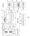
- FIG.1 illustrates an embodiment in which an imaging apparatus according to the present invention is applied to a digital camera.
- the digital camera 200 in the embodiment includes an optical unit 100 as a shooting optical system to form an image of a subject (not shown), a drive part 105 to drive the optical unit 100, an image processing device 110 to process the image formed by the optical unit 100, and a control device 120 to control the drive part 105, the optical unit 100 and the image processing device 110, as shown in FIG.1 .
- the control device 120 also acts to calculate various data from the optical unit 100, the image processing device 110 or the like.
- a program memory 121 and an operation part 122 which operates the control device 120 are connected to the control device 120.
- a distance-information acquiring device 111 and a display device 123 are connected to the image processing device 110.
- the display device 123 is configured to display images processed by the image processing device 110.
- the distance-information acquiring device 111 is referred to as a frequency-characteristic detection part which is described hereinafter.
- a movement-detecting device 112 a recording part or image buffer memory 126, a compression-extension processing part 124 and an image recording I/F part 125 are connected through a bus line 150 to the image processing device 110 and the control device 120.
- the optical unit 100 includes a lens 101, an aperture stop and shutter 102, an optical low-pass filter 103, and an image pickup device to receive an image of the subject, for example, a CMOS (complementary metal-oxide semiconductor) sensor 104 of a solid-state image sensing device.
- CMOS complementary metal-oxide semiconductor
- CMOS sensor 104 charge-coupled device
- the CMOS sensor 104 which is effective to a high readout is preferably used if the camera is used for continuous shooting.
- the CMOS sensor 104 includes a sensor portion 106, a driving portion 107, a CDS (correlation double sampling)-PGA (programmable gain amplifier) 108 and an ADC (analogue-digital converter) 109.
- CDS correlation double sampling
- PGA programmable gain amplifier
- ADC analogue-digital converter
- the lens 101 of the optical unit 100 is configured to change optically and mechanically a position thereof at times of focusing, zooming, actuating and stopping.
- the aperture-stop and shutter 102 is configured to perform a switching operation for an opening size of an aperture stop and simultaneously an opening and closing operation for a shutter, for an exposure of a still image.
- the drive part 105 performs the movement of the lens 101, the opening and closing operation of the aperture-stop and shutter 102, receiving drive instructions from the control device 120.
- the CMOS sensor 104 includes light receiving elements which are arranged in a two dimension and configured to convert an optical image imaged by the lens 101 into charges. The charges are output as an electrical signal to outside with a timing of a readout signal supplied from the driving portion 107.
- the signal output from the CMOS sensor 104 is image-processed in a predetermined format by the image processing device 110 disposed at a back of the optical unit, and the processed image is written and stored in a recording medium such as an SD card, compact flush card (registered trade mark), XD picture card, or the like, provided in the recording part 126, through the compression-extension processing part 124 and the image recording I/F part 125.
- the output from the CMOS sensor 104 is processed by the image processing device 110 in a predetermined form as an image for display, and the processed image is displayed on the display device 123 by updating optionally.
- the display device 123 is configured to perform a reproduction display and an OSD (On Screen Display) of images recorded in the recording medium.
- the image processing device 110 has some functions as mentioned above. More specifically, the image processing device 110 includes a focusing-position setting part configured to be settable a plurality of reference focusing positions for the optical unit, based on the distance information, a continuous shooting part configured to change sequentially focusing positions obtained by the optical unit to the reference focusing positions set by the focusing-position setting part and acquire a plurality of image data having different focusing distance by taking a plurality times of shootings continuously, a focusing-portion deciding part configured to decide a focusing portion in a screen of the imaging data based on the distance information acquired by the distance-information acquiring device, a reference-image acquiring part configured to acquire reference image data before the plurality of shootings are continuously taken by the continuous shooting part, and a focusing-frame displaying-position deciding part configured to acquire focusing-area frame-position information representing a display position of a focusing-area frame which shows a focused area of the imaging data, every the imaging data, based on the focusing portion and the movement information.
- the image processing device 110 includes a correcting part configured to correct the focusing-area frame based on the detected movement information,
- the control device 120 is configured to control the image processing device 110 to display the corrected focusing-area frame and the imaging data together on the display device 123 when the imaging data are reproduced.
- the recording part 126 is configured to record all the plurality of imaging data continuously shot by the continuous shooting part and the focusing-area frame-position information to correspond every each of the imaging data as one file.
- the distance-information acquiring device includes a distance-information imaging part configured to change sequentially the focusing positions of the optical unit to predetermined focusing positions more than the plurality of focusing positions and acquire a plurality of distance-information imaging data by taking a plurality of shootings continuously at their focusing positions, and a distance-information calculation part configured to calculate the distance information of the subject based on the plurality of distance-information imaging data acquired by the distance-information imaging part.
- the reference-image acquiring part is configured to acquire either of the plurality of distance-information imaging data acquired by the distance-information imaging part as the reference image data.
- the imaging data shot by the continuous shooting part are larger than that of the distance-information imaging data acquired by the distance-information imaging part in data size.
- the movement-detecting device 112 is configured to convert the plurality of imaging data acquired by the continuous shooting part into a size similar to that of the reference image data and output movement information corresponding thereto.
- the distance-information calculation part includes an area dividing part configured to divide the screen of the imaging data into a plurality of small areas, a frequency-component extracting part configured to extract a plurality of frequency components representing a focusing state of each of the small areas of the imaging data, and a small-area distance-information calculation part configured to calculate distance information of each of the small areas based on the frequency components extracted by the frequency-component extracting part.
- the frequency-component extracting part may be disposed in a back of the optical unit 100.
- the focusing-position setting part is configured to set a plurality of focusing positions of the optical unit based on the distance information every each of the small areas calculated by the small-area distance-information calculation part.
- the distance-information calculation part includes a focusing-position distribution-information acquiring part configured to acquire focusing-position distribution-information by calculating the number of small areas focused at their focusing positions based on the distance information every the small areas, calculated by the small-area distance-information calculation part.
- the focusing-position setting part is configured to set a plurality of focusing positions of the optical unit based on the focusing-position distribution-information.
- the imaging apparatus 200 further comprises a shooting-command receiving part configured to receive a shooting command,
- the continuous shooting part is configure to perform a plurality of shootings continuously based on the shooting command received by the shooting-command receiving part.
- the imaging apparatus 200 further comprises a focusing-command receiving part configured to receive a focusing command.
- the continuous shooting part is configured to perform a plurality of shootings continuously based on the focusing command received by the focusing-command receiving part.
- the distance-information acquiring device 111 is configured to acquire distance information formed in the frequency-component extracting part by a frequency detection of a hill-climbing scan, from the frequency-component extracting part disposed in a back of the optical unit.
- the distance-information acquiring device 111 is configure to acquire a plurality of reference image candidates with predetermined scan intervals and to store them, and decide reference images of the reference image candidates based on decided results of focusing positions for performing continuous shootings after completing a process of the hill-climbing scan.
- the image processing device 110 is configured to process image data while storing the image data in the recording part 126.
- the acquisition of the frequency characteristic (corresponding to a predetermined frequency component representing a focusing state in a space in a scan line) of the subject by the hill-climbing scan is performed in the distance-information acquiring device or the frequency-characteristic detection part 111.
- the distance-information acquiring device 111 is configured to acquire distance information by dividing the screen into small areas, detecting them with small area unit, and measuring a plurality of areas, as shown in FIG.2B which will be mentioned hereinafter.
- the distance-information acquiring device to acquire the distance information by measuring a distance may be structured by a ranging radar configured to acquire distance information of the subject.
- the calculation of focusing positions from the frequency characteristic or final decision of a plurality of focusing positions from the calculated results is performed by the control device 120.
- the movement-detecting device 112 is configured to detect a movement amount between two images supplied from the CMOS sensor 104 and output it. A detailed description of the movement-detecting device 112 is omitted, because it is usual. However, generally speaking, the movement-detecting device 112 can determine a direction of movement by quantifying concave and convex profiles of images and calculating an extreme value of a difference between two images while deviating x and y coordinates.
- the operation part 122 includes a two-step pressed release button configured to recognize and detect a state becoming OFF when releasing the release button in a half-pressed state (first release ON) where the release button is half pressed and a state becoming OFF when releasing the release button in a full-pressed state (second release ON) where the release button is fully pressed.
- FIG2A to FIG.2D are explanatory views for explaining a plurality of focusing positions in a focus-bracket shooting in the embodiment, FIG.2A subjects, FIG.2B detection frames, FIG.2C a state in which the subjects and the detection frames are overlapped, and FIG.2D a focusing-position distribution of each detection frame.
- the subjects shown in FIG.2A include two persons which have different distances and high-rise buildings which have infinite distances.
- the two persons and the high-rise buildings are important subjects. These subjects are shot at their focusing positions.
- the subjects and a focusing-area frame in which the focal positions of the subjects are aligned are displayed on a reproduced screen.
- the frequency-characteristic detection part 111 as shown in FIG.1 is structured in a form of detection frames.
- Each of the detection frames comprise one hundred and forty four (144) small areas formed by dividing a matrix-like shape of a field angle into twelve (12), as shown in FIG.2B .
- FIG.2C illustrates a state in which the subjects shown in FIG.2A and the detection frames shown in FIG.2B are overlapped. Focusing positions to the subjects in a state of small area units are calculated, and a function G (x) of a focusing-position distribution is formed by distributing the calculated focusing positions.
- Values, x0 to x15 plotted on a horizontal axis of a graph shown in FIG.2D show focusing positions obtained by a hill-climbing scan and a vertical axis of the graph shows the number of small areas focused at their focusing positions.
- a function F (x) is a predetermined threshold function
- the focusing-position distribution function G (x) is adapted to set positions at which the number (G (x)) of focused small areas larger than that of the threshold function F (x) as focusing positions in the focus-bracket shooting from scanned results and select the focusing positions from ones set.
- the threshold function, F (x) shown in FIG.2D has a characteristic in which two linear functions are combined as an example, as shown in the following formula.
- F x f x + ⁇
- the threshold function F (x) is an increasing function toward an infinity side, in other words, set to have a small value on a near distance. This is for the reason that a subject positioning a near distance is shot preferentially.
- FIG.2D a focus-bracket shooting is executed at five (5) points, x 4, x 5, x 6, x 11, and x 15, as an example.
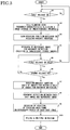
- FIG.3 is a flowchart showing a process including steps of performing a ranging by a hill-climbing scan, taking a focus-bracket shooting and storing shot images.
- a first release is turned on, that is to say, a half-pressed state of the two-step pressed release button is confirmed (S1), if the half-pressed state is detected (Yes in S1), then a hill-climbing scan is executed (S2).
- S1 a half-pressed state of the two-step pressed release button is confirmed (S1), if the half-pressed state is detected (Yes in S1), then a hill-climbing scan is executed (S2).
- frequency-characteristic detection part 111 frequency data at each scan position every the small areas dividing a screen are acquired.
- the two-step pressed release button is not in the half-pressed state at the initiation step (No in S1), a user waits that the two-step pressed release button is in the half-pressed state in step S1.
- All scanned images or images every predetermined scan intervals are acquired and stored in the recording part or image buffer memory 126 as reference-image candidates for movement detection, simultaneously with the acquisition of the frequency data at each scan position. Meanwhile, a capacity of the memory is reduced to a minimum resolution by a resize-process for consideration that a memory area is not occupied. As the capacity, a VGA size of about (vertical 480 pixels x horizontal 640 pixels) may be set because a movement amount of images on the entire screen is to be calculated in one direction, in the embodiment.
- a plurality of focusing positions is decided from the results of the hill-climbing scan (S3).
- various systems are considered.
- the five focusing positions x 4, x 5, x 6, x 11, and x 15, as shown in FIGs.2A to 2D may be decided.
- a reference image (or images) for movement detection which corresponds to a movement between the reference image and the shot image is decided from the results of the focusing positions (S4).
- the reference image is preferably set to an intermediate position between a near side end and a far side end of the focusing position decided in step S3.
- the reference-image candidate(s) stored at the time of the hill-climbing scan is deleted from the recording part 126 in a state leaving the decided images. More specifically, about the decision (S4) of the reference image, the focusing position x 9 which is a central position between the near side end x 4 and the far side end x 15, as shown in FIG.2D may be used.
- the focusing position x 5 is used for the reference image, if it is considered that a subject positioning at a near side is more important than a subject positioning at a far side when considering accuracy of variation between the focused position at the time of reproduction and the display frame, because it is often considered that a subject positioning at a near position is important in a shooting in a digital camera.
- the ON state of the first release in other words, the continuation of a shooting is confirmed again (S5). If the first release is not in ON state (No in S5), the process is returned to the initiation step. If the first release is in ON state (Yes in S5), the process is moved from the step 5 to the next step S6 confirming the full-pressed state of the two-step pressed release button.
- the process including the steps S1 to S5 is used for the decision of the reference image before shooting.
- the full-pressed state of the two-step pressed release button (second release) is confirmed (S6). If the full-pressed state is confirmed (Yes in S6), the focus-bracket shooting is executed depending on the decision made in step S3 (S7). At this time, it is noted that image data for recording and images for movement detection, which are reduced in a size similar to the reference image are prepared in the recording part 126 by the number of focus-bracket shootings.
- the movement detection is executed by the reference image decided before shooting and each of the reduced images shot by the focus-bracket shooting (S8).
- a movement amount between two screens of the reference images and each reduced image is output by inputting the reference image and each of the reduced images in the movement-detecting device 112. Therefore, if the number of the focus-bracket shootings is 5, the same five controls are repeated. Consequently, from this result, it is possible to know how much deviation of field angle of the recorded images shot by the focus-bracket shooting occurs from the reference image.
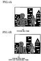
- FIGs.4A and 4B A concept of the correction is shown in FIGs.4A and 4B .
- FIG.4A it is determined that a frame 300 shown by a broken line on a front person is a focusing-area frame at the time of the hill-climbing scan.
- the frame 300 shown by the broken line corresponds to six frames of the detection frames (6, 4) to (11, 4) shown in FIG.2B , and corresponds to the focusing position x 5 as shown in FIG.2D .
- the focusing-area frame can be displayed properly onto the focusing position of each of the shot images.
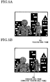
- FIGs.5A and 5B illustrate a focusing-area frame 500 which is disposed on a rear person and displayed on a different position from the focusing position x 5. It is determined in the hill-climbing scan that an area shown by a broken line onto the rear person is a focusing position or area.
- the frame 500 shown by the broken line corresponds to five frames of the detection frames (7, 9) to (11, 9) shown in FIG.2B and the focusing position x 11 shown in FIG.2D .
- the focusing-area frame 500 is corrected as a corrected focusing-area frame 600 as shown in FIG.5B based on the result of the movement-detecting device 112, similarly to the case shown in FIGs.4A and 4B .
- the information such as the corrected focusing-area frame and so on, acquired as mentioned above is stored in a recording medium or the like provided in the recording part 126 (S10).
- a filing is prepared by attaching the coordinate information representing the focusing-area frame, which is decided in the step S9 to the recorded image data.
- the plurality of image data shot by the focus-bracket shooting are stored as a multi-page file, in the embodiment.
- the multi-page file is prepared in the recording part 126.
- the multi-page file is explained in detail hereinafter.
- the plurality (n) of recorded images shot by changing focusing positions continuously, with the focus-bracket shooting are stored as one multi-page file formed by corresponding the recorded images to the information of the movement amount between the reference image decided before shooting and each of the recorded images.
- the recorded images are recorded in Exif (Exchangeable Image File Format) standardized by JEIDA (Japanese electronic industrial development association)
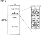
- the recorded images are written in tag information of a header part of Exif together with information such as a kind of a camera, date and time of shooting, a value of aperture, a shutter speed, a displayed position of the focusing-area frame and so on and stored in the Exif as recorded image data of the multi-page file.
- N (number) recorded image data are defined as a directory of a DCF (camera system standard) as shown in FIG.7 and n-recorded image data shot by the focus-bracket shooting are stored in one holder (continuous shooting 1 holder) together as a multi-page file, thereby a multi-page file, five multi-page files in the embodiment are prepared. Meanwhile, the multi-page file is stored in the recording medium such as the SD card or the like in the recording part 126, through the image recording I/F part 125 as shown in FIG.1 . The recorded images are extracted depending on information stored in the Exif.
- a multi-page file shown in FIG.8 differs from the multi-page file shown in FIG 7 in that n recorded images shot by the focus-bracket shooting are combined.
- the recorded image data for each multi-page file comprise recorded image-header portions and recorded image portions and are combined in order of shooting.
- Shooting condition data of the recorded images which are recorded image data of shooting such as pixel numbers, type of compression, date and time (including minute and second) of shooting, name of imaging apparatus for shooting the recorded images, exposure time, aperture value, sensitivity of shooting, focusing position, color space, and so on are included in each of the recorded-image header portions.
- a flag for discriminating the recorded images coordinate information relating to the reference image, information of frequency characteristic of detection frames, focusing positions, focusing-area frames, position information of the focusing-area frames, thumb nails of the recorded images and so on are included in each of the recorded image-header portions.
- the present invention makes it possible to provide a convenient imaging apparatus or digital camera capable of taking a focus-bracket shooting, avoiding a positional deviation of the focus-area frame displayed together with the shot images in reproduction of the shot images, accomplishing easy control by storing the shot images continuously shot by the focus-bracket shooting as a multi-page file, accomplishing easy treatment of image selection or the like desired by a user, moving a focus range wider than that of a conventional focus-bracket shooting, and adding the shot images to information of the focusing positions of a subject.
- the focus-bracket shooting is configured to take five images
- the focus-bracket shooting is configured to take about five to ten images in consideration of recent digital technology, it is possible to provide a convenient digital camera capable of responding to a request from a market and having less influence to usability due to a cost up of instruments and an increment of shooting time or recording-process time with an increment of buffer memory capacity.
- the image display apparatus in the example includes the display device 123 configured to display the recorded images or imaging data stored in recording medium provided in the recording part 126 of the aforementioned imaging apparatus.
- the imaging apparatus has a monitor function executed by the image display apparatus. Consequently, an exclusive reproduction device for displaying images is not needed.
- the focusing-area frame is displayed to be overlapped on the imaging data, based on the imaging data and the position information of the focusing-area frames corresponding to the imaging data.
- the image display apparatus includes a file-reading part configured to read a file recorded in the recording medium and the display device configured to display imaging data in the file read in the file-reading part.
- the file of the image data displayed on the display device includes a plurality of imaging data having different focusing distances, acquired by taking a plurality of continuous shootings and position information of focusing-area frames which is corresponded to the imaging data every each imaging datum and shows a display position to display a focusing-area frame representing a focusing portion of the imaging data.
- the selected one datum when one imaging datum is selected from the plurality of imaging data having different focusing distances, the selected one datum can be displayed on the display device in a state where the focusing-area frame based on focusing-area frame-position information corresponding to the one imaging datum is overlapped on the one imaging datum. Thereby, it is possible to select easily a focused image desired by a user, of the imaging data.
- the imaging data can be displayed on the display device to be switchable a continuous display mode for displaying the plurality of imaging data continuously and a tabulated mode or thumbnail display for displaying the plurality of imaging data together.
- the method of correcting a focusing-area frame comprises preparing an optical unit of forming images from a subject, acquiring distance information to the subject, detecting a movement amount between the images formed by the optical unit, forming a focusing-area frame for the images based on the distance information, displaying the images output from the optical unit and the focusing-area frame when reproducing the images, acquiring a reference image before shooting, and correcting the focusing-area frame by changing a displayed position of the focusing-area frame based on detected results of movement amount detected between the reference image and each of the images.
- a reference image before shooting is acquired, a movement-detection between the reference images and an image of images shot by a focus-bracket shooting is executed, a position of a focus-area frame is corrected based on the result of the movement-detection to correct deviation or variation of a field angle of the image, and the corrected focusing-area frame is displayed on the image, thereby a user can select a focused image easily.
Landscapes
- Engineering & Computer Science (AREA)
- Multimedia (AREA)
- Signal Processing (AREA)
- Physics & Mathematics (AREA)
- General Physics & Mathematics (AREA)
- Studio Devices (AREA)
- Automatic Focus Adjustment (AREA)
- Focusing (AREA)
- Details Of Cameras Including Film Mechanisms (AREA)
- Indication In Cameras, And Counting Of Exposures (AREA)
Claims (15)
- Appareil d'imagerie (200), comprenant :une unité optique (100) capable de changer une position de mise au point et de convertir une image d'un sujet en un signal électrique,un dispositif de traitement d'image (110) conçu pour convertir le signal électrique issu de l'unité optique en données d'imagerie et pour acquérir des données d'image de référence avant la réalisation d'un bracketing de mise au point, le dispositif de traitement d'image (110) comprenant une partie de réglage de position de mise au point conçue pour établir une pluralité de positions de mise au point de référence pour l'unité optique (100) pour le bracketing de mise au point et une partie de bracketing de mise au point conçue pour réaliser le bracketing de mise au point en fonction de la pluralité de positions de mise au point de référence établies,un dispositif d'affichage (123) conçu pour afficher les données d'imagerie,un dispositif de commande (120) conçu pour commander le dispositif de traitement d'image (110), etun dispositif de détection de mouvement (112) connecté au dispositif de traitement d'image (110) et au dispositif de commande (120) et conçu pour détecter, pour les données d'imagerie correspondant à chaque image prise lors du bracketing de mise au point, des informations de mouvement représentant une variation entre les données d'imagerie et les données d'image de référence ;le dispositif de traitement d'image (110) comprenant une partie de correction conçue pour corriger un cadre de zone de mise au point représentant une position de mise au point des données d'imagerie, en fonction des informations de mouvement détectées,le dispositif de commande (120) étant conçu pour commander le dispositif de traitement d'image (110) pour afficher conjointement le cadre de zone de mise au point corrigé et les données d'imagerie sur le dispositif d'affichage (123) lorsque les données d'imagerie sont reproduites.
- Appareil d'imagerie (200) selon la revendication 1, comprenant en outre une partie d'enregistrement (126) connectée au dispositif de traitement d'image (110) et conçue pour enregistrer les données d'imagerie, et un dispositif d'acquisition d'informations de distance (111) connecté au dispositif de traitement d'image (110) et conçu pour acquérir des informations de distance du sujet,
le dispositif d'affichage (123) étant conçu pour afficher les données d'imagerie enregistrées dans la partie d'enregistrement (126),
la partie de réglage de position de mise au point étant conçue pour établir la pluralité de positions de mise au point de référence pour l'unité optique (100), en fonction des informations de distance, la partie de bracketing de mise au point étant conçue pour faire passer de manière séquentielle les positions de mise au point obtenues par l'unité optique (100) aux positions de mise au point de référence établies par la partie de réglage de position de mise au point et pour acquérir une pluralité d'images présentant différentes distances focales prises une pluralité de fois lors du bracketing de mise au point,
le dispositif de traitement d'image (110) comprenant une partie de décision de secteur de mise au point conçue pour décider d'un secteur de mise au point dans un écran des données d'imagerie en fonction des informations de distance acquises par le dispositif d'acquisition d'informations de distance (111), une partie d'acquisition d'images de référence conçue pour acquérir des données d'image de référence avant que le bracketing de mise au point ne soit réalisé par la partie de bracketing de mise au point, et une partie de décision de position d'affichage de cadre de mise au point conçue pour acquérir des informations sur la position d'un cadre de zone de mise au point représentant une position d'affichage d'un cadre de zone de mise au point qui indique une zone mise au point des données d'imagerie, pour les données d'imagerie correspondant à chaque image prise lors du bracketing de mise au point, en fonction du secteur de mise au point et des informations de mouvement,
le dispositif d'affichage (123) étant conçu pour afficher le cadre de zone de mise au point superposé aux données d'imagerie, en fonction des données d'imagerie enregistrées dans la partie d'enregistrement (126) et des informations sur la position du cadre de zone de mise au point correspondant aux données d'imagerie. - Appareil d'imagerie (200) selon la revendication 1, comprenant en outre une partie d'enregistrement (126) connectée au dispositif de traitement d'image (110) et conçue pour enregistrer les données d'imagerie, et un dispositif d'acquisition d'informations de distance (111) connecté au dispositif de traitement d'image (110) et conçu pour acquérir des informations de distance du sujet,
le dispositif d'affichage (123) étant conçu pour afficher les données d'imagerie enregistrées dans la partie d'enregistrement (126),
la partie de réglage de position de mise au point étant conçue pour établir la pluralité de positions de mise au point de référence pour l'unité optique (100), en fonction des informations de distance, la partie de bracketing de mise au point étant conçue pour faire passer de manière séquentielle les positions de mise au point obtenues par l'unité optique aux positions de mise au point de référence établies par la partie de réglage de position de mise au point, et pour acquérir une pluralité d'images présentant différentes distances focales prises une pluralité de fois lors du bracketing de mise au point,
le dispositif de traitement d'image (110) comprenant une partie de décision de secteur de mise au point conçue pour décider d'un secteur de mise au point dans un écran des données d'imagerie en fonction des informations de distance acquises par le dispositif d'acquisition d'informations de distance (111), une partie d'acquisition d'images de référence conçue pour acquérir des données d'image de référence avant que le bracketing de mise au point ne soit réalisé par la partie de bracketing de mise au point, et une partie de décision de position d'affichage de cadre de mise au point conçue pour acquérir des informations sur la position du cadre de zone de mise au point représentant une position d'affichage d'un cadre de zone de mise au point qui indique une zone mise au point des données d'imagerie, pour les données d'imagerie correspondant à chaque image prise lors du bracketing de mise au point, en fonction du secteur de mise au point et des informations de mouvement,
la partie d'enregistrement (126) étant conçue pour enregistrer les données d'imagerie de toute la pluralité d'images prises lors du bracketing de mise au point par la partie de bracketing de mise au point et les informations sur la position du cadre de zone de mise au point de manière à correspondre aux données d'imagerie de chaque image sous la forme d'un fichier unique. - Appareil d'imagerie (200) selon la revendication 2, dans lequel le dispositif d'acquisition d'informations de distance (111) comprend une partie d'imagerie d'informations de distance conçue pour faire passer de manière séquentielle les positions de mise au point de l'unité optique (100) à des positions de mise au point prédéterminées plus nombreuses que la pluralité de positions de mise au point de référence, et pour acquérir une pluralité de données d'imagerie d'informations de distance en prenant une pluralité de prises de vue de manière continue aux positions de mise au point prédéterminées, et une partie de calcul d'informations de distance conçue pour calculer les informations de distance du sujet en fonction de la pluralité de données d'imagerie d'informations de distance acquises par la partie d'imagerie d'informations de distance.
- Appareil d'imagerie (200) selon la revendication 4, dans lequel la partie d'acquisition d'images de référence est conçue pour acquérir l'une quelconque des données de la pluralité de données d'imagerie d'informations de distance acquises par la partie d'imagerie d'informations de distance en tant que données d'image de référence.
- Appareil d'imagerie (200) selon la revendication 4, dans lequel les données d'imagerie des images prises par la partie de bracketing de mise au point sont plus grosses que les données d'imagerie d'informations de distance acquises par la partie d'imagerie d'informations de distance en termes de taille de données.
- Appareil d'imagerie (200) selon la revendication 2, dans lequel le dispositif de détection de mouvement (112) est conçu pour convertir les données d'imagerie de la pluralité d'images acquises par la partie de bracketing de mise au point à une taille similaire à celle des données d'image de référence et pour émettre des informations de mouvement correspondant à celles-ci.
- Appareil d'imagerie (200) selon la revendication 4, dans lequel la partie de calcul d'informations de distance comprend une partie de division en zones conçue pour diviser l'écran des données d'imagerie en une pluralité de petites zones, une partie d'extraction de composantes de fréquence conçue pour extraire une pluralité de composantes de fréquence représentant un état de mise au point de chacune des petites zones des données d'imagerie, et une partie de calcul d'informations de distance de petite zone conçue pour calculer les informations de distance de chacune des petites zones en fonction des composantes de fréquence extraites par la partie d'extraction de composantes de fréquence,
la partie de réglage de position de mise au point étant conçue pour établir la pluralité de positions de mise au point de référence de l'unité optique (100) en fonction des informations de distance de chacune des petites zones calculées par la partie de calcul d'informations de distance de petite zone. - Appareil d'imagerie (200) selon la revendication 4, dans lequel la partie de calcul d'informations de distance comprend une partie d'acquisition d'informations sur la répartition des positions de mise au point conçue pour acquérir des informations sur la répartition des positions de mise au point en calculant le nombre de petites zones mises au point à leurs positions de mise au point en fonction des informations de distance pour chacune des petites zones, calculées par la partie de calcul d'informations de distance de petites zones,
la partie de réglage de positions de mise au point étant conçue pour établir la pluralité de positions de mise au point de référence de l'unité optique (100) en fonction des informations sur la répartition des positions de mise au point. - Appareil d'imagerie (200) selon la revendication 2 ou 3, comprenant en outre une partie de réception de commande de prise de vue conçue pour recevoir une commande de prise de vue,
la partie de bracketing de mise au point étant conçue pour réaliser le bracketing de mise au point en fonction de la commande de prise de vue reçue par la partie de réception de commande de prise de vue. - Appareil d'imagerie (200) selon la revendication 2 ou 3, comprenant en outre une partie de réception de commande de mise au point conçue pour recevoir une commande de mise au point,
la partie de bracketing de mise au point étant conçue pour réaliser le bracketing de mise au point en fonction de la commande de mise au point reçue par la partie de réception de commande de mise au point. - Appareil d'imagerie (200) selon la revendication 8, dans lequel le dispositif d'acquisition d'informations de distance (111) est conçu pour acquérir des informations de distance formées, dans la partie d'extraction de composantes de fréquence, par détection de fréquence d'un balayage dit de hill climbing, en provenance de la partie d'extraction de composantes de fréquence disposée à l'arrière de l'unité optique (100), et
le dispositif d'acquisition d'informations de distance (111) étant conçu pour acquérir et enregistrer une pluralité d'images de référence candidates par intervalles de balayage prédéterminés et pour décider d'une image de référence parmi les images de référence candidates en fonction de la pluralité de positions de mise au point de référence établies pour le bracketing de mise au point au terme d'un processus de balayage dit de hill climbing. - Appareil d'affichage d'image conçu pour afficher des données d'image stockées dans l'appareil d'imagerie (200) selon la revendication 1.
- Procédé d'imagerie, comprenant :la préparation d'une unité optique (100) capable de changer une position de mise au point et de convertir une image d'un sujet en un signal électrique,la préparation d'un dispositif de traitement d'image (110) conçu pour convertir le signal électrique issu de l'unité optique en données d'imagerie et pour acquérir des données d'image de référence avant la réalisation d'un bracketing de mise au point, le dispositif de traitement d'image (110) comprenant une partie de réglage de positions de mise au point conçue pour établir une pluralité de positions de mise au point de référence pour l'unité optique (100) pour le bracketing de mise au point et une partie de bracketing de mise au point conçue pour réaliser le bracketing de mise au point en fonction de la pluralité de positions de mise au point de référence établies,la préparation d'un dispositif d'affichage (123) conçu pour afficher les données d'imagerie,la préparation d'un dispositif de détection de mouvement (112) connecté au dispositif de traitement d'image (110) et conçu pour détecter, pour les données d'imagerie correspondant à chaque image prise lors du bracketing de mise au point, des informations de mouvement représentant une variation entre les données d'imagerie et les données d'image de référence,la correction (S9) d'un cadre de zone de mise au point représentant une position de mise au point des données d'imagerie, en fonction des informations de mouvement détectées, etla commande du dispositif de traitement d'image pour afficher conjointement le cadre de zone de mise au point corrigé et les données d'imagerie sur le dispositif d'affichage (123) lorsque les données d'imagerie sont reproduites.
- Procédé d'affichage d'une image, conçu pour afficher des données d'image formées par le procédé d'imagerie selon la revendication 14.
Applications Claiming Priority (2)
| Application Number | Priority Date | Filing Date | Title |
|---|---|---|---|
| JP2009045647A JP5206494B2 (ja) | 2009-02-27 | 2009-02-27 | 撮像装置、画像表示装置と、撮像方法及び画像表示方法並びに合焦領域枠の位置補正方法 |
| PCT/JP2010/053697 WO2010098507A1 (fr) | 2009-02-27 | 2010-02-26 | Appareil d'imagerie, appareil d'affichage d'image, procédé d'imagerie, procédé d'affichage d'image et procédé de correction de position de cadre de zone de mise au point |
Publications (3)
| Publication Number | Publication Date |
|---|---|
| EP2401860A1 EP2401860A1 (fr) | 2012-01-04 |
| EP2401860A4 EP2401860A4 (fr) | 2014-08-06 |
| EP2401860B1 true EP2401860B1 (fr) | 2017-05-10 |
Family
ID=42665700
Family Applications (1)
| Application Number | Title | Priority Date | Filing Date |
|---|---|---|---|
| EP10746376.2A Not-in-force EP2401860B1 (fr) | 2009-02-27 | 2010-02-26 | Appareil d'imagerie, appareil d'affichage d'image, procédé d'imagerie, procédé d'affichage d'image et procédé de correction de position de cadre de zone de mise au point |
Country Status (5)
| Country | Link |
|---|---|
| US (1) | US8823861B2 (fr) |
| EP (1) | EP2401860B1 (fr) |
| JP (1) | JP5206494B2 (fr) |
| CN (1) | CN102334332B (fr) |
| WO (1) | WO2010098507A1 (fr) |
Families Citing this family (28)
| Publication number | Priority date | Publication date | Assignee | Title |
|---|---|---|---|---|
| WO2012073779A1 (fr) * | 2010-12-01 | 2012-06-07 | Necカシオモバイルコミュニケーションズ株式会社 | Terminal mobile, procédé et programme de traitement d'image |
| CN103384998B (zh) * | 2011-03-31 | 2015-07-15 | 富士胶片株式会社 | 摄像装置、及摄像方法 |
| CN103026171B (zh) * | 2011-05-27 | 2016-03-16 | 松下电器产业株式会社 | 图像处理装置及图像处理方法 |
| JP6080417B2 (ja) * | 2011-08-19 | 2017-02-15 | キヤノン株式会社 | 画像処理装置、及び画像処理方法 |
| CN104221362B (zh) * | 2012-03-28 | 2017-09-12 | 富士胶片株式会社 | 摄像装置以及摄影辅助方法 |
| JP2013239861A (ja) * | 2012-05-14 | 2013-11-28 | Freebit Co Ltd | 画像撮影システム |
| CN102946510A (zh) * | 2012-11-21 | 2013-02-27 | 合肥埃科光电科技有限公司 | 高速cmos线扫描相机 |
| CN104081755B (zh) * | 2012-11-30 | 2018-02-02 | 松下知识产权经营株式会社 | 图像处理装置以及图像处理方法 |
| JP6273700B2 (ja) * | 2013-06-25 | 2018-02-07 | 株式会社ソシオネクスト | 撮影装置、および撮影方法 |
| JP6205927B2 (ja) * | 2013-07-12 | 2017-10-04 | ソニー株式会社 | 情報処理装置、および記憶媒体 |
| JP6320075B2 (ja) * | 2014-02-19 | 2018-05-09 | キヤノン株式会社 | 画像処理装置およびその制御方法 |
| CN103942516B (zh) * | 2014-04-21 | 2017-03-01 | 北京智谷睿拓技术服务有限公司 | 关联方法和关联设备 |
| CN103942515B (zh) * | 2014-04-21 | 2017-05-03 | 北京智谷睿拓技术服务有限公司 | 关联方法和关联设备 |
| US10009544B2 (en) * | 2014-09-02 | 2018-06-26 | Canon Kabushiki Kaisha | Image capturing apparatus, control method of the same and image sensor |
| JP6322099B2 (ja) * | 2014-09-12 | 2018-05-09 | キヤノン株式会社 | 画像処理装置、及び、画像処理方法 |
| EP3035284A1 (fr) * | 2014-12-19 | 2016-06-22 | Thomson Licensing | Procédé et appareil pour générer une image de tranche adaptée à partir d'un empilement de focale |
| JP2016148732A (ja) * | 2015-02-10 | 2016-08-18 | キヤノン株式会社 | 撮像装置及び画像の表示方法、プログラム、プログラムの記憶媒体 |
| JP6626257B2 (ja) | 2015-03-03 | 2019-12-25 | キヤノン株式会社 | 画像表示装置、撮像装置、画像表示方法、プログラム、記憶媒体 |
| JP6598028B2 (ja) * | 2016-02-22 | 2019-10-30 | パナソニックIpマネジメント株式会社 | 撮像装置 |
| JP6742173B2 (ja) * | 2016-06-30 | 2020-08-19 | キヤノン株式会社 | 焦点調節装置及び方法、及び撮像装置 |
| JP6808420B2 (ja) * | 2016-09-27 | 2021-01-06 | キヤノン株式会社 | 撮像素子および撮像装置 |
| CN108665476B (zh) * | 2017-03-31 | 2022-03-11 | 华为技术有限公司 | 一种行人跟踪方法以及电子设备 |
| JP6641572B1 (ja) * | 2018-08-24 | 2020-02-05 | エスゼット ディージェイアイ テクノロジー カンパニー リミテッドSz Dji Technology Co.,Ltd | 決定装置、制御装置、撮像装置、決定方法、及びプログラム |
| KR102869191B1 (ko) | 2018-12-06 | 2025-10-13 | 소니 세미컨덕터 솔루션즈 가부시키가이샤 | 수신 장치 및 송신 장치 |
| IT201800021415A1 (it) * | 2018-12-28 | 2020-06-28 | Sisspre Soc It Sistemi E Servizi Di Precisione S R L | Apparecchiatura di ausilio alla tracciabilita' di prodotti agroalimentari |
| JP7282524B2 (ja) * | 2019-01-15 | 2023-05-29 | キヤノン株式会社 | 表示制御装置、その制御方法およびプログラム |
| JP7619263B2 (ja) * | 2019-07-12 | 2025-01-22 | ソニーグループ株式会社 | 撮像装置、撮像方法、プログラム |
| CN112333395B (zh) * | 2020-12-01 | 2022-05-06 | 维沃移动通信(杭州)有限公司 | 对焦控制方法、装置及电子设备 |
Family Cites Families (40)
| Publication number | Priority date | Publication date | Assignee | Title |
|---|---|---|---|---|
| DE68928217T2 (de) | 1988-09-09 | 1998-01-29 | Canon Kk | Automatische Bildstabilisierungsvorrichtung |
| US5187585A (en) * | 1989-08-19 | 1993-02-16 | Canon Kabushiki Kaisha | Image sensing apparatus with settable focus detection area |
| JPH07318785A (ja) | 1994-05-30 | 1995-12-08 | Asahi Optical Co Ltd | ブラケット装置を備えたカメラ |
| JP3887861B2 (ja) | 1997-01-07 | 2007-02-28 | ソニー株式会社 | 画像信号記録装置、記録再生装置および記録方法 |
| JP3866888B2 (ja) | 1999-10-28 | 2007-01-10 | 株式会社リコー | 撮像装置 |
| JP4472153B2 (ja) | 2000-10-27 | 2010-06-02 | オリンパス株式会社 | 電子カメラ装置、画像表示方法、及び記憶媒体 |
| JP4325777B2 (ja) | 2001-05-29 | 2009-09-02 | 株式会社リコー | 映像信号処理方法および映像信号処理装置 |
| JP2003121731A (ja) * | 2001-10-18 | 2003-04-23 | Minolta Co Ltd | デジタルカメラ |
| JP3902492B2 (ja) | 2002-03-13 | 2007-04-04 | 株式会社リコー | 撮像装置 |
| JP3964315B2 (ja) | 2002-12-03 | 2007-08-22 | 株式会社リコー | デジタルカメラ |
| JP2004260797A (ja) | 2003-02-07 | 2004-09-16 | Ricoh Co Ltd | 撮像装置、撮像方法および記録媒体 |
| JP4171383B2 (ja) * | 2003-09-11 | 2008-10-22 | 富士フイルム株式会社 | デジタルカメラ及びデジタルカメラの制御方法 |
| EP1601189A2 (fr) | 2004-05-26 | 2005-11-30 | Fujinon Corporation | Système de focalisation automatique |
| US8035721B2 (en) | 2004-08-05 | 2011-10-11 | Panasonic Corporation | Imaging apparatus |
| JP4443361B2 (ja) | 2004-09-22 | 2010-03-31 | 株式会社リコー | 撮像装置およびカメラ |
| US9215363B2 (en) * | 2004-09-29 | 2015-12-15 | Hewlett-Packard Development Company, L.P. | Implementing autofocus in an image capture device while compensating for movement |
| US7769285B2 (en) * | 2005-02-07 | 2010-08-03 | Panasonic Corporation | Imaging device |
| JP4557758B2 (ja) * | 2005-03-14 | 2010-10-06 | 三洋電機株式会社 | 撮像装置 |
| JP2006324861A (ja) * | 2005-05-18 | 2006-11-30 | Konica Minolta Photo Imaging Inc | プリント情報設定装置、カメラ及びプリンタ |
| JP2007274669A (ja) | 2006-03-10 | 2007-10-18 | Ricoh Co Ltd | 撮像装置 |
| JP4923674B2 (ja) * | 2006-03-30 | 2012-04-25 | カシオ計算機株式会社 | デジタルカメラ及びフォーカス位置特定方法、プログラム |
| US7620304B2 (en) * | 2006-04-24 | 2009-11-17 | Hewlett-Packard Development Company, L.P. | Method and apparatus for reducing shutter lag in a digital imaging device |
| JP4182117B2 (ja) | 2006-05-10 | 2008-11-19 | キヤノン株式会社 | 撮像装置及びその制御方法及びプログラム及び記憶媒体 |
| JP4558830B2 (ja) * | 2006-08-22 | 2010-10-06 | パナソニック株式会社 | 撮像装置 |
| JP4910581B2 (ja) * | 2006-09-08 | 2012-04-04 | ソニー株式会社 | 撮像装置および撮像方法、並びにプログラム |
| JP4954659B2 (ja) | 2006-10-10 | 2012-06-20 | 株式会社リコー | 撮像装置 |
| JP4939203B2 (ja) * | 2006-12-22 | 2012-05-23 | キヤノン株式会社 | 表示制御装置、撮像装置、及び制御方法 |
| US7634187B2 (en) * | 2007-01-04 | 2009-12-15 | Qualcomm Incorporated | Dynamic auto-focus window selection that compensates for hand jitter |
| JP2008238757A (ja) | 2007-03-29 | 2008-10-09 | Hoya Corp | サーマルプリンタ |
| JP4582423B2 (ja) * | 2007-04-20 | 2010-11-17 | 富士フイルム株式会社 | 撮像装置、画像処理装置、撮像方法、及び画像処理方法 |
| JP4890370B2 (ja) | 2007-06-20 | 2012-03-07 | 株式会社リコー | 撮像装置 |
| EP2007135B1 (fr) | 2007-06-20 | 2012-05-23 | Ricoh Company, Ltd. | Appareil d'imagerie |
| JP4822283B2 (ja) | 2007-07-31 | 2011-11-24 | 株式会社リコー | 撮影装置 |
| US7813633B2 (en) | 2007-07-31 | 2010-10-12 | Ricoh Company, Ltd. | Imaging device and imaging method |
| JP4840732B2 (ja) | 2007-08-20 | 2011-12-21 | 住友金属鉱山株式会社 | 鋳造鋳型の水平調整冶具 |
| JP2009049810A (ja) | 2007-08-21 | 2009-03-05 | Canon Inc | 撮像装置及びその制御方法及びプログラム |
| JP4518131B2 (ja) * | 2007-10-05 | 2010-08-04 | 富士フイルム株式会社 | 撮像方法及び装置 |
| JP5381060B2 (ja) | 2008-02-05 | 2014-01-08 | 株式会社リコー | 撮像装置およびその画像処理方法 |
| EP2166408B1 (fr) | 2008-09-17 | 2014-03-12 | Ricoh Company, Ltd. | Dispositif d'imagerie et procédé d'imagerie l'utilisant |
| JP2010097211A (ja) | 2008-09-17 | 2010-04-30 | Ricoh Co Ltd | 撮像装置および撮影位置設定方法 |
-
2009
- 2009-02-27 JP JP2009045647A patent/JP5206494B2/ja not_active Expired - Fee Related
-
2010
- 2010-02-26 CN CN201080009565.6A patent/CN102334332B/zh not_active Expired - Fee Related
- 2010-02-26 EP EP10746376.2A patent/EP2401860B1/fr not_active Not-in-force
- 2010-02-26 US US13/202,490 patent/US8823861B2/en not_active Expired - Fee Related
- 2010-02-26 WO PCT/JP2010/053697 patent/WO2010098507A1/fr not_active Ceased
Also Published As
| Publication number | Publication date |
|---|---|
| JP2010200239A (ja) | 2010-09-09 |
| EP2401860A4 (fr) | 2014-08-06 |
| US8823861B2 (en) | 2014-09-02 |
| EP2401860A1 (fr) | 2012-01-04 |
| CN102334332B (zh) | 2014-06-25 |
| WO2010098507A1 (fr) | 2010-09-02 |
| CN102334332A (zh) | 2012-01-25 |
| JP5206494B2 (ja) | 2013-06-12 |
| US20110298961A1 (en) | 2011-12-08 |
Similar Documents
| Publication | Publication Date | Title |
|---|---|---|
| EP2401860B1 (fr) | Appareil d'imagerie, appareil d'affichage d'image, procédé d'imagerie, procédé d'affichage d'image et procédé de correction de position de cadre de zone de mise au point | |
| KR101278241B1 (ko) | 촬상 장치 및 촬상 방법 | |
| JP4582152B2 (ja) | 撮像装置、および撮像装置制御方法、並びにコンピュータ・プログラム | |
| JP4760742B2 (ja) | デジタルカメラ、及び情報表示方法、情報表示制御プログラム | |
| JP4457358B2 (ja) | 顔検出枠の表示方法、文字情報の表示方法及び撮像装置 | |
| JP6157242B2 (ja) | 画像処理装置及び画像処理方法 | |
| US7764321B2 (en) | Distance measuring apparatus and method | |
| US20100321470A1 (en) | Imaging apparatus and control method therefor | |
| US20060028576A1 (en) | Imaging apparatus | |
| US7978254B2 (en) | Image capturing apparatus, its controlling method, and program | |
| TW201301866A (zh) | 可產生廣角影像之影像處理裝置、影像處理方法、及記錄媒體 | |
| JP2006162991A (ja) | 立体画像撮影装置 | |
| JP5257106B2 (ja) | 撮像装置及び撮像方法 | |
| US8040429B2 (en) | Electronic apparatus having autofocus camera function | |
| JP5942260B2 (ja) | 撮像装置、画像再生装置 | |
| JP2010114577A (ja) | 撮像装置、画像処理装置、撮像装置の制御方法及び画像処理方法 | |
| JP2008263478A (ja) | 撮像装置 | |
| JP4046276B2 (ja) | デジタルカメラ | |
| KR100819811B1 (ko) | 촬상 장치 및 촬상 방법 | |
| JP4792929B2 (ja) | デジタルカメラ | |
| JP4853447B2 (ja) | デジタルカメラと、そのフォーカス制御システム、フォーカス制御方法、フォーカス制御プログラム | |
| JP4888829B2 (ja) | 動画処理装置、動画撮影装置および動画撮影プログラム | |
| JP2002305676A (ja) | 電子カメラ | |
| JP3956284B2 (ja) | 撮像装置 | |
| JP4905048B2 (ja) | 撮像装置、撮像装置の制御方法および制御プログラム |
Legal Events
| Date | Code | Title | Description |
|---|---|---|---|
| PUAI | Public reference made under article 153(3) epc to a published international application that has entered the european phase |
Free format text: ORIGINAL CODE: 0009012 |
|
| 17P | Request for examination filed |
Effective date: 20110817 |
|
| AK | Designated contracting states |
Kind code of ref document: A1 Designated state(s): AT BE BG CH CY CZ DE DK EE ES FI FR GB GR HR HU IE IS IT LI LT LU LV MC MK MT NL NO PL PT RO SE SI SK SM TR |
|
| DAX | Request for extension of the european patent (deleted) | ||
| A4 | Supplementary search report drawn up and despatched |
Effective date: 20140703 |
|
| RIC1 | Information provided on ipc code assigned before grant |
Ipc: G02B 7/36 20060101ALI20140629BHEP Ipc: G02B 7/28 20060101ALI20140629BHEP Ipc: H04N 5/225 20060101ALI20140629BHEP Ipc: G03B 13/36 20060101ALI20140629BHEP Ipc: H04N 5/232 20060101AFI20140629BHEP |
|
| GRAP | Despatch of communication of intention to grant a patent |
Free format text: ORIGINAL CODE: EPIDOSNIGR1 |
|
| STAA | Information on the status of an ep patent application or granted ep patent |
Free format text: STATUS: GRANT OF PATENT IS INTENDED |
|
| INTG | Intention to grant announced |
Effective date: 20161206 |
|
| GRAS | Grant fee paid |
Free format text: ORIGINAL CODE: EPIDOSNIGR3 |
|
| GRAA | (expected) grant |
Free format text: ORIGINAL CODE: 0009210 |
|
| STAA | Information on the status of an ep patent application or granted ep patent |
Free format text: STATUS: THE PATENT HAS BEEN GRANTED |
|
| AK | Designated contracting states |
Kind code of ref document: B1 Designated state(s): AT BE BG CH CY CZ DE DK EE ES FI FR GB GR HR HU IE IS IT LI LT LU LV MC MK MT NL NO PL PT RO SE SI SK SM TR |
|
| REG | Reference to a national code |
Ref country code: GB Ref legal event code: FG4D |
|
| REG | Reference to a national code |
Ref country code: AT Ref legal event code: REF Ref document number: 893426 Country of ref document: AT Kind code of ref document: T Effective date: 20170515 Ref country code: CH Ref legal event code: EP |
|
| REG | Reference to a national code |
Ref country code: IE Ref legal event code: FG4D |
|
| REG | Reference to a national code |
Ref country code: DE Ref legal event code: R096 Ref document number: 602010042246 Country of ref document: DE |
|
| REG | Reference to a national code |
Ref country code: NL Ref legal event code: MP Effective date: 20170510 |
|
| REG | Reference to a national code |
Ref country code: LT Ref legal event code: MG4D |
|
| REG | Reference to a national code |
Ref country code: AT Ref legal event code: MK05 Ref document number: 893426 Country of ref document: AT Kind code of ref document: T Effective date: 20170510 |
|
| PG25 | Lapsed in a contracting state [announced via postgrant information from national office to epo] |
Ref country code: HR Free format text: LAPSE BECAUSE OF FAILURE TO SUBMIT A TRANSLATION OF THE DESCRIPTION OR TO PAY THE FEE WITHIN THE PRESCRIBED TIME-LIMIT Effective date: 20170510 Ref country code: GR Free format text: LAPSE BECAUSE OF FAILURE TO SUBMIT A TRANSLATION OF THE DESCRIPTION OR TO PAY THE FEE WITHIN THE PRESCRIBED TIME-LIMIT Effective date: 20170811 Ref country code: LT Free format text: LAPSE BECAUSE OF FAILURE TO SUBMIT A TRANSLATION OF THE DESCRIPTION OR TO PAY THE FEE WITHIN THE PRESCRIBED TIME-LIMIT Effective date: 20170510 Ref country code: AT Free format text: LAPSE BECAUSE OF FAILURE TO SUBMIT A TRANSLATION OF THE DESCRIPTION OR TO PAY THE FEE WITHIN THE PRESCRIBED TIME-LIMIT Effective date: 20170510 Ref country code: NO Free format text: LAPSE BECAUSE OF FAILURE TO SUBMIT A TRANSLATION OF THE DESCRIPTION OR TO PAY THE FEE WITHIN THE PRESCRIBED TIME-LIMIT Effective date: 20170810 Ref country code: FI Free format text: LAPSE BECAUSE OF FAILURE TO SUBMIT A TRANSLATION OF THE DESCRIPTION OR TO PAY THE FEE WITHIN THE PRESCRIBED TIME-LIMIT Effective date: 20170510 Ref country code: ES Free format text: LAPSE BECAUSE OF FAILURE TO SUBMIT A TRANSLATION OF THE DESCRIPTION OR TO PAY THE FEE WITHIN THE PRESCRIBED TIME-LIMIT Effective date: 20170510 |
|
| PG25 | Lapsed in a contracting state [announced via postgrant information from national office to epo] |
Ref country code: IS Free format text: LAPSE BECAUSE OF FAILURE TO SUBMIT A TRANSLATION OF THE DESCRIPTION OR TO PAY THE FEE WITHIN THE PRESCRIBED TIME-LIMIT Effective date: 20170910 Ref country code: SE Free format text: LAPSE BECAUSE OF FAILURE TO SUBMIT A TRANSLATION OF THE DESCRIPTION OR TO PAY THE FEE WITHIN THE PRESCRIBED TIME-LIMIT Effective date: 20170510 Ref country code: LV Free format text: LAPSE BECAUSE OF FAILURE TO SUBMIT A TRANSLATION OF THE DESCRIPTION OR TO PAY THE FEE WITHIN THE PRESCRIBED TIME-LIMIT Effective date: 20170510 Ref country code: PL Free format text: LAPSE BECAUSE OF FAILURE TO SUBMIT A TRANSLATION OF THE DESCRIPTION OR TO PAY THE FEE WITHIN THE PRESCRIBED TIME-LIMIT Effective date: 20170510 Ref country code: NL Free format text: LAPSE BECAUSE OF FAILURE TO SUBMIT A TRANSLATION OF THE DESCRIPTION OR TO PAY THE FEE WITHIN THE PRESCRIBED TIME-LIMIT Effective date: 20170510 Ref country code: BG Free format text: LAPSE BECAUSE OF FAILURE TO SUBMIT A TRANSLATION OF THE DESCRIPTION OR TO PAY THE FEE WITHIN THE PRESCRIBED TIME-LIMIT Effective date: 20170810 |
|
| PG25 | Lapsed in a contracting state [announced via postgrant information from national office to epo] |
Ref country code: CZ Free format text: LAPSE BECAUSE OF FAILURE TO SUBMIT A TRANSLATION OF THE DESCRIPTION OR TO PAY THE FEE WITHIN THE PRESCRIBED TIME-LIMIT Effective date: 20170510 Ref country code: EE Free format text: LAPSE BECAUSE OF FAILURE TO SUBMIT A TRANSLATION OF THE DESCRIPTION OR TO PAY THE FEE WITHIN THE PRESCRIBED TIME-LIMIT Effective date: 20170510 Ref country code: DK Free format text: LAPSE BECAUSE OF FAILURE TO SUBMIT A TRANSLATION OF THE DESCRIPTION OR TO PAY THE FEE WITHIN THE PRESCRIBED TIME-LIMIT Effective date: 20170510 Ref country code: SK Free format text: LAPSE BECAUSE OF FAILURE TO SUBMIT A TRANSLATION OF THE DESCRIPTION OR TO PAY THE FEE WITHIN THE PRESCRIBED TIME-LIMIT Effective date: 20170510 Ref country code: RO Free format text: LAPSE BECAUSE OF FAILURE TO SUBMIT A TRANSLATION OF THE DESCRIPTION OR TO PAY THE FEE WITHIN THE PRESCRIBED TIME-LIMIT Effective date: 20170510 |
|
| REG | Reference to a national code |
Ref country code: DE Ref legal event code: R097 Ref document number: 602010042246 Country of ref document: DE |
|
| REG | Reference to a national code |
Ref country code: FR Ref legal event code: PLFP Year of fee payment: 9 |
|
| PG25 | Lapsed in a contracting state [announced via postgrant information from national office to epo] |
Ref country code: IT Free format text: LAPSE BECAUSE OF FAILURE TO SUBMIT A TRANSLATION OF THE DESCRIPTION OR TO PAY THE FEE WITHIN THE PRESCRIBED TIME-LIMIT Effective date: 20170510 Ref country code: SM Free format text: LAPSE BECAUSE OF FAILURE TO SUBMIT A TRANSLATION OF THE DESCRIPTION OR TO PAY THE FEE WITHIN THE PRESCRIBED TIME-LIMIT Effective date: 20170510 |
|
| PLBE | No opposition filed within time limit |
Free format text: ORIGINAL CODE: 0009261 |
|
| STAA | Information on the status of an ep patent application or granted ep patent |
Free format text: STATUS: NO OPPOSITION FILED WITHIN TIME LIMIT |
|
| 26N | No opposition filed |
Effective date: 20180213 |
|
| PG25 | Lapsed in a contracting state [announced via postgrant information from national office to epo] |
Ref country code: SI Free format text: LAPSE BECAUSE OF FAILURE TO SUBMIT A TRANSLATION OF THE DESCRIPTION OR TO PAY THE FEE WITHIN THE PRESCRIBED TIME-LIMIT Effective date: 20170510 |
|
| REG | Reference to a national code |
Ref country code: CH Ref legal event code: PL |
|
| PG25 | Lapsed in a contracting state [announced via postgrant information from national office to epo] |
Ref country code: MC Free format text: LAPSE BECAUSE OF FAILURE TO SUBMIT A TRANSLATION OF THE DESCRIPTION OR TO PAY THE FEE WITHIN THE PRESCRIBED TIME-LIMIT Effective date: 20170510 |
|
| REG | Reference to a national code |
Ref country code: BE Ref legal event code: MM Effective date: 20180228 |
|
| PG25 | Lapsed in a contracting state [announced via postgrant information from national office to epo] |
Ref country code: CH Free format text: LAPSE BECAUSE OF NON-PAYMENT OF DUE FEES Effective date: 20180228 Ref country code: LI Free format text: LAPSE BECAUSE OF NON-PAYMENT OF DUE FEES Effective date: 20180228 Ref country code: LU Free format text: LAPSE BECAUSE OF NON-PAYMENT OF DUE FEES Effective date: 20180226 |
|
| REG | Reference to a national code |
Ref country code: IE Ref legal event code: MM4A |
|
| PG25 | Lapsed in a contracting state [announced via postgrant information from national office to epo] |
Ref country code: IE Free format text: LAPSE BECAUSE OF NON-PAYMENT OF DUE FEES Effective date: 20180226 |
|
| PG25 | Lapsed in a contracting state [announced via postgrant information from national office to epo] |
Ref country code: BE Free format text: LAPSE BECAUSE OF NON-PAYMENT OF DUE FEES Effective date: 20180228 |
|
| PG25 | Lapsed in a contracting state [announced via postgrant information from national office to epo] |
Ref country code: MT Free format text: LAPSE BECAUSE OF NON-PAYMENT OF DUE FEES Effective date: 20180226 |
|
| PG25 | Lapsed in a contracting state [announced via postgrant information from national office to epo] |
Ref country code: TR Free format text: LAPSE BECAUSE OF FAILURE TO SUBMIT A TRANSLATION OF THE DESCRIPTION OR TO PAY THE FEE WITHIN THE PRESCRIBED TIME-LIMIT Effective date: 20170510 |
|
| PGFP | Annual fee paid to national office [announced via postgrant information from national office to epo] |
Ref country code: GB Payment date: 20200219 Year of fee payment: 11 Ref country code: DE Payment date: 20200219 Year of fee payment: 11 |
|
| PG25 | Lapsed in a contracting state [announced via postgrant information from national office to epo] |
Ref country code: PT Free format text: LAPSE BECAUSE OF FAILURE TO SUBMIT A TRANSLATION OF THE DESCRIPTION OR TO PAY THE FEE WITHIN THE PRESCRIBED TIME-LIMIT Effective date: 20170510 Ref country code: HU Free format text: LAPSE BECAUSE OF FAILURE TO SUBMIT A TRANSLATION OF THE DESCRIPTION OR TO PAY THE FEE WITHIN THE PRESCRIBED TIME-LIMIT; INVALID AB INITIO Effective date: 20100226 |
|
| PG25 | Lapsed in a contracting state [announced via postgrant information from national office to epo] |
Ref country code: MK Free format text: LAPSE BECAUSE OF NON-PAYMENT OF DUE FEES Effective date: 20170510 Ref country code: CY Free format text: LAPSE BECAUSE OF FAILURE TO SUBMIT A TRANSLATION OF THE DESCRIPTION OR TO PAY THE FEE WITHIN THE PRESCRIBED TIME-LIMIT Effective date: 20170510 |
|
| PGFP | Annual fee paid to national office [announced via postgrant information from national office to epo] |
Ref country code: FR Payment date: 20200219 Year of fee payment: 11 |
|
| REG | Reference to a national code |
Ref country code: DE Ref legal event code: R119 Ref document number: 602010042246 Country of ref document: DE |
|
| GBPC | Gb: european patent ceased through non-payment of renewal fee |
Effective date: 20210226 |
|
| PG25 | Lapsed in a contracting state [announced via postgrant information from national office to epo] |
Ref country code: DE Free format text: LAPSE BECAUSE OF NON-PAYMENT OF DUE FEES Effective date: 20210901 Ref country code: GB Free format text: LAPSE BECAUSE OF NON-PAYMENT OF DUE FEES Effective date: 20210226 Ref country code: FR Free format text: LAPSE BECAUSE OF NON-PAYMENT OF DUE FEES Effective date: 20210228 |