EP2402112A2 - Procédé de production de turbine carénée à partir d'au moins deux composants - Google Patents
Procédé de production de turbine carénée à partir d'au moins deux composants Download PDFInfo
- Publication number
- EP2402112A2 EP2402112A2 EP11171943A EP11171943A EP2402112A2 EP 2402112 A2 EP2402112 A2 EP 2402112A2 EP 11171943 A EP11171943 A EP 11171943A EP 11171943 A EP11171943 A EP 11171943A EP 2402112 A2 EP2402112 A2 EP 2402112A2
- Authority
- EP
- European Patent Office
- Prior art keywords
- shroud
- integral
- shroud section
- section
- annular
- Prior art date
- Legal status (The legal status is an assumption and is not a legal conclusion. Google has not performed a legal analysis and makes no representation as to the accuracy of the status listed.)
- Withdrawn
Links
Images






Classifications
-
- B—PERFORMING OPERATIONS; TRANSPORTING
- B23—MACHINE TOOLS; METAL-WORKING NOT OTHERWISE PROVIDED FOR
- B23P—METAL-WORKING NOT OTHERWISE PROVIDED FOR; COMBINED OPERATIONS; UNIVERSAL MACHINE TOOLS
- B23P15/00—Making specific metal objects by operations not covered by a single other subclass or a group in this subclass
- B23P15/006—Making specific metal objects by operations not covered by a single other subclass or a group in this subclass turbine wheels
-
- F—MECHANICAL ENGINEERING; LIGHTING; HEATING; WEAPONS; BLASTING
- F01—MACHINES OR ENGINES IN GENERAL; ENGINE PLANTS IN GENERAL; STEAM ENGINES
- F01D—NON-POSITIVE DISPLACEMENT MACHINES OR ENGINES, e.g. STEAM TURBINES
- F01D5/00—Blades; Blade-carrying members; Heating, heat-insulating, cooling or antivibration means on the blades or the members
- F01D5/02—Blade-carrying members, e.g. rotors
- F01D5/04—Blade-carrying members, e.g. rotors for radial-flow machines or engines
- F01D5/043—Blade-carrying members, e.g. rotors for radial-flow machines or engines of the axial inlet- radial outlet, or vice versa, type
- F01D5/048—Form or construction
-
- F—MECHANICAL ENGINEERING; LIGHTING; HEATING; WEAPONS; BLASTING
- F01—MACHINES OR ENGINES IN GENERAL; ENGINE PLANTS IN GENERAL; STEAM ENGINES
- F01D—NON-POSITIVE DISPLACEMENT MACHINES OR ENGINES, e.g. STEAM TURBINES
- F01D5/00—Blades; Blade-carrying members; Heating, heat-insulating, cooling or antivibration means on the blades or the members
- F01D5/34—Rotor-blade aggregates of unitary construction, e.g. formed of sheet laminae
-
- F—MECHANICAL ENGINEERING; LIGHTING; HEATING; WEAPONS; BLASTING
- F04—POSITIVE - DISPLACEMENT MACHINES FOR LIQUIDS; PUMPS FOR LIQUIDS OR ELASTIC FLUIDS
- F04D—NON-POSITIVE-DISPLACEMENT PUMPS
- F04D29/00—Details, component parts, or accessories
- F04D29/02—Selection of particular materials
- F04D29/023—Selection of particular materials especially adapted for elastic fluid pumps
-
- F—MECHANICAL ENGINEERING; LIGHTING; HEATING; WEAPONS; BLASTING
- F04—POSITIVE - DISPLACEMENT MACHINES FOR LIQUIDS; PUMPS FOR LIQUIDS OR ELASTIC FLUIDS
- F04D—NON-POSITIVE-DISPLACEMENT PUMPS
- F04D29/00—Details, component parts, or accessories
- F04D29/02—Selection of particular materials
- F04D29/026—Selection of particular materials especially adapted for liquid pumps
-
- F—MECHANICAL ENGINEERING; LIGHTING; HEATING; WEAPONS; BLASTING
- F04—POSITIVE - DISPLACEMENT MACHINES FOR LIQUIDS; PUMPS FOR LIQUIDS OR ELASTIC FLUIDS
- F04D—NON-POSITIVE-DISPLACEMENT PUMPS
- F04D29/00—Details, component parts, or accessories
- F04D29/26—Rotors specially for elastic fluids
- F04D29/28—Rotors specially for elastic fluids for centrifugal or helico-centrifugal pumps for radial-flow or helico-centrifugal pumps
- F04D29/281—Rotors specially for elastic fluids for centrifugal or helico-centrifugal pumps for radial-flow or helico-centrifugal pumps for fans or blowers
-
- F—MECHANICAL ENGINEERING; LIGHTING; HEATING; WEAPONS; BLASTING
- F04—POSITIVE - DISPLACEMENT MACHINES FOR LIQUIDS; PUMPS FOR LIQUIDS OR ELASTIC FLUIDS
- F04D—NON-POSITIVE-DISPLACEMENT PUMPS
- F04D29/00—Details, component parts, or accessories
- F04D29/26—Rotors specially for elastic fluids
- F04D29/28—Rotors specially for elastic fluids for centrifugal or helico-centrifugal pumps for radial-flow or helico-centrifugal pumps
- F04D29/284—Rotors specially for elastic fluids for centrifugal or helico-centrifugal pumps for radial-flow or helico-centrifugal pumps for compressors
-
- F—MECHANICAL ENGINEERING; LIGHTING; HEATING; WEAPONS; BLASTING
- F04—POSITIVE - DISPLACEMENT MACHINES FOR LIQUIDS; PUMPS FOR LIQUIDS OR ELASTIC FLUIDS
- F04D—NON-POSITIVE-DISPLACEMENT PUMPS
- F04D29/00—Details, component parts, or accessories
- F04D29/60—Mounting; Assembling; Disassembling
- F04D29/62—Mounting; Assembling; Disassembling of radial or helico-centrifugal pumps
- F04D29/624—Mounting; Assembling; Disassembling of radial or helico-centrifugal pumps especially adapted for elastic fluid pumps
-
- F—MECHANICAL ENGINEERING; LIGHTING; HEATING; WEAPONS; BLASTING
- F04—POSITIVE - DISPLACEMENT MACHINES FOR LIQUIDS; PUMPS FOR LIQUIDS OR ELASTIC FLUIDS
- F04D—NON-POSITIVE-DISPLACEMENT PUMPS
- F04D29/00—Details, component parts, or accessories
- F04D29/60—Mounting; Assembling; Disassembling
- F04D29/62—Mounting; Assembling; Disassembling of radial or helico-centrifugal pumps
- F04D29/624—Mounting; Assembling; Disassembling of radial or helico-centrifugal pumps especially adapted for elastic fluid pumps
- F04D29/626—Mounting or removal of fans
-
- B—PERFORMING OPERATIONS; TRANSPORTING
- B22—CASTING; POWDER METALLURGY
- B22F—WORKING METALLIC POWDER; MANUFACTURE OF ARTICLES FROM METALLIC POWDER; MAKING METALLIC POWDER; APPARATUS OR DEVICES SPECIALLY ADAPTED FOR METALLIC POWDER
- B22F9/00—Making metallic powder or suspensions thereof
- B22F9/02—Making metallic powder or suspensions thereof using physical processes
- B22F9/06—Making metallic powder or suspensions thereof using physical processes starting from liquid material
- B22F9/08—Making metallic powder or suspensions thereof using physical processes starting from liquid material by casting, e.g. through sieves or in water, by atomising or spraying
- B22F2009/0804—Dispersion in or on liquid, other than with sieves
- B22F2009/0808—Mechanical dispersion of melt, e.g. by sieves
-
- B—PERFORMING OPERATIONS; TRANSPORTING
- B22—CASTING; POWDER METALLURGY
- B22F—WORKING METALLIC POWDER; MANUFACTURE OF ARTICLES FROM METALLIC POWDER; MAKING METALLIC POWDER; APPARATUS OR DEVICES SPECIALLY ADAPTED FOR METALLIC POWDER
- B22F9/00—Making metallic powder or suspensions thereof
- B22F9/02—Making metallic powder or suspensions thereof using physical processes
- B22F9/06—Making metallic powder or suspensions thereof using physical processes starting from liquid material
- B22F9/08—Making metallic powder or suspensions thereof using physical processes starting from liquid material by casting, e.g. through sieves or in water, by atomising or spraying
- B22F2009/0804—Dispersion in or on liquid, other than with sieves
- B22F2009/0812—Pulverisation with a moving liquid coolant stream, by centrifugally rotating stream
-
- B—PERFORMING OPERATIONS; TRANSPORTING
- B22—CASTING; POWDER METALLURGY
- B22F—WORKING METALLIC POWDER; MANUFACTURE OF ARTICLES FROM METALLIC POWDER; MAKING METALLIC POWDER; APPARATUS OR DEVICES SPECIALLY ADAPTED FOR METALLIC POWDER
- B22F9/00—Making metallic powder or suspensions thereof
- B22F9/02—Making metallic powder or suspensions thereof using physical processes
- B22F9/06—Making metallic powder or suspensions thereof using physical processes starting from liquid material
- B22F9/08—Making metallic powder or suspensions thereof using physical processes starting from liquid material by casting, e.g. through sieves or in water, by atomising or spraying
- B22F9/082—Making metallic powder or suspensions thereof using physical processes starting from liquid material by casting, e.g. through sieves or in water, by atomising or spraying atomising using a fluid
- B22F2009/086—Cooling after atomisation
- B22F2009/0876—Cooling after atomisation by gas
-
- B—PERFORMING OPERATIONS; TRANSPORTING
- B33—ADDITIVE MANUFACTURING TECHNOLOGY
- B33Y—ADDITIVE MANUFACTURING, i.e. MANUFACTURING OF THREE-DIMENSIONAL [3D] OBJECTS BY ADDITIVE DEPOSITION, ADDITIVE AGGLOMERATION OR ADDITIVE LAYERING, e.g. BY 3D PRINTING, STEREOLITHOGRAPHY OR SELECTIVE LASER SINTERING
- B33Y80/00—Products made by additive manufacturing
-
- F—MECHANICAL ENGINEERING; LIGHTING; HEATING; WEAPONS; BLASTING
- F05—INDEXING SCHEMES RELATING TO ENGINES OR PUMPS IN VARIOUS SUBCLASSES OF CLASSES F01-F04
- F05D—INDEXING SCHEME FOR ASPECTS RELATING TO NON-POSITIVE-DISPLACEMENT MACHINES OR ENGINES, GAS-TURBINES OR JET-PROPULSION PLANTS
- F05D2230/00—Manufacture
- F05D2230/20—Manufacture essentially without removing material
- F05D2230/22—Manufacture essentially without removing material by sintering
-
- F—MECHANICAL ENGINEERING; LIGHTING; HEATING; WEAPONS; BLASTING
- F05—INDEXING SCHEMES RELATING TO ENGINES OR PUMPS IN VARIOUS SUBCLASSES OF CLASSES F01-F04
- F05D—INDEXING SCHEME FOR ASPECTS RELATING TO NON-POSITIVE-DISPLACEMENT MACHINES OR ENGINES, GAS-TURBINES OR JET-PROPULSION PLANTS
- F05D2230/00—Manufacture
- F05D2230/20—Manufacture essentially without removing material
- F05D2230/23—Manufacture essentially without removing material by permanently joining parts together
- F05D2230/232—Manufacture essentially without removing material by permanently joining parts together by welding
-
- F—MECHANICAL ENGINEERING; LIGHTING; HEATING; WEAPONS; BLASTING
- F05—INDEXING SCHEMES RELATING TO ENGINES OR PUMPS IN VARIOUS SUBCLASSES OF CLASSES F01-F04
- F05D—INDEXING SCHEME FOR ASPECTS RELATING TO NON-POSITIVE-DISPLACEMENT MACHINES OR ENGINES, GAS-TURBINES OR JET-PROPULSION PLANTS
- F05D2230/00—Manufacture
- F05D2230/20—Manufacture essentially without removing material
- F05D2230/23—Manufacture essentially without removing material by permanently joining parts together
- F05D2230/232—Manufacture essentially without removing material by permanently joining parts together by welding
- F05D2230/233—Electron beam welding
-
- F—MECHANICAL ENGINEERING; LIGHTING; HEATING; WEAPONS; BLASTING
- F05—INDEXING SCHEMES RELATING TO ENGINES OR PUMPS IN VARIOUS SUBCLASSES OF CLASSES F01-F04
- F05D—INDEXING SCHEME FOR ASPECTS RELATING TO NON-POSITIVE-DISPLACEMENT MACHINES OR ENGINES, GAS-TURBINES OR JET-PROPULSION PLANTS
- F05D2230/00—Manufacture
- F05D2230/20—Manufacture essentially without removing material
- F05D2230/23—Manufacture essentially without removing material by permanently joining parts together
- F05D2230/232—Manufacture essentially without removing material by permanently joining parts together by welding
- F05D2230/237—Brazing
-
- F—MECHANICAL ENGINEERING; LIGHTING; HEATING; WEAPONS; BLASTING
- F05—INDEXING SCHEMES RELATING TO ENGINES OR PUMPS IN VARIOUS SUBCLASSES OF CLASSES F01-F04
- F05D—INDEXING SCHEME FOR ASPECTS RELATING TO NON-POSITIVE-DISPLACEMENT MACHINES OR ENGINES, GAS-TURBINES OR JET-PROPULSION PLANTS
- F05D2230/00—Manufacture
- F05D2230/30—Manufacture with deposition of material
- F05D2230/31—Layer deposition
-
- Y—GENERAL TAGGING OF NEW TECHNOLOGICAL DEVELOPMENTS; GENERAL TAGGING OF CROSS-SECTIONAL TECHNOLOGIES SPANNING OVER SEVERAL SECTIONS OF THE IPC; TECHNICAL SUBJECTS COVERED BY FORMER USPC CROSS-REFERENCE ART COLLECTIONS [XRACs] AND DIGESTS
- Y02—TECHNOLOGIES OR APPLICATIONS FOR MITIGATION OR ADAPTATION AGAINST CLIMATE CHANGE
- Y02T—CLIMATE CHANGE MITIGATION TECHNOLOGIES RELATED TO TRANSPORTATION
- Y02T50/00—Aeronautics or air transport
- Y02T50/60—Efficient propulsion technologies, e.g. for aircraft
-
- Y—GENERAL TAGGING OF NEW TECHNOLOGICAL DEVELOPMENTS; GENERAL TAGGING OF CROSS-SECTIONAL TECHNOLOGIES SPANNING OVER SEVERAL SECTIONS OF THE IPC; TECHNICAL SUBJECTS COVERED BY FORMER USPC CROSS-REFERENCE ART COLLECTIONS [XRACs] AND DIGESTS
- Y10—TECHNICAL SUBJECTS COVERED BY FORMER USPC
- Y10T—TECHNICAL SUBJECTS COVERED BY FORMER US CLASSIFICATION
- Y10T29/00—Metal working
- Y10T29/49—Method of mechanical manufacture
- Y10T29/49316—Impeller making
- Y10T29/4932—Turbomachine making
- Y10T29/49321—Assembling individual fluid flow interacting members, e.g., blades, vanes, buckets, on rotary support member
-
- Y—GENERAL TAGGING OF NEW TECHNOLOGICAL DEVELOPMENTS; GENERAL TAGGING OF CROSS-SECTIONAL TECHNOLOGIES SPANNING OVER SEVERAL SECTIONS OF THE IPC; TECHNICAL SUBJECTS COVERED BY FORMER USPC CROSS-REFERENCE ART COLLECTIONS [XRACs] AND DIGESTS
- Y10—TECHNICAL SUBJECTS COVERED BY FORMER USPC
- Y10T—TECHNICAL SUBJECTS COVERED BY FORMER US CLASSIFICATION
- Y10T29/00—Metal working
- Y10T29/49—Method of mechanical manufacture
- Y10T29/49316—Impeller making
- Y10T29/49336—Blade making
- Y10T29/49337—Composite blade
Definitions
- the present invention is generally related to a method for producing turbomachinery parts and more particularly is related to a method of producing shrouded impellers.
- Impellers are widely used to move fluids and/or extract energy from them.
- Example applications include aircraft and water craft propulsion systems, power generation, turbocharging, gas compression, air separation and refrigeration.
- Impellers may be classified as open, where the impeller blades rotate next to a fixed conduit surface, or enclosed (or "shrouded"), where an enclosing shroud is affixed to the blades and rotates with the impeller. Fluid flowing through the internal passages of a shrouded impeller interacts less with stationary conduit walls than in an open impeller. The relative velocity between the shrouded impeller and the contained fluid at any given radius may be small compared to an open impeller, resulting in less frictional phenomena, such as wear or pressure loss.
- a shrouded impeller may be an integral, or one-piece unit, manufactured from one solid piece of material or it may instead be constructed from two or more components, which are attached together to form the finished product. In the latter case, the separate parts most commonly include a bladed hub and a separate shroud.
- the main advantage of a one-piece shrouded impeller is that it lacks seams where multiple pieces would otherwise be attached. Such seams initiate cracking, and may also interfere with the flow of fluid through the impeller.
- manufacturing a one-piece impeller may be more expensive and time consuming than manufacturing and assembling an impeller from multiple components. Manufacturing and assembling a shrouded impeller from two or more pieces may allow the use of shorter tools. Shorter tools may suffer less wear than longer reach tools, since they experience less deflection and vibration while machining and cutting, resulting in better dimensional accuracy and surface finish.
- a first aspect of the present invention is a first method for manufacturing a shrouded impeller.
- This first method includes a step of forming a one piece partially shrouded impeller comprising a central hub with a bore, and a plurality of blades integrally attached to the hub.
- the one-piece partially shrouded impeller has a partial shroud integrally attached to the blades, including an inner integral shroud and an outer integral shroud.
- the radius of the inner edge of the outer integral shroud is larger than the radius of the outer rim of the inner integral shroud, thereby leaving an annular gap between the inner integral shroud and the outer integral shroud.
- the first method also includes the step of forming an annular shroud section with an inner surface, an inner edge with a radius approximately equal to the inner integral shroud outer rim radius, and an outer rim with a radius approximately equal to the outer integral shroud inner edge radius.
- the shrouded impeller may also have a plurality of blade axial extensions, and a plurality of grooves formed in the inner surface of the annular shroud section configured to receive the blade axial extensions.
- Forming the one-piece partially shrouded impeller and forming the annular shroud section may be done by, but not limited to, milling, selective laser sintering (SLS), or stereolithography.
- the methods of bonding may include, but not limited to, brazing, stick welding, ultrasonic welding, or electron beam welding.
- a second aspect of the present invention is a method for assembling a shrouded impeller, including providing a partially shrouded impeller having a centrally located hub, a plurality of blades, and an integral shroud section.
- the method for assembling the impeller also includes providing a separate shroud section, attaching the partial shroud section to the partially shrouded impeller, and bonding the annular shroud section to the partially shrouded impeller.
- the method of attaching may involve, but not limited to, a snap joint, an interference fit, or a squeeze-deformable ring.
- the methods of bonding may include, but not limited to, brazing, stick welding, ultrasonic welding, or electron beam welding.
- a third aspect of the present invention is a shrouded impeller apparatus, including a one-piece partially shrouded impeller having a centrally located hub with a center bore, a plurality of blades integrally attached to the hub, an inner integral shroud attached to the blades, and an outer integral shroud integrally attached to the blades.
- the shrouded impeller apparatus also includes an annular shroud section having an inner surface adjacent to the blades, an inner edge adjacent to the inner integral shroud outer rim, and an outer rim adjacent to the outer integral shroud inner edge.
- the area of the annular shroud section may range from 10% to 90% of the area of the shroud comprising the annular shroud section, the inner integral shroud, and the outer integral shroud.
- the shrouded impeller may also have a plurality of blade axial extensions, and a plurality of grooves formed in the inner surface of the annular shroud section configured to receive the blade axial extensions.
- a fourth aspect of the present invention is a second method for manufacturing a shrouded impeller.
- This second method includes forming a one-piece partially shrouded impeller.
- the one-piece partially shrouded impeller includes a centrally located hub formed with a center bore, a plurality of blades integrally attached to the hub, and an integral partial shroud integrally attached to the blades.
- the integral partial shroud includes an outer rim and an inner edge, where the inner edge radius is smaller than the radius of the integral partial shroud outer rim.
- the shrouded impeller may also have a plurality of blade axial extensions.
- the second method also includes the step of forming a shroud section.
- the shroud section has an inner surface, with grooves formed in the inner surface to receive the blades.
- the shroud section also has a connecting edge and a free edge.
- the radius of the shroud section connecting edge may be approximately equal to the integral partial shroud inner edge radius, with the shroud section free edge radius smaller than the shroud section connecting edge radius.
- the radius of the shroud section connecting edge may be approximately equal to the integral partial shroud outer rim radius and with the shroud section free edge radius larger than the shroud section connecting edge radius.
- the methods of bonding may include, but not limited to, brazing, stick welding, ultrasonic welding, or electron beam welding.
- the present invention provides a shrouded impeller, and methods for manufacturing a shrouded impeller.
- a separate partial shroud section is manufactured and later attached to the integrated hub, blades and partial shroud to form an assembled shrouded impeller.
- the figures also show one embodiment of a three-piece shrouded impeller.
- Fig. 1 depicts an exploded view of a first embodiment of a two-piece shrouded impeller 100.
- the first piece of the two-piece shrouded impeller 100 is a one-piece open center partially shrouded impeller 120.
- the second piece of the two-piece shrouded impeller 100 is a center ring shroud 110.
- the one-piece open center partially shrouded impeller 120 has a hub 122, an integral partial shroud 130, and a plurality of blades 150.
- the hub 122 is formed around a bore 124, allowing the hub 122 to be attached to a shaft (not shown) passing through the bore 124.
- the plurality of blades 150 are integrally attached to the hub 122 and are also integrally attached to the integral partial shroud 130.
- the integral partial shroud 130 partially covers the plurality of blades 150 under a partial shroud surface spanning from an inner edge 132 of integral partial shroud 130 to an outer rim 134 of integral partial shroud 130.
- the center annulus shroud 110 is manufactured separately from the one-piece open center partially shrouded impeller 120.
- the center annulus shroud 110 attaches to the one-piece open center partially shrouded impeller 120, further enclosing the plurality of blades 150.
- plurality of grooves 112 is formed into an inner surface 116 of the center annulus shroud 110.
- the plurality of grooves 112 correspond to the plurality of blades 150, so that the plurality of blades 150 fit into the plurality of grooves 112 when the center annulus shroud 110 and the one-piece open center partially shrouded impeller 120 are assembled.
- an outer rim 114 of the center annulus shroud 110 is adjacent to an inner edge 132 of integral partial shroud 130, forming a seam 190 as shown in Fig. 2 .
- Fig. 2 depicts a second view of the first embodiment of the two-piece shrouded impeller 100 where the center annulus shroud 110 and the one-piece open center partially shrouded impeller 120 are assembled.
- the two-piece shrouded impeller 100 rotates around a shaft (not shown) passing through the bore 124. Fluid enters the two-piece shrouded impeller 100 through an inlet 142, is impelled by the plurality of blades 150, passing between the hub 122 and the center annulus shroud 110 and the integral partial shroud 130, and exits through an outlet 144.
- the outlet 144 is formed and bounded by the integral partial shroud 130, the plurality of blades 150, and a hub 160.
- first embodiment of the two-piece shrouded impeller 100 provides several manufacturing advantages over a one-piece shrouded impeller mentioned previously, there are fabrication constraints because the first embodiment of the two piece shrouded impeller 100 provides just two general areas for attaching the center ring shroud 110 to the one-piece partially shrouded impeller 120: first at the seam 190 where center annulus shroud outer rim 114 ( Fig. 1 ) abuts the inner edge 132 ( Fig. 1 ) of integral partial shroud 130 ( Fig. 1 ) and second, where the plurality of blades 150 insert into the plurality of grooves 112 ( Fig. 1 ). In particular, the inner edge 115 ( Fig. 1 ) of center annulus shroud 110 is not attached to the one-piece open center partially shrouded impeller 120.
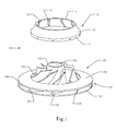
- Fig. 3 depicts a second embodiment of a two-piece shrouded impeller 300 that addresses the issue discussed above.
- the first piece of the two-piece shrouded impeller 300 is a one-piece partially shrouded impeller 320.
- the one-piece partially shrouded impeller 320 has two integral shroud sections: an outer integral shroud 330 and an inner integral shroud 370.
- the outer integral shroud 330 and the inner integral shroud 370 do not meet, but instead leave an open gap between them.
- the gap between outer integral shroud 330 and inner integral shroud 370 forms an annulus 3 80.
- the one-piece partially shrouded impeller 320 has an integrally machined hub 322 and a plurality of blades 350.
- the hub 322 is formed around a bore 324, allowing the hub 322 to be attached to a shaft (not shown) passing through the bore 324.
- the plurality of blades 350 are integrally attached to the hub 322 and are also integrally attached to the outer integral shroud 330 and to the inner integral shroud 370.
- the second piece of the two-piece shrouded impeller 300 is an annular shroud section 310.
- Fig. 3 shows an exploded view of the two-piece shrouded impeller 300 with the one-piece partially shrouded impeller 320 separate from the annular shroud section 310.
- annular shroud section rim 314 is adjacent to an outer integral shroud inner edge 332.
- annular shroud section inner edge 315 is adjacent to an inner integral shroud rim 372.
- the manner in which the annular shroud section 310 attaches to a plurality of blades 350 is discussed below.
- the assembled shroud includes the inner integral shroud 370, the annular shroud section 310 and the outer integral shroud section 330.
- the annular shroud section 310 represents approximately 25% of the completed shroud area.
- the area of the annular shroud section 310 may represent a percentage of the assembled shroud area ranging from 10% to 90% of the assembled shroud.
- the two piece shrouded impeller 300 when assembled, rotates about a shaft (not shown) which passes through a bore 324. Fluid enters the two-piece shrouded impeller 300 through an inlet 342, is impelled by the plurality of blades 350, flowing between the hub 322 and the inner integral shroud 370, the annular shroud section 310 and the outer integral shroud 330, and is expelled through an outlet 344.
- the outlet 344 is bounded by the outer integral shroud 330, the plurality of blades 350, and a floor 360.
- the second embodiment of the two-piece shrouded impeller 300 provides three general areas for attaching the annular shroud section 310 to the one-piece partially shrouded impeller 320: first at the annular shroud section rim 314, second at the annular shroud section inner edge 315, and third at the annular shroud section inner surface 316, which attaches to the plurality of blades 350.
- one-piece partially shrouded impeller 320 may instead be manufactured from two or more assembled pieces.
- the hub 322 may be manufactured separately from the section including inner integral shroud 370 and outer integral shroud 330.
- the hub 322 could be attached to the plurality of blades 350 during assembly after manufacture of the individual pieces.
- Fig. 4 shows a detail of the one-piece partially shrouded impeller 320 ( Fig 3 .) of the second embodiment.
- the outer integral shroud 330 is not shown in this detail to provide a better view of the plurality of blades 350.
- the plurality of blades 350 have axial extensions 352 which raise the plurality of blades 350 above the lower edge of inner integral shroud rim 372.
- the plurality of blade axial extensions 352 are inserted into a plurality of annular shroud section grooves 312 ( Fig. 3 ). This connection may provide strength and accuracy to the two-piece shrouded impeller 300 ( Fig. 3 ) by preventing rotation of the annular shroud section 310 ( Fig. 3 ) in relation to the one-piece partially shrouded impeller 320 ( Fig. 3 ).
- annular shroud section grooves 312 may not be cut into the annular shroud section inner surface 316 ( Fig. 3 ), and instead the annular shroud section inner surface 316 ( Fig. 3 ) may rest directly on the plurality of blades 350, and the plurality of blades 350 may not have axial extensions 352.
- the plurality of blades 350 may be bonded to the annular shroud section inner surface 316 using one of several, but not limited to techniques, for example, brazing, stick welding, ultra sonic welding (US welding), UV welding, electron beam welding
- EBW EBW
- EBW Unlike some other welding techniques, EBW does not add additional material during the welding process. Instead of adding material, EBW melts and mixes the materials of the two surfaces being joined.
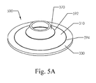
- Fig. 5A shows a detail of an assembled shroud 500 of the second embodiment with the hub 324 ( Fig. 3 ) and the plurality of blades 350 ( Fig. 3 ) omitted for clarity.
- Fig. 5B further shows a cutaway section of the assembled shroud 500.
- annular shroud section rim 314 Fig. 3
- annular shroud inner edge 332 Fig. 3
- annular shroud section inner edge 315 Fig. 3
- annular shroud section inner edge 315 Fig. 3
- the annular shroud section 310 may be attached to the outer integral shroud 330 using several connection techniques.
- Fig. 6 shows a cutaway view of the assembled shroud 500 of the second embodiment.
- the annular shroud section 310 is attached to the outer integral shroud 330 with an annular snap joint (ASJ).
- the ASJ is formed from protruding lip elements that snap into receiving slots as described below.
- the annular shroud section rim 314 is fashioned with an outer protruding lip 614, and the outer integral shroud inner edge 332 is fashioned with an outer receiving slot 632.
- the outer protruding lip 614 fits into the outer receiving slot 632, attaching the annular shroud section 310 to the outer integral shroud 330.
- the blades bound the annular shroud section from below.
- the annular shroud section 310 is also attached to the inner integral shroud 370 with an ASJ.
- the annular shroud section inner edge 315 is fashioned with an inner protruding lip 615
- the inner integral shroud rim 372 is fashioned with an inner receiving slot 672.
- the inner protruding lip 615 fits into the inner receiving slot 672, attaching the annular shroud section 310 to the inner integral shroud 370.
- the outer protruding lip 614 may instead be fashioned on the integral shroud inner edge 332 rather than on the annular shroud section rim 314, and the outer receiving slot 632 may likewise instead be fashioned on the annular shroud section rim 314 instead of on the outer integral shroud inner edge 332.
- the inner receiving slot 672 may instead be fashioned on the annular shroud section rim 315 rather than on the outer receiving slot 632, and the inner protruding lip 615 may likewise instead be fashioned on the inner integral shroud rim 372 instead of on the annular shroud section inner edge 315.
- the outer protruding lip 614 has a triangular, sawtooth shape.
- the outer protruding lip 614 may have other shapes, for example, a V-shaped bead having rounded edges, or a rectangular bead having squared edges.
- the outer receiving slot 632 may be reciprocally shaped to receive the inner protruding lip 614.
- different shapes may be used for inner protruding lip 615 and inner receiving slot 672.
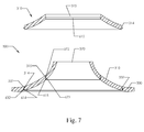
- Fig. 7 depicts a detail of the second embodiment of assembled shroud 500 ( Fig. 5A ).
- Fig. 7 shows two instances of annular shroud section 310: first unassembled and second after being snapped into place in the annulus 380 ( Fig. 3 ) between the inner integral shroud 370 and the outer integral shroud 330. During assembly, the annular shroud section 310 is pressed into the annulus 380 ( Fig. 3 ).
- a compressing force may be exerted upon the annular shroud section 310 by the inner integral shroud rim 372, which may cause the annular shroud section 310 to yield slightly until the inner protruding lip 615 slides past the inner integral shroud rim 372 and engages into the inner receiving slot 672, whereupon the compressing force on the annular shroud section 310 is released and the annular shroud section 310 rebounds to its previous shape.
- the annular shroud section 310 may similarly compress temporarily at the outer edge as the outer protruding lip 614 slides past the annular shroud section rim 314 before engaging with the outer receiving slot 632.
- Alternative embodiments may employ methods other than an AS] for attaching the annular shroud section 310 to the outer integral shroud 330 and the inner integral shroud 370.
- the attachment may be made using a squeeze deformable ring (not shown).
- Such a mechanism may employ two removable compression rings attached to the annular shroud section 310.
- An inner compression ring would be formed as an extension of annular shroud section inner edge 315 and an outer compression ring would be formed as an extension of annular shroud section rim 314.
- As force is applied to press the outer compression ring toward the inner compression ring, the annular shroud section 310 is slightly deformed and compressed.
- the annular shroud section 310 may be pressed into the annulus 380 ( Fig. 3 ), allowing the outer protruding lip 614 to slide past the outer integral shroud inner edge 332, and similarly allowing inner protruding lip 615 to slide past inner integral shroud rim 372. Thereupon the force on the compression rings is released, allowing the annular shroud section 310 to spring back to its previous form, so that the outer protruding lip 614 is inserted into the outer receiving slot 632 and the inner protruding lip 615 is inserted into the inner receiving slot 672.
- the inner compression ring and the outer compression ring may be removed by milling or other means.
- annular shroud section 310 is by using an interference fit.
- an interference fit (not shown), the annular shroud section rim 314 and the outer integral shroud inner edge 332 are formed without protrusions such as the outer protruding lip 614, and without indentations such as the outer receiving slot 632.
- the annular shroud section 310 is formed to fit tightly into the annulus 380.
- annular shroud section 310 When the annular shroud section 310 is pressed into annulus 380, the friction of the annular shroud section rim 314 against the outer integral shroud inner edge 332 holds the annular shroud section 310 in place. Similarly, an interference fit may be used to secure the annular shroud section inner edge 315 to the inner integral shroud rim 372.
- annular shroud section 310 may be further secured by bonding the annular shroud section 310 to the one piece partially shrouded impeller 320 ( Fig. 3 ) using one of several techniques.
- bonding techniques include, brazing, stick welding, ultra sonic welding (US welding), UV welding, electron beam welding (EBW), and other techniques.
- EBW does not add additional material during the welding process. Instead of adding material, EBW melts and mixes the materials of the two surfaces being joined. Because EBW does not add material, there may not be a need to chamfer the edges where the surfaces are being joined, in contrast to techniques that add material during welding. The additional material used in other such welding techniques may add a bead along the connecting edge and thereby impede flow through the impeller.
- Fig. 8 depicts an exploded view of a third embodiment of a two-piece shrouded impeller 800.
- the first piece of the two-piece shrouded impeller 800 is a one-piece "shrouded center" partially shrouded impeller 820.
- the second piece of the two-piece shrouded impeller 800 is an outer ring shroud 810.
- the one-piece shrouded center partially shrouded impeller 820 has a hub 822, an integral partial shroud 830, and a plurality of blades 850.
- the hub 822 is formed around a bore 824, allowing the hub 822 to be attached to a shaft (not shown) passing through the bore 824.
- the plurality of blades 850 are integrally attached to the hub 822 and are also integrally attached to the integral partial shroud 830.
- the integral partial shroud 830 partially covers the plurality of blades 850 under a partial shroud surface spanning from an inner edge 832 of integral partial shroud 830 to an outer rim 834 of integral partial shroud 830.
- the outer ring shroud 810 is manufactured separately from the one-piece shrouded center partially shrouded impeller 820. When assembled, the outer ring shroud 810 attaches to the one-piece shrouded center partially shrouded impeller 820, further enclosing the plurality of blades 850.
- the plurality of grooves 812 correspond to the plurality of blades 850, so that the plurality of blades 850 fit into the plurality of grooves 812 when the outer ring shroud 810 and the one-piece shrouded center partially shrouded impeller 820 are assembled.
- a connecting edge 814 of the outer ring shroud 810 is adj acent to an outer rim 834 of integral partial shroud 830, forming a seam 890 as shown in Fig. 9 .
- Fig. 9 depicts a second view of the third embodiment of the two-piece shrouded impeller 800 where the outer ring shroud 810 and the one-piece shrouded center partially shrouded impeller 820 ( Fig. 8 ) are assembled.
- the two-piece shrouded impeller 800 rotates around a shaft (not shown) passing through the bore 824. Fluid enters the two-piece shrouded impeller 800 through an inlet 842, is impelled by the plurality of blades 850, passing between the hub 822 and the integral partial shroud 830 and the outer ring shroud 810, and exits through an outlet 844.
- the outlet 844 is bounded by the outer ring shroud 810, the plurality of blades 850, and a floor 860.
- the outer ring shroud 810 may be attached to the one piece shrouded center partially shrouded impeller 820 by the attachment methods discussed previously, for example, a snap joint, a squeeze deformable ring, or an interference fit.
- a plurality of grooves 812 are formed into an inner surface 816 ( Fig. 8 ) of the outer ring shroud 810.
- the plurality of blades 850 are inserted into the plurality of grooves 812 ( Fig. 8 ).
- outer ring shroud 810 and one piece shrouded center partially shrouded impeller 820 may be bonded together by using one of the bonding techniques described previously, including brazing, stick welding, US welding, UV welding, EBW, and other techniques.
- inner surface 816 of outer ring shroud 8] 0 may be implemented without a plurality of grooves 812, and instead the plurality of blades 850 are bonded directly to the inner surface 816.
- Fig. 10 shows an exploded view of a three-piece shrouded impeller 1000.
- the first piece of the three-piece shrouded impeller 1000 is a one-piece middle ring partially shrouded impeller 1020.
- the second piece of the three-piece shrouded impeller 1000 is an outer ring shroud section 1010, and the third piece is an inner ring shroud section 1070.
- the outer ring shroud section 10 10 is attached to the one-piece middle ring partially shrouded impeller 1020 using attachment methods described previously.
- the inner ring shroud section 1070 is attached to the one-piece middle ring partially shrouded impeller 1020 using attachment methods described previously.
Landscapes
- Engineering & Computer Science (AREA)
- Mechanical Engineering (AREA)
- General Engineering & Computer Science (AREA)
- Ceramic Engineering (AREA)
- Structures Of Non-Positive Displacement Pumps (AREA)
Applications Claiming Priority (1)
| Application Number | Priority Date | Filing Date | Title |
|---|---|---|---|
| US12/825,381 US8727729B2 (en) | 2010-06-29 | 2010-06-29 | Method for producing a shrouded impeller from two or more components |
Publications (2)
| Publication Number | Publication Date |
|---|---|
| EP2402112A2 true EP2402112A2 (fr) | 2012-01-04 |
| EP2402112A3 EP2402112A3 (fr) | 2012-09-26 |
Family
ID=44352174
Family Applications (1)
| Application Number | Title | Priority Date | Filing Date |
|---|---|---|---|
| EP11171943A Withdrawn EP2402112A3 (fr) | 2010-06-29 | 2011-06-29 | Procédé de production de turbine carénée à partir d'au moins deux composants |
Country Status (2)
| Country | Link |
|---|---|
| US (1) | US8727729B2 (fr) |
| EP (1) | EP2402112A3 (fr) |
Cited By (8)
| Publication number | Priority date | Publication date | Assignee | Title |
|---|---|---|---|---|
| ITFI20120035A1 (it) * | 2012-02-23 | 2013-08-24 | Nuovo Pignone Srl | "produzione di giranti per turbo-macchine" |
| CN103573691A (zh) * | 2012-07-27 | 2014-02-12 | 通用汽车环球科技运作有限责任公司 | 泵叶轮 |
| US9091277B1 (en) | 2014-04-25 | 2015-07-28 | Computer Assisted Manufacturing Technology Corporation | Systems and methods for manufacturing a shrouded impeller |
| EP3156591A1 (fr) * | 2015-10-14 | 2017-04-19 | Atlas Copco Energas GmbH | Roue de turbine pour turbine radiale |
| EP3205825A1 (fr) * | 2016-02-11 | 2017-08-16 | General Electric Company | Compresseur centrifuge à utiliser dans un moteur de turbine et procédé d'assemblage |
| US9945388B2 (en) | 2013-02-20 | 2018-04-17 | Nuovo Pignone Srl | Method for making an impeller from sector segments |
| CN112917110A (zh) * | 2021-02-25 | 2021-06-08 | 南京中科神光科技有限公司 | 大型窄流道闭式叶轮、制造方法及叶片专用焊接设备 |
| EP3115613B1 (fr) | 2015-07-06 | 2022-01-26 | Zhejiang Sanhua Automotive Components Co., Ltd. | Pompe à entraînement électrique |
Families Citing this family (48)
| Publication number | Priority date | Publication date | Assignee | Title |
|---|---|---|---|---|
| CN102762873A (zh) * | 2010-02-17 | 2012-10-31 | 松下电器产业株式会社 | 叶轮、使用了叶轮的电动鼓风机及使用了电动鼓风机的吸尘器 |
| FR2973847B1 (fr) * | 2011-04-11 | 2015-10-30 | Pellenc Sa | Helice de generateur de flux d'air pulse, en particulier pour souffleur portatif. |
| KR101871942B1 (ko) * | 2012-02-15 | 2018-07-02 | 한화에어로스페이스 주식회사 | 회전 기계의 회전체 및 회전 기계의 회전체 제조 방법 |
| CN102528403A (zh) * | 2012-02-15 | 2012-07-04 | 德谦杭重锻造有限公司 | 汽轮机叶轮自由锻造双凸成形工艺 |
| US9033670B2 (en) * | 2012-04-11 | 2015-05-19 | Honeywell International Inc. | Axially-split radial turbines and methods for the manufacture thereof |
| US9115586B2 (en) | 2012-04-19 | 2015-08-25 | Honeywell International Inc. | Axially-split radial turbine |
| NO334130B1 (no) * | 2012-09-07 | 2013-12-16 | Dynavec As | Anordning ved løpehjul for hydraulisk strømningsmaskin |
| JP5977693B2 (ja) * | 2012-09-26 | 2016-08-24 | 日立オートモティブシステムズ株式会社 | インペラおよびウォーターポンプ |
| KR101612854B1 (ko) * | 2012-12-18 | 2016-04-26 | 한화테크윈 주식회사 | 유체 회전 기계의 임펠러 조립체 |
| KR101501477B1 (ko) | 2013-03-25 | 2015-03-12 | 두산중공업 주식회사 | 원심압축기 |
| KR101465052B1 (ko) | 2013-04-12 | 2014-11-25 | 두산중공업 주식회사 | 원심압축기의 쉬라우드 임펠러 및 그 제조방법 |
| US9476305B2 (en) | 2013-05-13 | 2016-10-25 | Honeywell International Inc. | Impingement-cooled turbine rotor |
| KR102126866B1 (ko) | 2013-08-07 | 2020-06-25 | 한화파워시스템 주식회사 | 유체 회전 기계의 임펠러 조립체 및 임펠러 조립체의 제조 방법 |
| WO2015163925A1 (fr) * | 2014-04-25 | 2015-10-29 | Computer Assisted Manufacturing Technology Corporation Dba Camtech | Systèmes et procédés pour fabriquer une roue fermée |
| RU2688985C2 (ru) * | 2014-05-26 | 2019-05-23 | Нуово Пиньоне СРЛ | Способ изготовления компонента турбомашины |
| KR102208490B1 (ko) * | 2014-07-07 | 2021-01-27 | 한화에어로스페이스 주식회사 | 회전 기계의 회전부 제조 방법 |
| DE102014012425B4 (de) | 2014-08-22 | 2024-06-06 | Concept Laser Gmbh | Verfahren zum Herstellen eines dreidimensionalen Objekts |
| US9850760B2 (en) * | 2015-04-15 | 2017-12-26 | Honeywell International Inc. | Directed cooling for rotating machinery |
| CN105587686A (zh) * | 2016-01-31 | 2016-05-18 | 嘉善卡固电气设备有限公司 | 离心风机的叶轮 |
| US10100840B2 (en) * | 2016-03-08 | 2018-10-16 | Asia Vital Components Co., Ltd. | Fan wheel structure |
| US10400780B2 (en) * | 2016-03-08 | 2019-09-03 | Asia Vital Components Co., Ltd. | Structure of fan blades |
| US10480525B2 (en) * | 2016-03-08 | 2019-11-19 | Asia Vital Components Co., Ltd. | Fan blade with improved structure |
| CA2966053C (fr) * | 2016-05-05 | 2022-10-18 | Tti (Macao Commercial Offshore) Limited | Ventilateur a flux melange |
| EP3251787B1 (fr) | 2016-05-31 | 2024-08-14 | Sulzer Management AG | Procédé de fabrication d'un composant de machine rotative et composant fabriqué selon un tel procédé |
| DE102016120480A1 (de) * | 2016-10-27 | 2018-05-03 | Man Diesel & Turbo Se | Verfahren zum Herstellen eines Strömungsmaschinenlaufrads |
| DE102016222312B4 (de) * | 2016-11-14 | 2025-12-31 | Everllence Se | Strömungsmaschinenrotor und Verfahren zum Herstellen desselben |
| US10641282B2 (en) * | 2016-12-28 | 2020-05-05 | Nidec Corporation | Fan device and vacuum cleaner including the same |
| DE102017117100A1 (de) * | 2017-07-28 | 2019-01-31 | Ebm-Papst Mulfingen Gmbh & Co. Kg | Laufradteilung eines zweiteiligen Ventilatorrades |
| KR102069575B1 (ko) | 2018-02-08 | 2020-01-23 | 엘지전자 주식회사 | 임펠러의 제조 방법 |
| EP3530956B1 (fr) * | 2018-02-26 | 2021-09-22 | Honeywell Technologies Sarl | Roue à aubes pour soufflante radiale et appareil à brûleur à gaz |
| DE102018108762A1 (de) * | 2018-04-12 | 2019-10-17 | Gühring KG | Absaugvorrichtung mit Schaufeln sowie hierfür vorgesehenes Herstellungsverfahren |
| CN109014905B (zh) * | 2018-09-04 | 2024-04-02 | 深圳市源博旺科技有限公司 | 一种自动化风轮组装设备 |
| JP7149174B2 (ja) * | 2018-12-10 | 2022-10-06 | ダイキン工業株式会社 | クローズドインペラ及びその製造方法 |
| US11218048B2 (en) | 2018-12-14 | 2022-01-04 | Nidec Motor Corporation | Shaft-mounted slinger for electric motor |
| US11565481B2 (en) | 2019-07-01 | 2023-01-31 | Hamilton Sundstrand Corporation | Method of welding additively manufactured thermoplastic |
| WO2021030440A1 (fr) * | 2019-08-13 | 2021-02-18 | Emerson Climate Technologies, Inc. | Procédés de fabrication d'une roue fermée, roue fermée et compresseur |
| KR102546910B1 (ko) * | 2019-09-25 | 2023-06-23 | 아쏘마 아이엔씨. | 원심 펌프의 3 차원 플라스틱 임펠러 제조 방법 및 임펠러 |
| WO2021118916A1 (fr) * | 2019-12-09 | 2021-06-17 | Danfoss A/S | Agencement de roue carénée de compresseur |
| KR102822545B1 (ko) * | 2020-03-12 | 2025-06-19 | 엘지전자 주식회사 | 임펠러 |
| EP3901469B1 (fr) | 2020-04-20 | 2025-09-03 | Hamilton Sundstrand Corporation | Hélice |
| DE102020114389A1 (de) * | 2020-05-28 | 2021-12-02 | Ebm-Papst Mulfingen Gmbh & Co. Kg | Gebläserad mit ener nahtlosen Anbindung der Laufradschaufeln an einen Scheibenkörper |
| US11441572B2 (en) | 2020-08-24 | 2022-09-13 | Hamilton Sundstrand Corporation | Impeller design and manufacturing method with pentagonal channel geometry |
| US12370615B2 (en) * | 2021-03-05 | 2025-07-29 | Danfoss A/S | Techniques for applying brazing material to form a shrouded impeller |
| US11486498B1 (en) * | 2021-09-10 | 2022-11-01 | Hamilton Sundstrand Corporation | Dynamic sealing labyrinth seals |
| JP2023113428A (ja) * | 2022-02-03 | 2023-08-16 | 三菱重工業株式会社 | インペラおよび回転機械 |
| GB202218545D0 (en) * | 2022-12-09 | 2023-01-25 | Cummins Generator Technologies | Fan for rotating electrical machine |
| CN117823455B (zh) * | 2023-12-29 | 2024-06-14 | 无锡艾尔泰科压缩机有限公司 | 一种离心式压缩机用压缩闭式叶轮 |
| CN120576122B (zh) * | 2025-06-12 | 2025-11-28 | 成都漩奇科技有限公司 | 一种闭式叶轮以及制造方法 |
Family Cites Families (23)
| Publication number | Priority date | Publication date | Assignee | Title |
|---|---|---|---|---|
| US2625365A (en) | 1949-02-26 | 1953-01-13 | Curtiss Wright Corp | Shrouded impeller |
| US3159106A (en) | 1962-03-21 | 1964-12-01 | Allis Chalmers Mfg Co | Impeller and method of making same |
| US3224079A (en) * | 1964-12-28 | 1965-12-21 | Ruth D Mayne | Method for manufacture of turbine type blower wheels |
| FI54186C (fi) | 1976-05-11 | 1978-10-10 | Sarlin Ab Oy E | Loephjul |
| JPS5968599A (ja) | 1982-10-13 | 1984-04-18 | Hitachi Ltd | スラリ−ポンプ用遠心羽根車 |
| US5445215A (en) | 1992-12-22 | 1995-08-29 | Herbert; Edward | Fan assembly with heat sink |
| JP4031062B2 (ja) * | 1995-08-11 | 2008-01-09 | 株式会社荏原製作所 | プラスチック製部品及びその製造方法 |
| US6280493B1 (en) | 1999-03-19 | 2001-08-28 | Dreison International, Inc. | Air pre-cleaner |
| US6081423A (en) * | 1998-12-22 | 2000-06-27 | The Esab Group, Inc. | Power supply with obliquely impinging airflow |
| US6276899B1 (en) * | 1999-11-05 | 2001-08-21 | Flowserve Management Company | Impeller manufacturing process |
| US6474938B2 (en) | 2000-04-17 | 2002-11-05 | Coltec Industries Inc | Fuel pump for gas turbines |
| US7371139B1 (en) | 2003-04-02 | 2008-05-13 | Jose Abella | Nozzle drive propulsion for a marine craft |
| US20050071998A1 (en) | 2003-10-02 | 2005-04-07 | Rocky Drew M. | Method of molding centrifugal impeller |
| DE10354750A1 (de) | 2003-11-21 | 2005-06-23 | Siemens Ag | Verfahren zur Herstellung eines Laufrades für eine Kreiselpumpe |
| US7108482B2 (en) * | 2004-01-23 | 2006-09-19 | Robert Bosch Gmbh | Centrifugal blower |
| US7632073B2 (en) | 2005-06-08 | 2009-12-15 | Dresser-Rand Company | Impeller with machining access panel |
| US7281675B2 (en) | 2005-08-15 | 2007-10-16 | Marcos Elrod | Portable particle spreader/blower |
| US7628586B2 (en) | 2005-12-28 | 2009-12-08 | Elliott Company | Impeller |
| US20070163114A1 (en) | 2006-01-13 | 2007-07-19 | General Electric Company | Methods for fabricating components |
| US8534992B2 (en) | 2007-03-23 | 2013-09-17 | Flodesign Wind Turbine Corp. | Wind turbine |
| JP2009024571A (ja) | 2007-07-19 | 2009-02-05 | Shin Meiwa Ind Co Ltd | 遠心ポンプ用羽根車およびそれを備えた遠心ポンプ |
| US20100111698A1 (en) * | 2008-11-06 | 2010-05-06 | Bryce Wiedeman | Fan with locking ring |
| IT1394295B1 (it) * | 2009-05-08 | 2012-06-06 | Nuovo Pignone Spa | Girante centrifuga del tipo chiuso per turbomacchine, componente per tale girante, turbomacchina provvista di tale girante e metodo di realizzazione di tale girante |
-
2010
- 2010-06-29 US US12/825,381 patent/US8727729B2/en active Active
-
2011
- 2011-06-29 EP EP11171943A patent/EP2402112A3/fr not_active Withdrawn
Non-Patent Citations (1)
| Title |
|---|
| None |
Cited By (15)
| Publication number | Priority date | Publication date | Assignee | Title |
|---|---|---|---|---|
| US9903207B2 (en) | 2012-02-23 | 2018-02-27 | Nuovo Pignone Srl | Turbo-machine impeller manufacturing |
| ITFI20120035A1 (it) * | 2012-02-23 | 2013-08-24 | Nuovo Pignone Srl | "produzione di giranti per turbo-macchine" |
| CN104284746A (zh) * | 2012-02-23 | 2015-01-14 | 诺沃皮尼奥内股份有限公司 | 涡轮机叶轮制造 |
| RU2630139C2 (ru) * | 2012-02-23 | 2017-09-05 | Нуово Пиньоне СРЛ | Изготовление импеллера турбомашины |
| EP2817117B1 (fr) | 2012-02-23 | 2020-08-05 | Nuovo Pignone S.r.l. | Fabrication d'hélice de turbine |
| WO2013124314A1 (fr) * | 2012-02-23 | 2013-08-29 | Nuovo Pignone Srl | Fabrication d'hélice de turbine |
| CN103573691A (zh) * | 2012-07-27 | 2014-02-12 | 通用汽车环球科技运作有限责任公司 | 泵叶轮 |
| US9945388B2 (en) | 2013-02-20 | 2018-04-17 | Nuovo Pignone Srl | Method for making an impeller from sector segments |
| US9091277B1 (en) | 2014-04-25 | 2015-07-28 | Computer Assisted Manufacturing Technology Corporation | Systems and methods for manufacturing a shrouded impeller |
| EP3115613B1 (fr) | 2015-07-06 | 2022-01-26 | Zhejiang Sanhua Automotive Components Co., Ltd. | Pompe à entraînement électrique |
| EP3156591A1 (fr) * | 2015-10-14 | 2017-04-19 | Atlas Copco Energas GmbH | Roue de turbine pour turbine radiale |
| EP3205825A1 (fr) * | 2016-02-11 | 2017-08-16 | General Electric Company | Compresseur centrifuge à utiliser dans un moteur de turbine et procédé d'assemblage |
| CN107061344A (zh) * | 2016-02-11 | 2017-08-18 | 通用电气公司 | 用于涡轮发动机的离心压缩机组件和组装方法 |
| US10227879B2 (en) | 2016-02-11 | 2019-03-12 | General Electric Company | Centrifugal compressor assembly for use in a turbine engine and method of assembly |
| CN112917110A (zh) * | 2021-02-25 | 2021-06-08 | 南京中科神光科技有限公司 | 大型窄流道闭式叶轮、制造方法及叶片专用焊接设备 |
Also Published As
| Publication number | Publication date |
|---|---|
| EP2402112A3 (fr) | 2012-09-26 |
| US20110318183A1 (en) | 2011-12-29 |
| US8727729B2 (en) | 2014-05-20 |
Similar Documents
| Publication | Publication Date | Title |
|---|---|---|
| US8727729B2 (en) | Method for producing a shrouded impeller from two or more components | |
| US9441491B2 (en) | Shroud impeller of centrifugal compressor and method of manufacturing the same | |
| EP2784327B1 (fr) | Compresseur centrifuge | |
| US8061031B2 (en) | Method of finish machining an impeller | |
| EP1971782B1 (fr) | Roue a aubes | |
| SE519781C2 (sv) | Förfarande för framställning av en stator-eller rotorkomponent | |
| EP1526252A3 (fr) | Rotor de turbine de triple caractère et sa méthode de production | |
| EP3659741B1 (fr) | Joint hydrostatique assemblé doté de plusieurs composants | |
| EP4134553B1 (fr) | Impulseur fermé et procédé de production d'un impulseur fermé | |
| JP2016148308A (ja) | 遠心圧縮機、及びギアード遠心圧縮機 | |
| US11261875B2 (en) | Turbomachine stage and method of making same | |
| KR20190096219A (ko) | 임펠러의 제조 방법 | |
| US20140377070A1 (en) | Axial Turbomachine Compressor Drum with Dual Means of Blade Fixing | |
| JP7292858B2 (ja) | 羽根車、該羽根車を備えたポンプ、および該羽根車の製造方法 | |
| US20180050422A1 (en) | Method for manufacturing compressor components | |
| WO2016166909A1 (fr) | Machine rotative et procédé pour fabriquer une machine rotative | |
| EP1207296A1 (fr) | Pompe de combustible résistant à l'usure | |
| HK1164787A (en) | Method for producing a shrouded impeller from two or more components | |
| EP2975221A1 (fr) | Ensemble d'aube | |
| EP2309099B1 (fr) | Conduit de transition | |
| US12370615B2 (en) | Techniques for applying brazing material to form a shrouded impeller | |
| JPH08303389A (ja) | 遠心羽根車及び該遠心羽根車の製造方法 | |
| US20110150662A1 (en) | Blade families for torque converters | |
| US12209512B2 (en) | Group of stator vanes | |
| JP2019094900A (ja) | タービンガイド装置 |
Legal Events
| Date | Code | Title | Description |
|---|---|---|---|
| AK | Designated contracting states |
Kind code of ref document: A2 Designated state(s): AL AT BE BG CH CY CZ DE DK EE ES FI FR GB GR HR HU IE IS IT LI LT LU LV MC MK MT NL NO PL PT RO RS SE SI SK SM TR |
|
| AX | Request for extension of the european patent |
Extension state: BA ME |
|
| PUAI | Public reference made under article 153(3) epc to a published international application that has entered the european phase |
Free format text: ORIGINAL CODE: 0009012 |
|
| PUAL | Search report despatched |
Free format text: ORIGINAL CODE: 0009013 |
|
| AK | Designated contracting states |
Kind code of ref document: A3 Designated state(s): AL AT BE BG CH CY CZ DE DK EE ES FI FR GB GR HR HU IE IS IT LI LT LU LV MC MK MT NL NO PL PT RO RS SE SI SK SM TR |
|
| AX | Request for extension of the european patent |
Extension state: BA ME |
|
| RIC1 | Information provided on ipc code assigned before grant |
Ipc: F01D 5/04 20060101ALN20120817BHEP Ipc: F04D 29/26 20060101ALN20120817BHEP Ipc: B23P 15/00 20060101AFI20120817BHEP Ipc: F04D 29/22 20060101ALN20120817BHEP |
|
| REG | Reference to a national code |
Ref country code: HK Ref legal event code: DE Ref document number: 1164787 Country of ref document: HK |
|
| 17P | Request for examination filed |
Effective date: 20130326 |
|
| 17Q | First examination report despatched |
Effective date: 20180104 |
|
| STAA | Information on the status of an ep patent application or granted ep patent |
Free format text: STATUS: THE APPLICATION HAS BEEN WITHDRAWN |
|
| 18W | Application withdrawn |
Effective date: 20180411 |
|
| REG | Reference to a national code |
Ref country code: HK Ref legal event code: WD Ref document number: 1164787 Country of ref document: HK |