EP2402183B1 - Climatisation de véhicule automobile - Google Patents
Climatisation de véhicule automobile Download PDFInfo
- Publication number
- EP2402183B1 EP2402183B1 EP10290350.7A EP10290350A EP2402183B1 EP 2402183 B1 EP2402183 B1 EP 2402183B1 EP 10290350 A EP10290350 A EP 10290350A EP 2402183 B1 EP2402183 B1 EP 2402183B1
- Authority
- EP
- European Patent Office
- Prior art keywords
- flap
- air
- conditioning system
- fresh air
- wing
- Prior art date
- Legal status (The legal status is an assumption and is not a legal conclusion. Google has not performed a legal analysis and makes no representation as to the accuracy of the status listed.)
- Not-in-force
Links
Images


Classifications
-
- B—PERFORMING OPERATIONS; TRANSPORTING
- B60—VEHICLES IN GENERAL
- B60H—ARRANGEMENTS OF HEATING, COOLING, VENTILATING OR OTHER AIR-TREATING DEVICES SPECIALLY ADAPTED FOR PASSENGER OR GOODS SPACES OF VEHICLES
- B60H1/00—Heating, cooling or ventilating devices
- B60H1/00642—Control systems or circuits; Control members or indication devices for heating, cooling or ventilating devices
- B60H1/00664—Construction or arrangement of damper doors
- B60H1/00671—Damper doors moved by rotation; Grilles
- B60H1/00685—Damper doors moved by rotation; Grilles the door being a rotating disc or cylinder or part thereof
-
- B—PERFORMING OPERATIONS; TRANSPORTING
- B60—VEHICLES IN GENERAL
- B60H—ARRANGEMENTS OF HEATING, COOLING, VENTILATING OR OTHER AIR-TREATING DEVICES SPECIALLY ADAPTED FOR PASSENGER OR GOODS SPACES OF VEHICLES
- B60H1/00—Heating, cooling or ventilating devices
- B60H1/00642—Control systems or circuits; Control members or indication devices for heating, cooling or ventilating devices
- B60H1/00814—Control systems or circuits characterised by their output, for controlling particular components of the heating, cooling or ventilating installation
- B60H1/00821—Control systems or circuits characterised by their output, for controlling particular components of the heating, cooling or ventilating installation the components being ventilating, air admitting or air distributing devices
- B60H1/00835—Damper doors, e.g. position control
- B60H1/00849—Damper doors, e.g. position control for selectively commanding the induction of outside or inside air
-
- B—PERFORMING OPERATIONS; TRANSPORTING
- B60—VEHICLES IN GENERAL
- B60H—ARRANGEMENTS OF HEATING, COOLING, VENTILATING OR OTHER AIR-TREATING DEVICES SPECIALLY ADAPTED FOR PASSENGER OR GOODS SPACES OF VEHICLES
- B60H1/00—Heating, cooling or ventilating devices
- B60H1/00007—Combined heating, ventilating, or cooling devices
- B60H1/00021—Air flow details of HVAC devices
- B60H2001/00078—Assembling, manufacturing or layout details
- B60H2001/00085—Assembling, manufacturing or layout details of air intake
Definitions
- the invention relates to an automotive air conditioning system according to the preamble of claim 1.
- Automotive air conditioning systems serve to heat and / or to cool the air to be supplied to the interior of a motor vehicle.
- the motor vehicle air conditioners are provided with various designed as louvers louvers.
- the louvers are used for. B. to control whether the vehicle interior air from the environment or from the vehicle interior is supplied.
- These air flaps are referred to as recirculation flaps
- the motor vehicle air conditioner also has additional air dampers which serve to control the amount of air that can be conducted into the vehicle interior.
- actuators for example, actuators with a gear and an electric motor.
- flag flaps As recirculation flaps so-called flag flaps are used, which have only one flap wing on a rotation axis. When closing a fresh air duct into which opens a fresh air inlet opening, with the help of the flag flap, acts on this flag flap at a high speed of a motor vehicle, a large back pressure. Since the flag flap has only one flap wing, this creates a large torque on the axis of rotation, which must be absorbed by a transmission or an actuator. Therefore, there is rattling or whistling and it is only an insufficient seal at such a high dynamic pressure with the help of this flag flap possible.
- the post-published EP 2 322 367 A1 shows an automotive air conditioning system according to the preamble of claim 1.
- the object of the present invention is therefore to provide an automotive air conditioning system with a recirculating air flap, in which a recirculating air flap can be reliably sealed off in a rectangular cross-section fresh air duct even at a large dynamic pressure.
- the motor vehicle air conditioning system only has one recirculation air flap.
- the butterfly flap is mounted pivotably about an axis of rotation and the butterfly flap has a first flap wing and a second flap wing, preferably, the first and second flap wing is formed opposite to the rotation axis.
- the butterfly flap has the first and second flap wings, and with the first and second flap wings, the fresh air channel is closed in the circulating air position of the butterfly flap, so that a high dynamic pressure acting on the butterfly flap in the fresh air channel acts both on the first flap wing and on the second flap wing, and characterized in that the torque acting on the axis of rotation is at least partially canceled, because the torque acting on the first flap wing is directed opposite to the acting on the second flap wing torque or the second flap wing emerging or acting torque opposite. Even in the fresh air position of the butterfly flap of the first and second flap wing of the circulating air channel is closed.
- a first plane spanned by the first flap wing and a second plane spanned by the second flap wing are aligned substantially parallel to one another, and preferably the distance of the first plane from the second plane perpendicular to the first and / or second plane is smaller than at the butterfly flap 3 cm or 2 cm or is zero.
- Essentially oriented parallel to one another according to the invention means that the first plane and the second plane are aligned at an angle of less than 30 °, 20 °, 10 ° or 5 ° to each other, in particular in a section perpendicular to the axis of rotation.
- the ratio of the extent of the first flap wing in the direction of the first plane to the extension of the second flap wing in the direction of the second plane, each in a section perpendicular to the axis of rotation between 1 and 1.8, preferably between 1 and 1.5.
- the first flap wing and the second flap wing are curved.
- first flap wing and / or the second flap wing are curved in a section perpendicular to the axis of rotation.
- first flap wing and / or the second flap wing are aligned at a distance from the axis of rotation.
- the distance is between 0.1 and 4 cm, in particular between 0.5 and 3 cm.
- the first plane and / or the second plane are aligned at the distance to the axis of rotation.
- a first and second retaining wall is formed on the first flap wing and / or on the second flap wing, and preferably, the first and second retaining walls are aligned substantially perpendicular to the axis of rotation.
- the extent of the fresh air channel is perpendicular to the flow direction of the fresh air in the fresh air passage in the direction of a first axis greater than in the direction of a second axis and the first and second axes are perpendicular to each other.
- the first and second axes lie in a plane, wherein the plane is aligned in particular perpendicular to the flow direction of the fresh air in the fresh air passage and / or a longitudinal axis of the fresh air passage.
- the extent of the fresh air duct in the direction of the first axis is at least 2, 3, 5, 7 or 10 times greater than in the direction of the second axis and / or the fresh air duct has a substantially rectangular cross section on.
- first axis and the second axis are aligned perpendicular to the flow direction of the fresh air.
- the recirculation flap has a sealing edge, z. As an edge of an elastic material or a foam seal, on.
- the sealing edge serves to ensure that when the recirculation flap on the housing or a wall of the housing a substantially complete seal with the help of the recirculation damper is possible.
- the at least one circulating air flap is connected by means of a sliding bearing with the housing.
- the motor vehicle air conditioning system comprises an actuator, for. As an electric motor, and a mechanism or a transmission and the actuator is mechanically connected to the recirculation damper (by means of the mechanism or the transmission), so that the at least one recirculation damper by means of the mechanism or transmission of the actuator is movable.
- the motor vehicle air conditioning system comprises a fan and / or a refrigerant evaporator and / or a heating device and / or the supply channel leads to the fan and / or the refrigerant evaporator and / or the heating device.
- the plastic of the sealing edge has greater elastic properties than the plastic of the at least one air flap outside the sealing edge, for example, the sealing edge of a soft plastic and the rest of the air damper of a hard plastic.
- the housing and the at least one air flap are produced in one piece with injection molding, in particular made of plastic.
- the housing and / or the at least one air flap made of thermoplastic and / or thermosetting and / or elastomeric plastic or is made from this.
- the housing of the motor vehicle air conditioning system is one or more parts.
- the motor vehicle air conditioning system has at least one air flap or a roller blind in order to control the quantity of air that can be conducted through an air duct.
- the housing of the motor vehicle air conditioning system consists of the same or a different plastic than the at least one air flap.
- the actuator is an electric motor or a piezoelectric element.
- the motor vehicle air conditioning system preferably has at least one air duct for the passage of air.
- the housing of the motor vehicle air conditioning at least partially made of plastic.
- the fresh air duct and / or the circulating air duct and / or the supply duct are delimited by a wall of the housing.
- the actuator has a position detection device for detecting the position of the mechanism, for. As a wave on.
- the position detection unit is connected to a control unit for the motor vehicle air conditioning system and controllable by means of the data detected by the position detection unit of the actuator to achieve a specific position of the mechanism or the at least one air damper.
- Automotive air conditioning systems 1 serve to cool and / or heat the air to be supplied to a vehicle interior of a motor vehicle.
- the motor vehicle air conditioning system 1 comprises a housing 2 made generally of thermoplastic material.
- the housing 2 is formed with walls which also define an air duct, for example as a fresh air duct 5, recirculating air duct 6 and / or supply air duct 7. Through the air duct to be cooled and / or heated air is passed.
- a refrigerant evaporator and a heater not shown, for example, an electric heater and / or a heat exchanger through which coolant of an internal combustion engine is passed to transfer heat from the coolant to the air channeled through the air duct.
- the housing 1 also serves to receive a fan (not shown).
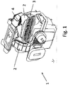
- the multipart housing 2 has a fresh air inlet opening 3 and a recirculation inlet opening 4 ( Fig. 1 to 3 ).
- the fresh air inlet opening 3 has a substantially rectangular cross section, and the length of the fresh air inlet opening 3 is substantially greater than the height or the width of the fresh air inlet opening 3
- FIGS. 2 and 3 a part of the housing 2 is shown with a recirculating air flap 8 designed as a butterfly flap 9.
- the fresh air inlet opening 3 opens into the fresh air channel 5 and the recirculation inlet opening 4 opens into the recirculation channel 6. Both the fresh air channel 5 and the recirculating air channel 6 open into the feed air channel 7.
- the butterfly flap 9 about an axis of rotation 10th swiveling between a fresh air position and a recirculation position.
- the butterfly flap 9 is mounted as a recirculating air flap 8 by means of two bearing pins 17 on the housing 2 as a sliding bearing.
- Fig. 2 and 5 the recirculation position of the recirculating air flap 8 is shown.
- the fresh air duct 5 or the fresh air inlet opening 3 is closed by the recirculation damper 8 and the recirculation inlet opening 4 or the circulating air duct 6 is opened.
- Fig. 1 the butterfly flap 9 about an axis of rotation 10th swiveling between a fresh air position and a recirculation position.
- the butterfly flap 9 is mounted as a recirculating air flap 8 by means of two bearing pins 17 on the housing 2 as a sliding bearing.
- Fig. 2 and 5 the recirculation position of the recirculating air flap 8 is shown.
- the butterfly flap 9 has a first flap wing 11 and a second flap wing 12.
- the first flap wing 11 essentially clamps a first plane 13 (FIG. Fig. 4 ) and the second flap wing 12 biases a second plane 14.
- the first and second flap wings 11, 12 also also have a slight curvature.
- the first and second plane 13, 14 is thus not completely within the first and second flap wing 11, 12, but is only approximately inside the first and second flap wings 11, 12.
- the first plane 13 is placed in the first flap wing 11 in such a way that one end according to the section in FIG Fig.
- the extension of the first flap wing 11 in the direction of according to the first level in the section Fig. 4 is in Fig. 4 marked with a and the extension of the second flap wing 12 in the direction of the second plane 14 in the section perpendicular to the axis of rotation 10 according to Fig. 4 in Fig. 4 is marked with b.
- the ratio of a and b is greater than 1 and is in the range between 1.2 and 1.4.
- the extent a of the first flap wing 11 is thus greater than the extent b of the second flap wing 12.
- the butterfly flap 9 furthermore has a sealing edge 18 made of an elastic material and furthermore a first retaining wall 15 and a second retaining wall 16 are formed on the butterfly flap 9 (FIG. FIGS. 2 and 3 ). At the first and second retaining wall 15, 16 each have a bearing pin 17 is arranged, by means of which the butterfly flap 9 is mounted on the housing 2.
- the housing 2 and the butterfly valves 9 are made by injection molding of plastic.
- the circulating air flap 8 acts at a high driving speed of the motor vehicle with the Kraft povertykümastrom 1 a high back pressure on the butterfly valve 9.
- This high back pressure acts both on the first flap wing 11 and on the second flap wing 12. Due to geometric alignment of the first and second flap wing 11, 12 to the rotation axis 10 and the two bearing pins 17 is to receive 17 of the two bearing pin 17 only a very small torque, because the slightly larger torque, which arises at the slightly larger first flap wing 11, is substantially canceled by the resulting torque at the second flap wing 12.
- the first and second flap wings 11, 12 has a curvature. This is in the fresh air position ( Fig. 3 and 4 ), a larger flow path of the fresh air from the fresh air inlet port 3 to the supply air passage 7 is possible.
- circulating air position of the recirculating air flap 8 causes the curvature of the first and second flap wing 11, 12 a reduced flow cross-sectional area of the circulating air, which is passed through the recirculation inlet opening 4 to the supply air duct 7.
- sucking circulating air from the vehicle interior in the circulating air position of the butterfly flap 9 lower flow resistances generally occur due to the shorter flow path, so that the reduced flow cross-sectional area of the circulating air in the circulating air position of the butterfly flap 9 is desired.
- the recirculating-air flap 8 designed as a butterfly flap 9 makes it possible to seal the fresh-air channel 5 reliably and without rattling even in the case of a high dynamic pressure acting on the recirculating-air flap 8 in a circulating-air position.
- the axis of rotation 10 of the butterfly flap 9 is substantially aligned, that is, with a deviation of less than 30 °, 20 °, 10 ° or 5 °, parallel to the second axis of the fresh air channel 5.
- the first axis and the second axis are perpendicular to each other and the first axis indicates the direction of expansion of the fresh air duct 5 or the fresh air inlet opening 3 in a direction in which this expansion is greater than in the direction of the second axis.
- the first axis thus corresponds to the direction of the length in a substantially rectangular cross-sectional shape of the fresh air inlet opening 3 or the fresh air channel 5 and the second axis indicates the direction of the height or width.
Landscapes
- Physics & Mathematics (AREA)
- Thermal Sciences (AREA)
- Engineering & Computer Science (AREA)
- Mechanical Engineering (AREA)
- Air-Conditioning For Vehicles (AREA)
Claims (11)
- Système de climatisation (1) d'un véhicule automobile, comprenant- un carter (2),- un conduit d'air frais (5) servant à la circulation d'air frais provenant d'un environnement d'un véhicule automobile,- un conduit d'air recyclé (6) servant à la circulation d'air recyclé provenant d'un habitacle du véhicule automobile,- un conduit d'air d'alimentation (7) servant à la circulation d'air frais et / ou d'air recyclé,- au moins un volet d'air recyclé (8), pivotant, qui, dans une position d'air frais, ferme le conduit d'air recyclé (6), et le conduit d'air frais (5) est ouvert et, dans une position d'air recyclé, ferme le conduit d'air frais (5), et le conduit d'air recyclé (6) est ouvert,caractérisé
en ce que le volet d'air recyclé (8) est conçu comme un volet pivotant à deux ailes, ledit volet comprenant un axe de rotation situé à distance d'une surface déflectrice d'air, volet d'air recyclé qui est monté de manière à pouvoir pivoter autour d'un axe de rotation (10) et qui présente une première aile de volet (11) et une seconde aile de volet (12), où un premier plan (13) défini par la première aile de volet (11) et un second plan (14) défini par la seconde aile de volet (12) sont orientés l'un par rapport à l'autre suivant un angle inférieur à 30°, à 20°, à 10° ou à 5°, et la première aile de volet (11) et la seconde aile de volet (12) sont configurées de façon courbée et, de préférence, la distance du premier plan (13), par rapport au second plan (14), perpendiculairement au premier et / ou au second plan définis (13, 14) sur le volet (9), est inférieure à 3 cm ou 2 cm ou est nulle. - Système de climatisation d'un véhicule automobile selon la revendication 1,
caractérisé
en ce que le rapport de l'étendue de la première aile de volet (11) dans la direction du premier plan (13), relativement à l'étendue de la seconde aile de volet (12) dans la direction du second plan (14), se situe respectivement, suivant une coupe perpendiculaire à l'axe de rotation (10), entre 1 et 1,8, de préférence entre 1 et 1,5. - Système de climatisation d'un véhicule automobile selon la revendication 1 ou 2,
caractérisé
en ce que la première aile de volet (11) et / ou la seconde aile de volet (12), suivant une coupe perpendiculaire à l'axe de rotation (10), sont configurées de façon courbée. - Système de climatisation d'un véhicule automobile selon l'une quelconque ou plusieurs des revendications 1 à 3,
caractérisé
en ce que la première aile de volet (11) et / ou la seconde aile de volet (12) sont orientées en étant à distance par rapport à l'axe de rotation (10). - Système de climatisation d'un véhicule automobile selon l'une quelconque ou plusieurs des revendications 1 à 4,
caractérisé
en ce qu'une première et une seconde paroi de support (15, 16) sont configurées sur la première aile de volet (11) et / ou sur la seconde aile de volet (12) et, de préférence, la première et la seconde paroi de support (15, 16) sont orientées pratiquement de façon perpendiculaire à l'axe de rotation (10). - Système de climatisation d'un véhicule automobile selon l'une quelconque ou plusieurs des revendications précédentes,
caractérisé
en ce que l'étendue du conduit d'air frais (5), perpendiculairement à la direction d'écoulement de l'air frais dans le conduit d'air frais (5), est plus grande dans la direction d'un premier axe que dans la direction d'un second axe, et les premier et second axes sont perpendiculaires l'un par rapport à l'autre. - Système de climatisation d'un véhicule automobile selon la revendication 6,
caractérisé
en ce que l'étendue du conduit d'air frais (5) dans la direction du premier axe est au moins 2, 3, 5, 7 ou 10 fois plus grande que dans la direction du second axe
et / ou
le conduit d'air frais (5) présente une section pratiquement de forme rectangulaire. - Système de climatisation d'un véhicule automobile selon l'une quelconque ou plusieurs des revendications précédentes,
caractérisé
en ce que le volet d'air recyclé (8) présente un bord d'étanchéité (18), par exemple un bord se composant d'un matériau élastique, et / ou un joint d'étanchéité en mousse. - Système de climatisation d'un véhicule automobile selon l'une quelconque ou plusieurs des revendications précédentes,
caractérisé
en ce que le volet d'air recyclé (8) au moins au nombre de un est assemblé avec le carter (2) au moyen d'un palier à glissement. - Système de climatisation d'un véhicule automobile selon l'une quelconque ou plusieurs des revendications précédentes,
caractérisé
en ce que le dispositif de climatisation (1) d'un véhicule automobile comprend un actionneur, tel qu'un moteur électrique ou un commutateur de commande mécanique, et comprend un mécanisme, tel qu'un engrenage ou une transmission Bowden, et l'actionneur est relié mécaniquement au volet d'air recyclé (8), de sorte que le volet d'air recyclé (8) au moins au nombre de un peut être déplacé par l'actionneur, au moyen du mécanisme. - Système de climatisation d'un véhicule automobile selon l'une quelconque ou plusieurs des revendications précédentes,
caractérisé
en ce que le système de climatisation (1) d'un véhicule automobile comprend un ventilateur et / ou un évaporateur de fluide frigorigène et / ou un dispositif de chauffage
et / ou
le conduit d'alimentation (7) débouche dans le ventilateur et / ou dans l'évaporateur de fluide frigorigène et / ou dans le dispositif de chauffage.
Priority Applications (1)
| Application Number | Priority Date | Filing Date | Title |
|---|---|---|---|
| EP10290350.7A EP2402183B1 (fr) | 2010-06-29 | 2010-06-29 | Climatisation de véhicule automobile |
Applications Claiming Priority (1)
| Application Number | Priority Date | Filing Date | Title |
|---|---|---|---|
| EP10290350.7A EP2402183B1 (fr) | 2010-06-29 | 2010-06-29 | Climatisation de véhicule automobile |
Publications (2)
| Publication Number | Publication Date |
|---|---|
| EP2402183A1 EP2402183A1 (fr) | 2012-01-04 |
| EP2402183B1 true EP2402183B1 (fr) | 2017-09-06 |
Family
ID=42983550
Family Applications (1)
| Application Number | Title | Priority Date | Filing Date |
|---|---|---|---|
| EP10290350.7A Not-in-force EP2402183B1 (fr) | 2010-06-29 | 2010-06-29 | Climatisation de véhicule automobile |
Country Status (1)
| Country | Link |
|---|---|
| EP (1) | EP2402183B1 (fr) |
Families Citing this family (3)
| Publication number | Priority date | Publication date | Assignee | Title |
|---|---|---|---|---|
| EP2878466B1 (fr) * | 2013-11-28 | 2018-04-11 | Mahle Behr France Rouffach S.A.S | Installation de climatisation pour un véhicule |
| FR3019101B1 (fr) * | 2014-03-28 | 2017-09-01 | Valeo Systemes Thermiques | Boitier d'admission d'air pour installation de ventilation de vehicule automobile |
| DE102018206986A1 (de) * | 2018-05-04 | 2019-11-07 | Mahle International Gmbh | Frischluft-Umluft-Klappenanordnung |
Citations (1)
| Publication number | Priority date | Publication date | Assignee | Title |
|---|---|---|---|---|
| EP2322367A1 (fr) * | 2008-09-02 | 2011-05-18 | Valeo Thermal Systems Japan Corporation | Climatiseur de véhicule |
Family Cites Families (5)
| Publication number | Priority date | Publication date | Assignee | Title |
|---|---|---|---|---|
| FR2777512B1 (fr) * | 1998-04-21 | 2000-06-30 | Valeo Climatisation | Boitier d'admission d'air pour une installation de chauffage et/ou climatisation de vehicule automobile |
| FR2800328B1 (fr) | 1999-10-27 | 2002-01-11 | Valeo Climatisation | Dispositif de distribution perfectionne d'un flux d'air dans une installation de ventilation, chauffage et/ou climatisation d'un vehicule automobile |
| US6319112B2 (en) * | 1999-12-07 | 2001-11-20 | Behr Gmbh & Co. | Air flap for a ventilation, heating or air conditioning system of a motor vehicle |
| DE10154027A1 (de) * | 2001-11-02 | 2003-05-15 | Behr Gmbh & Co | Luftstromschalteinrichtung |
| DE102005041725A1 (de) * | 2005-09-01 | 2007-03-08 | Behr Gmbh & Co. Kg | Luftstromschalteinrichtung |
-
2010
- 2010-06-29 EP EP10290350.7A patent/EP2402183B1/fr not_active Not-in-force
Patent Citations (1)
| Publication number | Priority date | Publication date | Assignee | Title |
|---|---|---|---|---|
| EP2322367A1 (fr) * | 2008-09-02 | 2011-05-18 | Valeo Thermal Systems Japan Corporation | Climatiseur de véhicule |
Also Published As
| Publication number | Publication date |
|---|---|
| EP2402183A1 (fr) | 2012-01-04 |
Similar Documents
| Publication | Publication Date | Title |
|---|---|---|
| DE69611592T2 (de) | Luftkanal-Schaltvorrichtung und Fahrzeug-Klimaanlage unter Verwendung derselben | |
| EP1902876B1 (fr) | Boîtier de distribution d'air, en particulier pour une climatisation de véhicule, le boîtier comprenant une vanne de distribution et un procédé de contrôle d'une telle vanne de distribution | |
| EP1682367B1 (fr) | Clapet du type papillon | |
| DE102011014407A1 (de) | Heizungs-, Lüftungs- und Klimatisierungsvorrichtung | |
| DE202010016053U1 (de) | Kraftfahrzeugklimaanlage | |
| EP2402183B1 (fr) | Climatisation de véhicule automobile | |
| DE102015109354A1 (de) | Anordnung zur Luftverteilung für ein Klimatisierungssystem eines Kraftfahrzeugs | |
| EP1719645B1 (fr) | Dispositif de commande d'au moins trois volets d'un système de ventilation, chauffage ou climatisation de véhicule | |
| DE112014001663T5 (de) | Fahrzeugklimaanlage | |
| DE102015107658A1 (de) | Anordnung zur Luftverteilung für ein Klimatisierungssystem eines Kraftfahrzeuges | |
| EP1930191B1 (fr) | Dispositif de chauffage et/ou de climatisation d'un véhicule avec un volet de mixage et de distribution d'air | |
| DE112011101965B4 (de) | Fahrzeug-Klimaanlage | |
| DE10147112A1 (de) | Steuerklappe, z.B. für eine Vorrichtung zum Temperieren und Belüften von Kraftfahrzeugen | |
| EP2433825A1 (fr) | Climatisation de véhicule automobile | |
| EP2048009B1 (fr) | Agencement de climatisation de véhicule automobile | |
| DE102011077639A1 (de) | Kraftfahrzeugklimaanlage | |
| EP1426213A2 (fr) | Dispositif de climatisation pour véhicules | |
| EP1930193B1 (fr) | Dispositif destiné au réglage de la quantité d'air, en particulier pour la climatisation d'un véhicule automobile | |
| DE102006009735A1 (de) | Äusseres Wärmeaustauschersystem für eine Fahrzeugklimaanlage | |
| DE102019205929A1 (de) | Kraftfahrzeugklimaanlage | |
| EP1843908B1 (fr) | Systeme de climatisation pour un vehicule a moteur | |
| DE102023113881B4 (de) | Klimagerät für ein Kraftfahrzeug sowie Klimatisierungssystem mit dem Klimagerät und Verfahren zum Betreiben des Klimagerätes | |
| DE102023129260B4 (de) | Schiebeklappenanordnung und Klimagerät damit | |
| DE102022113673B4 (de) | Systeme zur Luftverteilung einer Klimaanlage eines Kraftfahrzeugs und Klimatisierungssystem mit einem der Systeme zur Luftverteilung sowie Verfahren zum Betreiben des Klimatisierungssystems | |
| EP1407903A1 (fr) | Dispositif de distribution d'air pour un appareil de chauffage et/ou climatisation de véhicule automobile |
Legal Events
| Date | Code | Title | Description |
|---|---|---|---|
| AK | Designated contracting states |
Kind code of ref document: A1 Designated state(s): AL AT BE BG CH CY CZ DE DK EE ES FI FR GB GR HR HU IE IS IT LI LT LU LV MC MK MT NL NO PL PT RO SE SI SK SM TR |
|
| AX | Request for extension of the european patent |
Extension state: BA ME RS |
|
| PUAI | Public reference made under article 153(3) epc to a published international application that has entered the european phase |
Free format text: ORIGINAL CODE: 0009012 |
|
| 17P | Request for examination filed |
Effective date: 20120704 |
|
| 17Q | First examination report despatched |
Effective date: 20120924 |
|
| RAP1 | Party data changed (applicant data changed or rights of an application transferred) |
Owner name: MAHLE BEHR FRANCE ROUFFACH S.A.S |
|
| GRAP | Despatch of communication of intention to grant a patent |
Free format text: ORIGINAL CODE: EPIDOSNIGR1 |
|
| INTG | Intention to grant announced |
Effective date: 20170223 |
|
| RIN1 | Information on inventor provided before grant (corrected) |
Inventor name: FLEITH, EMMANUEL Inventor name: KLEIN, HENRI |
|
| GRAJ | Information related to disapproval of communication of intention to grant by the applicant or resumption of examination proceedings by the epo deleted |
Free format text: ORIGINAL CODE: EPIDOSDIGR1 |
|
| INTC | Intention to grant announced (deleted) | ||
| GRAR | Information related to intention to grant a patent recorded |
Free format text: ORIGINAL CODE: EPIDOSNIGR71 |
|
| GRAS | Grant fee paid |
Free format text: ORIGINAL CODE: EPIDOSNIGR3 |
|
| GRAA | (expected) grant |
Free format text: ORIGINAL CODE: 0009210 |
|
| INTG | Intention to grant announced |
Effective date: 20170703 |
|
| AK | Designated contracting states |
Kind code of ref document: B1 Designated state(s): AL AT BE BG CH CY CZ DE DK EE ES FI FR GB GR HR HU IE IS IT LI LT LU LV MC MK MT NL NO PL PT RO SE SI SK SM TR |
|
| REG | Reference to a national code |
Ref country code: GB Ref legal event code: FG4D Free format text: NOT ENGLISH |
|
| REG | Reference to a national code |
Ref country code: CH Ref legal event code: EP Ref country code: AT Ref legal event code: REF Ref document number: 925454 Country of ref document: AT Kind code of ref document: T Effective date: 20170915 |
|
| REG | Reference to a national code |
Ref country code: IE Ref legal event code: FG4D Free format text: LANGUAGE OF EP DOCUMENT: GERMAN |
|
| REG | Reference to a national code |
Ref country code: DE Ref legal event code: R096 Ref document number: 502010014116 Country of ref document: DE |
|
| REG | Reference to a national code |
Ref country code: NL Ref legal event code: MP Effective date: 20170906 |
|
| REG | Reference to a national code |
Ref country code: LT Ref legal event code: MG4D |
|
| PG25 | Lapsed in a contracting state [announced via postgrant information from national office to epo] |
Ref country code: SE Free format text: LAPSE BECAUSE OF FAILURE TO SUBMIT A TRANSLATION OF THE DESCRIPTION OR TO PAY THE FEE WITHIN THE PRESCRIBED TIME-LIMIT Effective date: 20170906 Ref country code: FI Free format text: LAPSE BECAUSE OF FAILURE TO SUBMIT A TRANSLATION OF THE DESCRIPTION OR TO PAY THE FEE WITHIN THE PRESCRIBED TIME-LIMIT Effective date: 20170906 Ref country code: NO Free format text: LAPSE BECAUSE OF FAILURE TO SUBMIT A TRANSLATION OF THE DESCRIPTION OR TO PAY THE FEE WITHIN THE PRESCRIBED TIME-LIMIT Effective date: 20171206 Ref country code: LT Free format text: LAPSE BECAUSE OF FAILURE TO SUBMIT A TRANSLATION OF THE DESCRIPTION OR TO PAY THE FEE WITHIN THE PRESCRIBED TIME-LIMIT Effective date: 20170906 Ref country code: HR Free format text: LAPSE BECAUSE OF FAILURE TO SUBMIT A TRANSLATION OF THE DESCRIPTION OR TO PAY THE FEE WITHIN THE PRESCRIBED TIME-LIMIT Effective date: 20170906 |
|
| PG25 | Lapsed in a contracting state [announced via postgrant information from national office to epo] |
Ref country code: LV Free format text: LAPSE BECAUSE OF FAILURE TO SUBMIT A TRANSLATION OF THE DESCRIPTION OR TO PAY THE FEE WITHIN THE PRESCRIBED TIME-LIMIT Effective date: 20170906 Ref country code: ES Free format text: LAPSE BECAUSE OF FAILURE TO SUBMIT A TRANSLATION OF THE DESCRIPTION OR TO PAY THE FEE WITHIN THE PRESCRIBED TIME-LIMIT Effective date: 20170906 Ref country code: GR Free format text: LAPSE BECAUSE OF FAILURE TO SUBMIT A TRANSLATION OF THE DESCRIPTION OR TO PAY THE FEE WITHIN THE PRESCRIBED TIME-LIMIT Effective date: 20171207 Ref country code: BG Free format text: LAPSE BECAUSE OF FAILURE TO SUBMIT A TRANSLATION OF THE DESCRIPTION OR TO PAY THE FEE WITHIN THE PRESCRIBED TIME-LIMIT Effective date: 20171206 |
|
| PG25 | Lapsed in a contracting state [announced via postgrant information from national office to epo] |
Ref country code: NL Free format text: LAPSE BECAUSE OF FAILURE TO SUBMIT A TRANSLATION OF THE DESCRIPTION OR TO PAY THE FEE WITHIN THE PRESCRIBED TIME-LIMIT Effective date: 20170906 |
|
| PG25 | Lapsed in a contracting state [announced via postgrant information from national office to epo] |
Ref country code: PL Free format text: LAPSE BECAUSE OF FAILURE TO SUBMIT A TRANSLATION OF THE DESCRIPTION OR TO PAY THE FEE WITHIN THE PRESCRIBED TIME-LIMIT Effective date: 20170906 Ref country code: CZ Free format text: LAPSE BECAUSE OF FAILURE TO SUBMIT A TRANSLATION OF THE DESCRIPTION OR TO PAY THE FEE WITHIN THE PRESCRIBED TIME-LIMIT Effective date: 20170906 Ref country code: RO Free format text: LAPSE BECAUSE OF FAILURE TO SUBMIT A TRANSLATION OF THE DESCRIPTION OR TO PAY THE FEE WITHIN THE PRESCRIBED TIME-LIMIT Effective date: 20170906 |
|
| PG25 | Lapsed in a contracting state [announced via postgrant information from national office to epo] |
Ref country code: IT Free format text: LAPSE BECAUSE OF FAILURE TO SUBMIT A TRANSLATION OF THE DESCRIPTION OR TO PAY THE FEE WITHIN THE PRESCRIBED TIME-LIMIT Effective date: 20170906 Ref country code: IS Free format text: LAPSE BECAUSE OF FAILURE TO SUBMIT A TRANSLATION OF THE DESCRIPTION OR TO PAY THE FEE WITHIN THE PRESCRIBED TIME-LIMIT Effective date: 20180106 Ref country code: SK Free format text: LAPSE BECAUSE OF FAILURE TO SUBMIT A TRANSLATION OF THE DESCRIPTION OR TO PAY THE FEE WITHIN THE PRESCRIBED TIME-LIMIT Effective date: 20170906 Ref country code: SM Free format text: LAPSE BECAUSE OF FAILURE TO SUBMIT A TRANSLATION OF THE DESCRIPTION OR TO PAY THE FEE WITHIN THE PRESCRIBED TIME-LIMIT Effective date: 20170906 Ref country code: EE Free format text: LAPSE BECAUSE OF FAILURE TO SUBMIT A TRANSLATION OF THE DESCRIPTION OR TO PAY THE FEE WITHIN THE PRESCRIBED TIME-LIMIT Effective date: 20170906 |
|
| REG | Reference to a national code |
Ref country code: DE Ref legal event code: R097 Ref document number: 502010014116 Country of ref document: DE |
|
| REG | Reference to a national code |
Ref country code: FR Ref legal event code: PLFP Year of fee payment: 9 |
|
| PLBE | No opposition filed within time limit |
Free format text: ORIGINAL CODE: 0009261 |
|
| STAA | Information on the status of an ep patent application or granted ep patent |
Free format text: STATUS: NO OPPOSITION FILED WITHIN TIME LIMIT |
|
| PG25 | Lapsed in a contracting state [announced via postgrant information from national office to epo] |
Ref country code: DK Free format text: LAPSE BECAUSE OF FAILURE TO SUBMIT A TRANSLATION OF THE DESCRIPTION OR TO PAY THE FEE WITHIN THE PRESCRIBED TIME-LIMIT Effective date: 20170906 |
|
| 26N | No opposition filed |
Effective date: 20180607 |
|
| PG25 | Lapsed in a contracting state [announced via postgrant information from national office to epo] |
Ref country code: SI Free format text: LAPSE BECAUSE OF FAILURE TO SUBMIT A TRANSLATION OF THE DESCRIPTION OR TO PAY THE FEE WITHIN THE PRESCRIBED TIME-LIMIT Effective date: 20170906 |
|
| PG25 | Lapsed in a contracting state [announced via postgrant information from national office to epo] |
Ref country code: MT Free format text: LAPSE BECAUSE OF FAILURE TO SUBMIT A TRANSLATION OF THE DESCRIPTION OR TO PAY THE FEE WITHIN THE PRESCRIBED TIME-LIMIT Effective date: 20170906 |
|
| REG | Reference to a national code |
Ref country code: CH Ref legal event code: PL |
|
| GBPC | Gb: european patent ceased through non-payment of renewal fee |
Effective date: 20180629 |
|
| REG | Reference to a national code |
Ref country code: BE Ref legal event code: MM Effective date: 20180630 |
|
| PG25 | Lapsed in a contracting state [announced via postgrant information from national office to epo] |
Ref country code: LU Free format text: LAPSE BECAUSE OF NON-PAYMENT OF DUE FEES Effective date: 20180629 Ref country code: MC Free format text: LAPSE BECAUSE OF FAILURE TO SUBMIT A TRANSLATION OF THE DESCRIPTION OR TO PAY THE FEE WITHIN THE PRESCRIBED TIME-LIMIT Effective date: 20170906 |
|
| REG | Reference to a national code |
Ref country code: IE Ref legal event code: MM4A |
|
| PG25 | Lapsed in a contracting state [announced via postgrant information from national office to epo] |
Ref country code: CH Free format text: LAPSE BECAUSE OF NON-PAYMENT OF DUE FEES Effective date: 20180630 Ref country code: GB Free format text: LAPSE BECAUSE OF NON-PAYMENT OF DUE FEES Effective date: 20180629 Ref country code: LI Free format text: LAPSE BECAUSE OF NON-PAYMENT OF DUE FEES Effective date: 20180630 Ref country code: IE Free format text: LAPSE BECAUSE OF NON-PAYMENT OF DUE FEES Effective date: 20180629 |
|
| PG25 | Lapsed in a contracting state [announced via postgrant information from national office to epo] |
Ref country code: BE Free format text: LAPSE BECAUSE OF NON-PAYMENT OF DUE FEES Effective date: 20180630 |
|
| REG | Reference to a national code |
Ref country code: AT Ref legal event code: MM01 Ref document number: 925454 Country of ref document: AT Kind code of ref document: T Effective date: 20180629 |
|
| PGFP | Annual fee paid to national office [announced via postgrant information from national office to epo] |
Ref country code: FR Payment date: 20190625 Year of fee payment: 10 |
|
| PGFP | Annual fee paid to national office [announced via postgrant information from national office to epo] |
Ref country code: DE Payment date: 20190822 Year of fee payment: 10 |
|
| PG25 | Lapsed in a contracting state [announced via postgrant information from national office to epo] |
Ref country code: AT Free format text: LAPSE BECAUSE OF NON-PAYMENT OF DUE FEES Effective date: 20180629 |
|
| PG25 | Lapsed in a contracting state [announced via postgrant information from national office to epo] |
Ref country code: TR Free format text: LAPSE BECAUSE OF FAILURE TO SUBMIT A TRANSLATION OF THE DESCRIPTION OR TO PAY THE FEE WITHIN THE PRESCRIBED TIME-LIMIT Effective date: 20170906 |
|
| PG25 | Lapsed in a contracting state [announced via postgrant information from national office to epo] |
Ref country code: PT Free format text: LAPSE BECAUSE OF FAILURE TO SUBMIT A TRANSLATION OF THE DESCRIPTION OR TO PAY THE FEE WITHIN THE PRESCRIBED TIME-LIMIT Effective date: 20170906 Ref country code: HU Free format text: LAPSE BECAUSE OF FAILURE TO SUBMIT A TRANSLATION OF THE DESCRIPTION OR TO PAY THE FEE WITHIN THE PRESCRIBED TIME-LIMIT; INVALID AB INITIO Effective date: 20100629 |
|
| PG25 | Lapsed in a contracting state [announced via postgrant information from national office to epo] |
Ref country code: MK Free format text: LAPSE BECAUSE OF NON-PAYMENT OF DUE FEES Effective date: 20170906 Ref country code: CY Free format text: LAPSE BECAUSE OF FAILURE TO SUBMIT A TRANSLATION OF THE DESCRIPTION OR TO PAY THE FEE WITHIN THE PRESCRIBED TIME-LIMIT Effective date: 20170906 |
|
| PG25 | Lapsed in a contracting state [announced via postgrant information from national office to epo] |
Ref country code: AL Free format text: LAPSE BECAUSE OF FAILURE TO SUBMIT A TRANSLATION OF THE DESCRIPTION OR TO PAY THE FEE WITHIN THE PRESCRIBED TIME-LIMIT Effective date: 20170906 |
|
| REG | Reference to a national code |
Ref country code: DE Ref legal event code: R119 Ref document number: 502010014116 Country of ref document: DE |
|
| PG25 | Lapsed in a contracting state [announced via postgrant information from national office to epo] |
Ref country code: FR Free format text: LAPSE BECAUSE OF NON-PAYMENT OF DUE FEES Effective date: 20200630 |
|
| PG25 | Lapsed in a contracting state [announced via postgrant information from national office to epo] |
Ref country code: DE Free format text: LAPSE BECAUSE OF NON-PAYMENT OF DUE FEES Effective date: 20210101 |