EP2403151B1 - Ausrüstungseinheit/sektorblock mit cpl-online-datenübertragung durch trägerstrom - Google Patents
Ausrüstungseinheit/sektorblock mit cpl-online-datenübertragung durch trägerstrom Download PDFInfo
- Publication number
- EP2403151B1 EP2403151B1 EP20110171184 EP11171184A EP2403151B1 EP 2403151 B1 EP2403151 B1 EP 2403151B1 EP 20110171184 EP20110171184 EP 20110171184 EP 11171184 A EP11171184 A EP 11171184A EP 2403151 B1 EP2403151 B1 EP 2403151B1
- Authority
- EP
- European Patent Office
- Prior art keywords
- mains
- circuit
- plc
- frequency
- low voltage
- Prior art date
- Legal status (The legal status is an assumption and is not a legal conclusion. Google has not performed a legal analysis and makes no representation as to the accuracy of the status listed.)
- Active
Links
Images

Classifications
-
- H—ELECTRICITY
- H04—ELECTRIC COMMUNICATION TECHNIQUE
- H04B—TRANSMISSION
- H04B3/00—Line transmission systems
- H04B3/54—Systems for transmission via power distribution lines
-
- H—ELECTRICITY
- H04—ELECTRIC COMMUNICATION TECHNIQUE
- H04B—TRANSMISSION
- H04B2203/00—Indexing scheme relating to line transmission systems
- H04B2203/54—Aspects of powerline communications not already covered by H04B3/54 and its subgroups
- H04B2203/5404—Methods of transmitting or receiving signals via power distribution lines
- H04B2203/5412—Methods of transmitting or receiving signals via power distribution lines by modofying wave form of the power source
-
- H—ELECTRICITY
- H04—ELECTRIC COMMUNICATION TECHNIQUE
- H04B—TRANSMISSION
- H04B2203/00—Indexing scheme relating to line transmission systems
- H04B2203/54—Aspects of powerline communications not already covered by H04B3/54 and its subgroups
- H04B2203/5429—Applications for powerline communications
- H04B2203/545—Audio/video application, e.g. interphone
-
- H—ELECTRICITY
- H04—ELECTRIC COMMUNICATION TECHNIQUE
- H04B—TRANSMISSION
- H04B2203/00—Indexing scheme relating to line transmission systems
- H04B2203/54—Aspects of powerline communications not already covered by H04B3/54 and its subgroups
- H04B2203/5429—Applications for powerline communications
- H04B2203/5458—Monitor sensor; Alarm systems
-
- H—ELECTRICITY
- H04—ELECTRIC COMMUNICATION TECHNIQUE
- H04B—TRANSMISSION
- H04B2203/00—Indexing scheme relating to line transmission systems
- H04B2203/54—Aspects of powerline communications not already covered by H04B3/54 and its subgroups
- H04B2203/5462—Systems for power line communications
- H04B2203/547—Systems for power line communications via DC power distribution
Definitions
- the invention relates to domestic multimedia equipment implementing a technique of transmitting digital data by line power, known as CPL or PLC (Power Line Communication).
- the EP 1 343 253 A1 and US 4,835,517A are examples of equipment using these data transmission techniques.
- the interface between the equipment and the sector is provided by a PLC module associated with each equipment.
- the PLC module needs to recover the carrier carried on the home network as input, and also to transmit this carrier.
- These signals are generally conveyed via a transformer isolating the low voltage part comprising the digital circuits and the CPL modulation / demodulation circuits of the dangerous high voltage part of the electrical network. The transmission of these signals requires two wires.
- the PLC module also needs a so-called "zero crossing detection” or ZC ( Zero Crossing) synchronization information to ensure a correct sequencing of the data processing at the frequency of the AC sector (50 Hz).
- ZC Zero Crossing
- This synchronization information (“ZC signal") requires one or two additional wires.
- the CPL module uses a digital data transmission cable, generally an Ethernet type cable with appropriate connections, usually an 8-wire RJ45 plug.
- the PLC module can also integrate a low voltage supply, typically 12 V, for the equipment to which they will be associated.
- the module is also provided at the output of a power cable terminated by a plug to connect to the equipment to be powered by the remote box containing the CPL module.
- CPL package is the combined power supply / CPL module called Freeplug, manufactured by the Free Internet Service Provider, Paris, France, which is intended to power the "box" type equipment of this supplier.
- access such as Freebox (multi-function ADSL box: television, telephone, Wi-Fi router) and Freebox HD (TV box incorporating a set-top box, digital video recorder, home server, etc.).
- CPL-based data exchange is an interesting alternative to wireless transmissions (Wi-Fi network), which are not always possible because of obstacles to radio transmission, or which are not desired by the user.
- a combined power supply unit / PLC module is in the form of a housing ("mains unit") provided with input of a power cable and output of a double cord, namely a 12 V power cord, doubled by an 8-wire Ethernet type shielded cable for transmitting the demodulated data to / from the remote "box".
- mains unit provided with input of a power cable and output of a double cord, namely a 12 V power cord, doubled by an 8-wire Ethernet type shielded cable for transmitting the demodulated data to / from the remote "box".
- a CPL module produces a significant amount of heat (its power consumption is of the order of 3 watts), and it is necessary to integrate it in a block as compact as possible, moreover close to a power generating by itself a relatively large heat release. It is therefore important to study the cooling of the specific circuits of the PLC module very carefully in order to protect them from excessive temperatures that could lead to failure or, at the very least, accelerated aging.
- the invention proposes, essentially, to generate in the sector block a carrier at a frequency outside the spectrum of the CPL signal and to modulate the carrier at the rate of the frequency of the sector.
- This modulated carrier is injected superimposed on the DC supply voltage supplied to the equipment by the low-voltage supply conductor.
- the subject of the invention is an assembly comprising the known elements, for example according to the EP 1 343 253 A1 mentioned in the preamble of claim 1.
- the elements of the invention are set forth in the characterizing part of claim 1, and the subclaims are directed to various advantageous subsidiary features.
- the invention also covers, in isolation, the power supply unit and the equipment adapted to such an assembly.
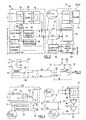
- the Figure 1 schematically illustrates two sets according to the state of the art, each comprising a power supply unit and a device connected together, typically, by a double cord.
- Each set consists of a power supply unit 10 combined low voltage power supply / PLC module, connected by a cord 12 to a socket 14 of the power line (usually 230 V - 50 Hz).
- the power supply unit 10 is provided with a cord 16 serving as a low-voltage power supply conductor (generally +12 V) and a digital data cable 18, for example an Ethernet cable, these two cords 16, 18 being connected to equipment 20 or 26.
- the equipment 20 is for example a multi-function ADSL box connected to a computer 22 and to a telephone jack 24 (for ADSL interfacing), and the equipment 26 is a TV box connected to a television 28. Thanks to the integrated CPL modules to the sector blocks 10, it is possible to exchange data between the equipment 20 placed near the telephone jack 24 and the equipment 26 placed near the television 28.
- the object of the invention is, as illustrated Figure 2 , to eliminate the cable 18 specific to the transmission of digital data between the power supply unit 10 and the equipment 20 or 26, by passing all the information necessary for the implementation of the CPL technique by the only driver of the low voltage power supply 16 of equipment 20 or 26.
- the Figure 3 illustrates in block diagram form the various circuits of the mains unit 10 and those designated 30, which are integrated in the equipment 20, 26 and which are specific to the implementation of the invention.
- the mains unit 10 comprises a switching AC / DC converter 32 (integrating upstream a low-pass filter 33 to prevent the high frequencies generated by the converter from disturbing the CPL signals) making it possible to transform the AC voltage 230 V - 50 Hz. of the sector in a stabilized DC voltage +12 V. This DC voltage is applied to the low-voltage conductor 16 of the remote equipment 20, 26.
- the coupling between the converter 32 and the low-voltage conductor 16 is via a low-pass filter 34 consisting of a power inductance dimensioned so as to be able to withstand the output current in the low-voltage conductor (of several amperes, typically of the order of 4 A), ensuring that the power supply does not have a low impedance at high frequencies, which would attenuate the PLC signals.
- a low-pass filter 34 consisting of a power inductance dimensioned so as to be able to withstand the output current in the low-voltage conductor (of several amperes, typically of the order of 4 A), ensuring that the power supply does not have a low impedance at high frequencies, which would attenuate the PLC signals.
- the mains unit 10 also comprises an additional circuit 36 for detecting the signal ZC (detection of zero crossing), connected to the AC mains input, and an oscillator 38 which generates a sine wave at a frequency located outside the band. frequency of the PLC signals, for example a 500 kHz sine wave oscillator.
- the circuit 36 drives the oscillator 38 so as to modulate at the rhythm of the 50 Hz sector the sine wave 500 kHz, preferably an "all-or-nothing" modulation (OOK modulation, On-Off Keying).
- the modulated signal resulting at the output of the oscillator 38 is applied to the low-voltage conductor 16 via a coupling circuit 40 adapted to the frequency of the sinusoidal oscillator (coupling around the frequency of 500 kHz).
- the power supply unit 10 also comprises a CPL coupling circuit 42, connected at the input to the power line and at the output to the low-voltage conductor 16 downstream of the low-pass filter 34, so that the load presents at the high frequencies an impedance sufficiently high in order not to attenuate CPL signals in the 2-30 MHz band.
- the Figure 4 illustrates the occupation of the frequency spectrum of the various signals present on the low-voltage conductor 16.
- the DC component generated by the converter 32 and outputted from the low-pass filter 34 there is the 2-30 MHz band of the signals digital CPL present on the power line and transferred to the low-voltage conductor by the coupling circuit 2-30 MHz 42.
- the spectrum is also occupied by the carrier 500 kHz generated at the output of the oscillator 38, modulated by the detection signal ZC and applied to the conductor 16 by the coupling circuit 40.
- the frequency of the oscillator 38 (here, 500 kHz) is chosen to be outside the frequency band CPL (here 2-30 MHz) , and with a sufficient distance to avoid in particular that the possible harmonics of the carrier 500 kHz do not disturb the signals located in this band CPL.
- the low-voltage conductor 16 supplies the load 44 at +12 V DC with, according to the usual constraints, a minimum of 50 Hz residual ripple: in fact, when the equipment comprises, for example a hard drive for a DVR, excessive ripple would prevent proper operation of the hard drive, so it is important to master this setting perfectly.
- the circuit 46 for modulation / demodulation CPL comprises a TX / RX input / output connected to the CPL coupling circuit 52, itself directly connected to the low-voltage conductor 16, as well as an Ethernet input / output connected to the internal digital circuits of the circuit.
- This input / output can be conveyed by any type of bus supporting Ethernet such as Media Independent Interface ( MII ), Serial Media Interface ( SMI ), Reduced Gigabit Media Independent Interface ( RGMII ), and so on. so as to do without the transformer usually used and thus reduce the cost of the product.
- MII Media Independent Interface
- SMI Serial Media Interface
- RGMII Reduced Gigabit Media Independent Interface
- the CPL modulation / demodulation circuit 46 also receives an input signal ZC at the mains frequency for the synchronization and sequencing of the modulation and demodulation of the digital data. This signal ZC is extracted by the circuit 50 which is directly connected as input to the low-voltage conductor 16.
- the Figure 5 illustrates the circuits CPL coupling 42 and 52, respectively arranged in the sector block 10 and in the circuit 30 of the equipment 20,26.
- the CPL signal in the 2-30 MHz band is carried by the low-voltage feeder 16 of the equipment, bidirectionally.
- the circuit 42 comprises a transformer 54 providing the necessary insulation between the high voltage of the mains line and the low voltage of the conductor 16.
- This transformer 54 may be a transformer with two windings, alternately coupled to the conductor low voltage supply 16 by two connecting capacitors 56, 58.
- the circuit 52 comprises an isolation transformer 60 comprising three windings, likewise alternatively coupled to the low-voltage conductor 16 by the intermediate capacitors 62, 64.
- the additional circuit 36 may in particular implement an optocoupler 66 for effecting the isolation between the high voltage of the sector and the low voltage of the logic and analog circuits for generating the modulated signals. More precisely, the diode 68 passes only the positive alternation of the sinusoid of the mains voltage, and a divider bridge 70, 72 lowers the voltage to a value compatible with the LED of the optocoupler 66, the resistor 72 being chosen so as not to exceed the maximum allowed reverse voltage across this LED.
- a square signal 74 which controls in all or nothing (amplitude modulation OOK 0-100%) is recovered a sinusoidal oscillator 38 of frequency 500 kHz, whose output signal (500 kHz 50 Hz modulated) is applied to the low-voltage conductor 16 via the link capacitors 76 and 78 of the coupling circuit 40.
- the synchronization circuit 50 for extracting the 50 Hz pulses from the modulated 500 kHz signal comprises link capacitors 80, 82 serving to eliminate the DC component (+12 V) present on the conductor. 16.
- the residual AC signal is applied to a bandpass filter 84 centered on the 500 kHz band, then amplified by the amplifier 86 and applied to a comparator (threshold amplifier) 88 providing a shaping and delivering in accordance with FIG. output signal ZC of zero crossing detection.
- This signal ZC is in the form of a square signal at the mains frequency, identical to the signal 74 which was obtained at the output of the additional circuit 36 of the mains unit, with however a constant phase shift which can be compensated by material means or software during decoding or coding of CPL data by circuit 46.
- the fact of deporting the CPL modulation / demodulation circuits in the equipment makes it possible to reduce the size of the mains unit 10 (i) on the one hand because of the suppression of this circuit CPL, and (ii) d on the other hand and above all, because of the reduction of thermal stresses.
- the CPL circuit no longer undergoes heating of the converter of the mains unit. Since in addition it is placed in the equipment, it has a larger volume to dissipate the heat it produces, so that it It is much easier to ensure the proper cooling of the corresponding digital circuits, thus increasing their reliability and their lifetime.
- the power supply unit may in particular be provided for this purpose with a pushbutton 90 ( Figure 1 ) allowing the triggering of an "all or nothing" modulation during periods when the PLC is not used.
- This "all or nothing” modulation is an OOK (On-Off Keying) modulation, "all” meaning that the control signal 74 is generated by the circuit 36 and therefore activates the oscillator 38, and “nothing” signifying that the signal 74 is not generated, thereby inhibiting the oscillator 38. It makes it possible, for example, to transmit to the equipment information contained in a memory 92 of the sector block (such as serial number, version, etc.). via the power supply conductor 16, or supervision signals of the power supply unit such as: temperature alarm, overvoltage detected, various malfunctions, etc.
- This transmission of low bit rate information between the power supply unit and the equipment is performed during the "silent periods" of the CPL data, ie the periods when none of this digital data is transmitted on the driver 16.
- This function can in particular be used at power-up, for example by pressing the button 90 for the association of the CPL boxes or the reading of the memory 92.
Landscapes
- Engineering & Computer Science (AREA)
- Power Engineering (AREA)
- Computer Networks & Wireless Communication (AREA)
- Signal Processing (AREA)
- Cable Transmission Systems, Equalization Of Radio And Reduction Of Echo (AREA)
- Dc Digital Transmission (AREA)
Claims (10)
- Einheit, die eine Stromnetzkommunikation(PLC)-Übertragungstechnik von Daten anwendet, die auf einer Netzleitung transportiert werden, die Folgendes enthält:- eine Ausrüstung (20, 26), die digitale PLC-Daten verarbeiten kann, die auf der Netzleitung empfangen oder gesendet werden;- ein von der Ausrüstung getrenntes Netzanschlussgerät (10), das einen getakteten Wandler (32) aufweist, der eine Speisegleichspannung ausgehend von der Spannung der Netzleitung erzeugen kann; und- einen Niederspannungsspeiseleiter (16), der das Netzanschlussgerät mit der Ausrüstung verbindet, um an diese die vom fernen Netzanschlussgerät erzeugte Speisegleichspannung zu liefern,
wobei die Einheit Folgendes aufweist:- einen Modulations-/Demodulationsschaltkreis von PLC-Strömen, die von der Netzleitung übertragen werden; und- einen Synchronisationsschaltkreis, der ein Signal auf der Netzfrequenz erzeugt, das an den Eingang des Modulations-/Demodulationsschaltkreises angelegt wird,
wobei diese Einheit im Wesentlichen keine spezifische Verbindung zur Übertragung digitaler Daten zwischen dem Netzanschlussgerät und der Ausrüstung aufweist, wobei diese digitalen Daten mit Hilfe des Niederspannungs-Speiseleiters (16) übertragen werden;
wobei der PLC-Modulations-/Demodulationsschaltkreis (46) und der Synchronisationsschaltkreis (50) in der Ausrüstung (20, 26) angeordnet sind, und
wobei das Netzanschlussgerät (10) einen PLC-Schaltkreis (42) zwischen der Netzleitung und dem Niederspannungsleiter enthält, und die Ausrüstung (20, 26) einen PLC-Kopplungsschaltkreis (52) zwischen dem Niederspannungsleiter und dem PLC-Modulations-/Demodulationsschaltkreis enthält, wobei die Einheit dadurch gekennzeichnet ist, dass:- im Netzanschlussgerät (10) vorgesehen ist:• ein zusätzlicher Schaltkreis (36), der am Eingang mit der Netzleitung gekoppelt ist und am Ausgang ein Steuersignal (74) auf der Netzfrequenz liefert; und• ein Oszillator (38), der eine Sinuswelle auf einer Frequenz erzeugt, die höher ist als die Netzfrequenz und sich außerhalb des Modulations-/Demodulations-Frequenzbands der PLC-Signale befindet, wobei diese Welle durch das vom zusätzlichen Schaltkreis (36) gelieferte Steuersignal (74) moduliert wird, und wobei der Ausgang des Oszillators so mit dem Niederspannungsleiter gekoppelt ist, dass die modulierte Welle in Überlagerung der Versorgungsgleichspannung eingespeist wird; und- der Synchronisationsschaltkreis in der Ausrüstung einen Impulsentnahmeschaltkreis (50) auf der Netzfrequenz enthält, der am Eingang mit dem Niederspannungsleiter gekoppelt ist. - Einheit nach Anspruch 1, bei der der zusätzliche Schaltkreis (36) ein Kopplungsschaltkreis über einen optischen Koppler (66) ist, der zwischen die Netzleitung und einen Modulationseingang des Oszillators (38) eingefügt ist.
- Einheit nach Anspruch 1, bei der im Netzanschlussgerät (10) ein Tiefpassfilter (34) zwischen dem Ausgang des getakteten Wandlers und dem Niederspannungsleiter vorgesehen ist, und in der Ausrüstung (20, 26) ein Tiefpassfilter (48) zwischen dem Niederspannungsleiter und den Schaltkreisen der Ausrüstung vorgesehen ist, die mit der vom getakteten Wandler erzeugten Gleichspannung gespeist werden sollen.
- Einheit nach Anspruch 1, bei der der Impulsentnahmeschaltkreis (50) ein Bandpassfilter (84) enthält, das auf die Frequenz der Sinuswelle zentriert, am Eingang mit dem Niederspannungsleiter gekoppelt ist, und dessen Ausgang an den Eingang eines Schwellenkomparators (88) angelegt wird, der am Ausgang ein Impulssignal (ZC) auf der Netzfrequenz liefert, das an den Eingang des PLC-Modulations-/Demodulationsschaltkreises (46) angelegt wird.
- Einheit nach Anspruch 1, bei der der Synchronisationsschaltkreis außerdem Hardware- oder Softwareeinrichtungen zur Kompensation der Phasenverschiebung des Signals auf der Netzfrequenz, das von dem Impulsentnahmeschaltkreis (50) geliefert wird, bezüglich der Wechselspannung der Netzleitung enthält.
- Einheit nach Anspruch 1, bei der die Frequenz der Sinuswelle im 500 kHz-Band liegt, während die Modulations-/Demodulationsfrequenzen der PLC-Signale im 2-30 MHz-Band liegen.
- Einheit nach Anspruch 1, die außerdem Einrichtungen zur Übertragung von Informationen mit niedriger Übertragungsrate auf der Niederspannungsleitung enthält, bei denen:- das Netzanschlussgerät (10) einen Schaltkreis enthält, um eine Ein/Aus-Modulation des Steuerungsignals auf der Netzfrequenz abhängig von den zu übertragenden Informationen durchzuführen; und- die Ausrüstung (20, 26) Decodiereinrichtungen enthält, um die zu übertragenden Informationen ausgehend von dem am Ausgang vom Impulsentnahmeschaltkreis gelieferten Signal zu entnehmen, der am Eingang mit dem Niederspannungsleiter gekoppelt ist.
- Einheit nach Anspruch 7, bei der das Netzanschlussgerät (10) außerdem einen Drücker (90) zur Aktivierung des Ein/Aus-Modulationsschaltkreises enthält, um die Übertragung der Informationen zu initiieren, die in einem Speicher (92) des Netzanschlussgeräts enthalten sind.
- Netzanschlussgerät (10), das an eine Einheit nach einem der Ansprüche 1 bis 8 angepasst ist, das Folgendes enthält:- einen getakteten Wandler (32), der eine Speisegleichspannung ausgehend von der Spannung der Netzleitung erzeugen kann;- einen PLC-Schaltkreis (42) zwischen der Netzleitung und dem Niederspannungsspeiseleiter, und- einen zusätzlichen Schaltkreis (36), der am Eingang mit der Netzleitung gekoppelt ist und am Ausgang ein Steuersignal (74) auf der Netzfrequenz liefert; und- einen Oszillator (38), der eine Sinuswelle auf einer Frequenz erzeugt, die höher ist als die Netzfrequenz und sich außerhalb des Modulations-/Demodulations-Frequenzbands der PLC-Signale befindet, wobei diese Welle von dem vom zusätzlichen Schaltkreis gelieferten Steuersignal (74) moduliert wird, und der Ausgang des Oszillators so mit dem Niederspannungsleiter gekoppelt ist, dass die modulierte Welle in Überlagerung der Versorgungsgleichspannung eingespeist wird.
- Ausrüstung (20, 26), die an eine Einheit nach einem der Ansprüche 1 bis 8 angepasst ist und Folgendes enthält:- einen Schaltkreis (46) zur Modulation/Demodulation von PLC-Strömen, die von der Netzleitung transportiert werden;- einen PLC-Kopplungsschaltkreis (52) zwischen dem Niederspannungsspeiseleiter und dem PLC-Modulations-/Demodulationsschaltkreis; und- einen Synchronisationsschaltkreis, der einen Impulsentnahmeschaltkreis (50) auf der Netzfrequenz enthält, der am Eingang mit dem Niederspannungsleiter gekoppelt ist und am Ausgang ein Signal auf der Netzfrequenz erzeugt, das an den Eingang des Modulations-/Demodulationsschaltkreises angelegt wird.
Applications Claiming Priority (1)
| Application Number | Priority Date | Filing Date | Title |
|---|---|---|---|
| FR1055395A FR2962277B1 (fr) | 2010-07-02 | 2010-07-02 | Ensemble equipement/bloc secteur a transmission de donnees par courants porteurs en ligne cpl |
Publications (2)
| Publication Number | Publication Date |
|---|---|
| EP2403151A1 EP2403151A1 (de) | 2012-01-04 |
| EP2403151B1 true EP2403151B1 (de) | 2012-10-03 |
Family
ID=43501500
Family Applications (1)
| Application Number | Title | Priority Date | Filing Date |
|---|---|---|---|
| EP20110171184 Active EP2403151B1 (de) | 2010-07-02 | 2011-06-23 | Ausrüstungseinheit/sektorblock mit cpl-online-datenübertragung durch trägerstrom |
Country Status (3)
| Country | Link |
|---|---|
| EP (1) | EP2403151B1 (de) |
| ES (1) | ES2397092T3 (de) |
| FR (1) | FR2962277B1 (de) |
Families Citing this family (3)
| Publication number | Priority date | Publication date | Assignee | Title |
|---|---|---|---|---|
| FR3053861B1 (fr) | 2016-07-07 | 2019-08-09 | Safran Electrical & Power | Procede et systeme de communication pour des modules interconnectes par courants porteurs en ligne |
| US12192028B2 (en) * | 2021-05-19 | 2025-01-07 | Focus Universal Inc. | System and method for a smart home system |
| KR102797666B1 (ko) * | 2024-07-30 | 2025-04-22 | (주) 선일일렉콤 | 주파수 기반 ook를 통한 전력선 통신 방법 및 그 장치 |
Family Cites Families (3)
| Publication number | Priority date | Publication date | Assignee | Title |
|---|---|---|---|---|
| DE2903860C2 (de) * | 1979-02-01 | 1983-10-27 | Siemens AG, 1000 Berlin und 8000 München | Einrichtung zur Gleichstromversorgung eines Verbrauchers und zur gleichzeitigen Informationsübertragung über ein Aderpaar |
| CA1226914A (en) * | 1984-01-26 | 1987-09-15 | The University Of British Columbia | Modem for pseudo noise communication on a.c. lines |
| JP2003258690A (ja) * | 2002-03-05 | 2003-09-12 | Alps Electric Co Ltd | 電力搬送用モデム |
-
2010
- 2010-07-02 FR FR1055395A patent/FR2962277B1/fr not_active Expired - Fee Related
-
2011
- 2011-06-23 EP EP20110171184 patent/EP2403151B1/de active Active
- 2011-06-23 ES ES11171184T patent/ES2397092T3/es active Active
Also Published As
| Publication number | Publication date |
|---|---|
| EP2403151A1 (de) | 2012-01-04 |
| ES2397092T3 (es) | 2013-03-04 |
| FR2962277A1 (fr) | 2012-01-06 |
| FR2962277B1 (fr) | 2012-08-17 |
Similar Documents
| Publication | Publication Date | Title |
|---|---|---|
| EP2400668B1 (de) | Ausrüstungseinheit/Sektorblock mit CPL-Online-Datenübertragung durch Trägerstrom | |
| CA2603867C (en) | Network interface device with a remote power source | |
| JP6886251B2 (ja) | 電力線通信及びパワー・オーバー・イーサネット用カプラ | |
| JP5845430B2 (ja) | 通信装置およびその給電方法および給電システム | |
| US7450000B2 (en) | Power line communications device and method | |
| EP1925097B1 (de) | Stromleitungs-kommunikationsvorrichtung | |
| US8548035B2 (en) | Powerline communicator (PLC) modem employing an analog magnetic transducer | |
| US20030068033A1 (en) | Telecommunications gateway and method | |
| US20100049994A1 (en) | Universal Ethernet Power Adapter | |
| GB2485781A (en) | Using no more than four wires to convey a DC voltage, a signal representing the timing of a mains power supply, and a broadband data signal | |
| JP4814360B2 (ja) | イーサネット接続ビデオ | |
| EP2540012A1 (de) | System und verfahren für ein teilnehmergesteuertes netzwerkelement | |
| CN102801445B (zh) | 高性能电力线通信群系统 | |
| EP2403151B1 (de) | Ausrüstungseinheit/sektorblock mit cpl-online-datenübertragung durch trägerstrom | |
| TW200910797A (en) | Power mains data transfer system | |
| EP2368329B1 (de) | Elektronische vorrichtung zur netzleitungsübertragung | |
| EP2803167B1 (de) | Vorrichtung zum verbinden zweier geräteteile über eine ethernetverbindung und andockstation für einen solchen geräteteil | |
| EP2494702B1 (de) | Vorrichtung für die verwendung in einem stromleitungskommunikationssystem, stromleitungskommunikationssysteme und stromleitungskommunikationsverfahren | |
| EP1665759A1 (de) | System und einrichtung zur fernbestromung einer datenverarbeitungseinrichtung | |
| EP2820766B1 (de) | Modulations-demodulations-vorrichtung zum senden und empfangen von daten auf einer hochspannungsleitung | |
| EP3676441B1 (de) | Bügelsystem, das eine bidirektionelle datenübertragung zwischen basis und bügeleisen umfasst | |
| HK40035803A (en) | Device and method for a subscriber powered network element | |
| FR2879329A1 (fr) | Systeme de telealimentation permanente d'un equipement dans une installation electrique | |
| EP2219297A1 (de) | Elektrisch betriebene Kommunikationsvorrichtung | |
| EP1323245A2 (de) | Leistungsversorgungsarchitektur für stromversorgungsnetz |
Legal Events
| Date | Code | Title | Description |
|---|---|---|---|
| 17P | Request for examination filed |
Effective date: 20110623 |
|
| AK | Designated contracting states |
Kind code of ref document: A1 Designated state(s): AL AT BE BG CH CY CZ DE DK EE ES FI FR GB GR HR HU IE IS IT LI LT LU LV MC MK MT NL NO PL PT RO RS SE SI SK SM TR |
|
| AX | Request for extension of the european patent |
Extension state: BA ME |
|
| PUAI | Public reference made under article 153(3) epc to a published international application that has entered the european phase |
Free format text: ORIGINAL CODE: 0009012 |
|
| RIC1 | Information provided on ipc code assigned before grant |
Ipc: H04B 3/54 20060101AFI20120214BHEP |
|
| GRAP | Despatch of communication of intention to grant a patent |
Free format text: ORIGINAL CODE: EPIDOSNIGR1 |
|
| RTI1 | Title (correction) |
Free format text: DEVICE/POWER ADAPTER ASSEMBLY WITH DATA TRANSMISSION BY POWERLINE COMMUNICATION PLC |
|
| GRAS | Grant fee paid |
Free format text: ORIGINAL CODE: EPIDOSNIGR3 |
|
| GRAA | (expected) grant |
Free format text: ORIGINAL CODE: 0009210 |
|
| AK | Designated contracting states |
Kind code of ref document: B1 Designated state(s): AL AT BE BG CH CY CZ DE DK EE ES FI FR GB GR HR HU IE IS IT LI LT LU LV MC MK MT NL NO PL PT RO RS SE SI SK SM TR |
|
| REG | Reference to a national code |
Ref country code: GB Ref legal event code: FG4D Free format text: NOT ENGLISH |
|
| REG | Reference to a national code |
Ref country code: AT Ref legal event code: REF Ref document number: 578388 Country of ref document: AT Kind code of ref document: T Effective date: 20121015 Ref country code: CH Ref legal event code: EP |
|
| REG | Reference to a national code |
Ref country code: IE Ref legal event code: FG4D Free format text: LANGUAGE OF EP DOCUMENT: FRENCH |
|
| REG | Reference to a national code |
Ref country code: DE Ref legal event code: R096 Ref document number: 602011000290 Country of ref document: DE Effective date: 20121129 |
|
| REG | Reference to a national code |
Ref country code: NL Ref legal event code: T3 |
|
| REG | Reference to a national code |
Ref country code: AT Ref legal event code: MK05 Ref document number: 578388 Country of ref document: AT Kind code of ref document: T Effective date: 20121003 |
|
| PG25 | Lapsed in a contracting state [announced via postgrant information from national office to epo] |
Ref country code: SI Free format text: LAPSE BECAUSE OF FAILURE TO SUBMIT A TRANSLATION OF THE DESCRIPTION OR TO PAY THE FEE WITHIN THE PRESCRIBED TIME-LIMIT Effective date: 20121003 |
|
| REG | Reference to a national code |
Ref country code: ES Ref legal event code: FG2A Ref document number: 2397092 Country of ref document: ES Kind code of ref document: T3 Effective date: 20130304 |
|
| REG | Reference to a national code |
Ref country code: LT Ref legal event code: MG4D |
|
| PG25 | Lapsed in a contracting state [announced via postgrant information from national office to epo] |
Ref country code: NO Free format text: LAPSE BECAUSE OF FAILURE TO SUBMIT A TRANSLATION OF THE DESCRIPTION OR TO PAY THE FEE WITHIN THE PRESCRIBED TIME-LIMIT Effective date: 20130103 Ref country code: HR Free format text: LAPSE BECAUSE OF FAILURE TO SUBMIT A TRANSLATION OF THE DESCRIPTION OR TO PAY THE FEE WITHIN THE PRESCRIBED TIME-LIMIT Effective date: 20121003 Ref country code: LT Free format text: LAPSE BECAUSE OF FAILURE TO SUBMIT A TRANSLATION OF THE DESCRIPTION OR TO PAY THE FEE WITHIN THE PRESCRIBED TIME-LIMIT Effective date: 20121003 Ref country code: FI Free format text: LAPSE BECAUSE OF FAILURE TO SUBMIT A TRANSLATION OF THE DESCRIPTION OR TO PAY THE FEE WITHIN THE PRESCRIBED TIME-LIMIT Effective date: 20121003 Ref country code: SE Free format text: LAPSE BECAUSE OF FAILURE TO SUBMIT A TRANSLATION OF THE DESCRIPTION OR TO PAY THE FEE WITHIN THE PRESCRIBED TIME-LIMIT Effective date: 20121003 Ref country code: IS Free format text: LAPSE BECAUSE OF FAILURE TO SUBMIT A TRANSLATION OF THE DESCRIPTION OR TO PAY THE FEE WITHIN THE PRESCRIBED TIME-LIMIT Effective date: 20130203 |
|
| PG25 | Lapsed in a contracting state [announced via postgrant information from national office to epo] |
Ref country code: GR Free format text: LAPSE BECAUSE OF FAILURE TO SUBMIT A TRANSLATION OF THE DESCRIPTION OR TO PAY THE FEE WITHIN THE PRESCRIBED TIME-LIMIT Effective date: 20130104 Ref country code: LV Free format text: LAPSE BECAUSE OF FAILURE TO SUBMIT A TRANSLATION OF THE DESCRIPTION OR TO PAY THE FEE WITHIN THE PRESCRIBED TIME-LIMIT Effective date: 20121003 Ref country code: PT Free format text: LAPSE BECAUSE OF FAILURE TO SUBMIT A TRANSLATION OF THE DESCRIPTION OR TO PAY THE FEE WITHIN THE PRESCRIBED TIME-LIMIT Effective date: 20130204 Ref country code: PL Free format text: LAPSE BECAUSE OF FAILURE TO SUBMIT A TRANSLATION OF THE DESCRIPTION OR TO PAY THE FEE WITHIN THE PRESCRIBED TIME-LIMIT Effective date: 20121003 |
|
| PG25 | Lapsed in a contracting state [announced via postgrant information from national office to epo] |
Ref country code: AT Free format text: LAPSE BECAUSE OF FAILURE TO SUBMIT A TRANSLATION OF THE DESCRIPTION OR TO PAY THE FEE WITHIN THE PRESCRIBED TIME-LIMIT Effective date: 20121003 |
|
| PG25 | Lapsed in a contracting state [announced via postgrant information from national office to epo] |
Ref country code: DK Free format text: LAPSE BECAUSE OF FAILURE TO SUBMIT A TRANSLATION OF THE DESCRIPTION OR TO PAY THE FEE WITHIN THE PRESCRIBED TIME-LIMIT Effective date: 20121003 Ref country code: EE Free format text: LAPSE BECAUSE OF FAILURE TO SUBMIT A TRANSLATION OF THE DESCRIPTION OR TO PAY THE FEE WITHIN THE PRESCRIBED TIME-LIMIT Effective date: 20121003 Ref country code: CZ Free format text: LAPSE BECAUSE OF FAILURE TO SUBMIT A TRANSLATION OF THE DESCRIPTION OR TO PAY THE FEE WITHIN THE PRESCRIBED TIME-LIMIT Effective date: 20121003 Ref country code: RS Free format text: LAPSE BECAUSE OF FAILURE TO SUBMIT A TRANSLATION OF THE DESCRIPTION OR TO PAY THE FEE WITHIN THE PRESCRIBED TIME-LIMIT Effective date: 20121003 Ref country code: SK Free format text: LAPSE BECAUSE OF FAILURE TO SUBMIT A TRANSLATION OF THE DESCRIPTION OR TO PAY THE FEE WITHIN THE PRESCRIBED TIME-LIMIT Effective date: 20121003 Ref country code: BG Free format text: LAPSE BECAUSE OF FAILURE TO SUBMIT A TRANSLATION OF THE DESCRIPTION OR TO PAY THE FEE WITHIN THE PRESCRIBED TIME-LIMIT Effective date: 20130103 |
|
| PLBE | No opposition filed within time limit |
Free format text: ORIGINAL CODE: 0009261 |
|
| STAA | Information on the status of an ep patent application or granted ep patent |
Free format text: STATUS: NO OPPOSITION FILED WITHIN TIME LIMIT |
|
| PG25 | Lapsed in a contracting state [announced via postgrant information from national office to epo] |
Ref country code: RO Free format text: LAPSE BECAUSE OF FAILURE TO SUBMIT A TRANSLATION OF THE DESCRIPTION OR TO PAY THE FEE WITHIN THE PRESCRIBED TIME-LIMIT Effective date: 20121003 |
|
| 26N | No opposition filed |
Effective date: 20130704 |
|
| REG | Reference to a national code |
Ref country code: DE Ref legal event code: R097 Ref document number: 602011000290 Country of ref document: DE Effective date: 20130704 |
|
| PG25 | Lapsed in a contracting state [announced via postgrant information from national office to epo] |
Ref country code: CY Free format text: LAPSE BECAUSE OF FAILURE TO SUBMIT A TRANSLATION OF THE DESCRIPTION OR TO PAY THE FEE WITHIN THE PRESCRIBED TIME-LIMIT Effective date: 20121003 |
|
| PG25 | Lapsed in a contracting state [announced via postgrant information from national office to epo] |
Ref country code: MC Free format text: LAPSE BECAUSE OF FAILURE TO SUBMIT A TRANSLATION OF THE DESCRIPTION OR TO PAY THE FEE WITHIN THE PRESCRIBED TIME-LIMIT Effective date: 20121003 |
|
| REG | Reference to a national code |
Ref country code: IE Ref legal event code: MM4A |
|
| PG25 | Lapsed in a contracting state [announced via postgrant information from national office to epo] |
Ref country code: IE Free format text: LAPSE BECAUSE OF NON-PAYMENT OF DUE FEES Effective date: 20130623 |
|
| REG | Reference to a national code |
Ref country code: CH Ref legal event code: PL |
|
| PG25 | Lapsed in a contracting state [announced via postgrant information from national office to epo] |
Ref country code: MT Free format text: LAPSE BECAUSE OF FAILURE TO SUBMIT A TRANSLATION OF THE DESCRIPTION OR TO PAY THE FEE WITHIN THE PRESCRIBED TIME-LIMIT Effective date: 20121003 |
|
| PG25 | Lapsed in a contracting state [announced via postgrant information from national office to epo] |
Ref country code: CH Free format text: LAPSE BECAUSE OF NON-PAYMENT OF DUE FEES Effective date: 20140630 Ref country code: LI Free format text: LAPSE BECAUSE OF NON-PAYMENT OF DUE FEES Effective date: 20140630 |
|
| REG | Reference to a national code |
Ref country code: CH Ref legal event code: AECN Free format text: LE BREVET A ETE REACTIVE SELON LA DEMANDE DE POURSUITE DE LA PROCEDURE DU 21.04.2015 Ref country code: CH Ref legal event code: NV Representative=s name: KIRKER AND CIE S.A., CH |
|
| PG25 | Lapsed in a contracting state [announced via postgrant information from national office to epo] |
Ref country code: SM Free format text: LAPSE BECAUSE OF FAILURE TO SUBMIT A TRANSLATION OF THE DESCRIPTION OR TO PAY THE FEE WITHIN THE PRESCRIBED TIME-LIMIT Effective date: 20121003 |
|
| PG25 | Lapsed in a contracting state [announced via postgrant information from national office to epo] |
Ref country code: TR Free format text: LAPSE BECAUSE OF FAILURE TO SUBMIT A TRANSLATION OF THE DESCRIPTION OR TO PAY THE FEE WITHIN THE PRESCRIBED TIME-LIMIT Effective date: 20121003 |
|
| PG25 | Lapsed in a contracting state [announced via postgrant information from national office to epo] |
Ref country code: HU Free format text: LAPSE BECAUSE OF FAILURE TO SUBMIT A TRANSLATION OF THE DESCRIPTION OR TO PAY THE FEE WITHIN THE PRESCRIBED TIME-LIMIT; INVALID AB INITIO Effective date: 20110623 Ref country code: MK Free format text: LAPSE BECAUSE OF FAILURE TO SUBMIT A TRANSLATION OF THE DESCRIPTION OR TO PAY THE FEE WITHIN THE PRESCRIBED TIME-LIMIT Effective date: 20121003 Ref country code: LU Free format text: LAPSE BECAUSE OF NON-PAYMENT OF DUE FEES Effective date: 20130623 |
|
| PGRI | Patent reinstated in contracting state [announced from national office to epo] |
Ref country code: CH Effective date: 20150421 Ref country code: LI Effective date: 20150421 |
|
| REG | Reference to a national code |
Ref country code: FR Ref legal event code: PLFP Year of fee payment: 6 |
|
| REG | Reference to a national code |
Ref country code: FR Ref legal event code: PLFP Year of fee payment: 7 |
|
| REG | Reference to a national code |
Ref country code: FR Ref legal event code: PLFP Year of fee payment: 8 |
|
| PG25 | Lapsed in a contracting state [announced via postgrant information from national office to epo] |
Ref country code: AL Free format text: LAPSE BECAUSE OF FAILURE TO SUBMIT A TRANSLATION OF THE DESCRIPTION OR TO PAY THE FEE WITHIN THE PRESCRIBED TIME-LIMIT Effective date: 20121003 |
|
| PGFP | Annual fee paid to national office [announced via postgrant information from national office to epo] |
Ref country code: DE Payment date: 20250618 Year of fee payment: 15 |
|
| PGFP | Annual fee paid to national office [announced via postgrant information from national office to epo] |
Ref country code: GB Payment date: 20250620 Year of fee payment: 15 |
|
| PGFP | Annual fee paid to national office [announced via postgrant information from national office to epo] |
Ref country code: NL Payment date: 20250618 Year of fee payment: 15 Ref country code: BE Payment date: 20250617 Year of fee payment: 15 |
|
| PGFP | Annual fee paid to national office [announced via postgrant information from national office to epo] |
Ref country code: FR Payment date: 20250604 Year of fee payment: 15 |
|
| PGFP | Annual fee paid to national office [announced via postgrant information from national office to epo] |
Ref country code: ES Payment date: 20250718 Year of fee payment: 15 |
|
| PGFP | Annual fee paid to national office [announced via postgrant information from national office to epo] |
Ref country code: IT Payment date: 20250630 Year of fee payment: 15 |
|
| PGFP | Annual fee paid to national office [announced via postgrant information from national office to epo] |
Ref country code: CH Payment date: 20250701 Year of fee payment: 15 |