EP2406164B1 - Système d'ascenseur avec support de rail de guidage - Google Patents
Système d'ascenseur avec support de rail de guidage Download PDFInfo
- Publication number
- EP2406164B1 EP2406164B1 EP09841627.4A EP09841627A EP2406164B1 EP 2406164 B1 EP2406164 B1 EP 2406164B1 EP 09841627 A EP09841627 A EP 09841627A EP 2406164 B1 EP2406164 B1 EP 2406164B1
- Authority
- EP
- European Patent Office
- Prior art keywords
- guide rail
- base
- bracket
- assembly
- rail support
- Prior art date
- Legal status (The legal status is an assumption and is not a legal conclusion. Google has not performed a legal analysis and makes no representation as to the accuracy of the status listed.)
- Not-in-force
Links
- 239000002184 metal Substances 0.000 claims description 10
- 239000000463 material Substances 0.000 description 7
- 238000009434 installation Methods 0.000 description 5
- 238000011900 installation process Methods 0.000 description 3
- 238000005452 bending Methods 0.000 description 2
- 238000010276 construction Methods 0.000 description 1
- 238000005259 measurement Methods 0.000 description 1
- 238000012986 modification Methods 0.000 description 1
- 230000004048 modification Effects 0.000 description 1
- 230000002787 reinforcement Effects 0.000 description 1
- 230000003014 reinforcing effect Effects 0.000 description 1
- 230000000087 stabilizing effect Effects 0.000 description 1
Images



Classifications
-
- B—PERFORMING OPERATIONS; TRANSPORTING
- B66—HOISTING; LIFTING; HAULING
- B66B—ELEVATORS; ESCALATORS OR MOVING WALKWAYS
- B66B7/00—Other common features of elevators
- B66B7/02—Guideways; Guides
- B66B7/023—Mounting means therefor
- B66B7/024—Lateral supports
-
- B—PERFORMING OPERATIONS; TRANSPORTING
- B66—HOISTING; LIFTING; HAULING
- B66B—ELEVATORS; ESCALATORS OR MOVING WALKWAYS
- B66B13/00—Doors, gates, or other apparatus controlling access to, or exit from, cages or lift well landings
- B66B13/30—Constructional features of doors or gates
-
- B—PERFORMING OPERATIONS; TRANSPORTING
- B66—HOISTING; LIFTING; HAULING
- B66B—ELEVATORS; ESCALATORS OR MOVING WALKWAYS
- B66B7/00—Other common features of elevators
- B66B7/02—Guideways; Guides
- B66B7/023—Mounting means therefor
Definitions
- Elevator systems are well known and in widespread use. There are various configurations of elevator systems. In many cases, an elevator car is associated with a counterweight and the two move in a coordinated fashion within a hoistway. The elevator car and counterweight each follow guide rails as they move within the hoistway.
- a guide rail installation process is typically time-consuming and labor- intensive.
- bracket components used for securing the guide rails in desired positions within a hoistway.
- the alignment of the guide rails throughout the hoistway must be ensured to achieve proper ride quality.
- An exemplary door frame assembly that is useful in an elevator system includes a plurality of door frame members including a header, a sill and a plurality of jambs.
- the door frame members are configured to be secured into a desired position along a hoistway.
- At least one guide rail bracket is supported by at least one of the door frame members.
- the guide rail bracket is moveable relative to the door frame member between a handling position in which the guide rail bracket is generally parallel to at least one of the header or the sill and a deployed position in which the guide rail bracket is generally perpendicular to the at least one of the header or sill.
- the guide rail bracket base may have a length that is longer than any other portion of the guide rail bracket. Further, the guide rail bracket may be pivotally moveable relative to the at least one of the door frame members.
- the at least one of the door frame members may be spaced a distance from a wall of the hoistway that is perpendicular to the at least one of the header or the sill and the guide rail bracket is supported in a position such that a portion of the guide rail bracket is received against the wall in the deployed position.
- the guide rail bracket may comprise: a car guide rail support arm near a first end of the base, the car guide rail support arm being adapted to secure a corresponding portion of a car guide rail in a desired position within a hoistway; and a plurality of counterweight guide rail support arms between the car guide rail support arm and a second, opposite end of the base, the counterweight guide rail support arms each being adapted to secure a corresponding portion of a counterweight guide rail in a desired position within a hoistway.
- the base, the car guide rail support arm and the counterweight guide rail support arms may all be part of a single, integrated structure.
- the car guide rail support arm may comprise three sections of the base near the first end that are bent to be transverse to each other.
- a first one of the sections may extend in a direction away from the base, a second one of the sections may extend from the first one of the sections in a direction parallel to the base and a third one of the sections may extend from the second one of the sections in a direction toward the base.
- the car guide rail support arm may have a rail receiving surface in a first orientation relative to the base and the counterweight guide rail support arms each has a rail receiving surface in a second, different orientation relative to the base.
- the car guide rail support arm rail receiving surface may be parallel to the base surface and the counterweight guide rail support arms rail receiving surfaces are generally perpendicular to the base surface.
- the base may comprise a single metal plate; the car guide rail support arm may comprise a bent portion of the metal plate near the first end; one of the counterweight guide rail support arms may comprise a bent portion of the metal plate near the second end; and another one of the counterweight guide rail support arms may comprise another piece of metal secured to the base plate at a selected distance from the one of the counterweight guide rail support arms.
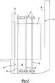
- Figure 1 illustrates selected portions of an elevator system 20 including an elevator car 22 that is moveable along car guide rails 24.
- a counterweight 26 is associated with the elevator car 22 by a roping arrangement (not illustrated) and moves along counterweight guide rails 28 in coordination with movement of the elevator car 22.
- One of the car guide rails 24 and both of the counterweight guide rails 28 are on one lateral side (i.e., not the front side that includes the doors or the oppositely facing back side) of the elevator car 22.
- a plurality of brackets 30 secure those guide rails in their desired positions.
- the elevator car 22 and counterweight 26 are moveable within a hoistway 32 having a front wall 34 (i.e., the wall that includes the door), rear wall 36 and sidewalls 38.
- the brackets 30 are secured to the sidewall 38 on the lateral side of the elevator car selected for positioning the counterweight 26.
- the counterweight guide rails 28 (and, therefore, the counterweight 26) are between the car guide rail 24 and the front wall 34 of the hoistway 32.
- the counterweight 26 has a reduced width compared to conventional counterweight arrangements so that the counterweight 26 and the counterweight guide rails 28 all fit within a front quadrant of the hoistway 32 (i.e., between a mid-point of the wall 38 and the front wall 34). In some examples, only a few brackets 30 are required along the entire length of the hoistway.
- the illustrated example bracket 30 includes a base 40 that is secured in a fixed position parallel to the hoistway wall 38.
- the base 40 is generally planar and has a surface 42 that is received toward and parallel with the hoistway wall 38.
- mounting members 44 facilitate making the connection between the bracket 30 and the hoistway wall 38.
- the surface 42 is received directly against the surface of the hoistway wall 38.
- the example bracket 30 includes support arms for supporting the guide rails in desired vertical and horizontal positions at a selected distance away from the hoistway wall 38 and the other guide rails.
- a car guide rail support arm comprises a plurality of bent sections in this example.
- a first section 46, a second section 48 and a third section 50 of the bracket 30 are bent relative to each other and the base 40.
- the first section 46 and the third section 50 are generally perpendicular to the second section 48 and the surface 42 of the base 40.
- the second section 48 includes a surface against which the car guide rail 24 is received and held in place using clips 52.
- threaded members such as bolts are used to hold the clips 52 in place for securing the corresponding portion of the car guide rail 24 against the car guide rail support arm.
- the car guide rail support arm is near one end 54 of the bracket 30.
- the sections 46, 48 and 50 are established by bending a metal plate into the configuration shown in the illustrations.
- the car guide rail support arm is a part of the same, single piece of material as the base 40.
- Another section 56 of the bracket 30 is generally perpendicular to the surface 42 of the base 40.
- the section 56 establishes a counterweight guide rail support arm.
- One of the counterweight guide rails 28 is received against a surface on the section 56 and held in place by clips 60 and corresponding threaded fasteners.
- the section 56 is established by bending the material of the bracket 30 near the second end 58.
- the illustrated example includes a reinforcing member 62 between the section 56 and the base 40 to maintain a desired alignment between them.
- Another counterweight guide rail support arm 64 is provided between the third section 50 and the section 56 of the bracket 30.
- the counterweight guide rail support arm 64 comprises a separate piece of material secured to the base 40.
- the counterweight guide rail support arm 64 has a portion that is welded to the base 40 of the bracket 30.
- the car guide rail arm surface 48 is parallel to the base 40 and the hoistway wall 38.
- the rail receiving surfaces of the counterweight guide rail support arms 56 and 64 are perpendicular to the base 40 and the hoistway wall 38.
- Utilizing a bracket such as the example bracket 30 facilitates various economies when installing guide rails within an elevator system.
- One feature is that there are less component pieces for an installer to handle during installation.
- the integrated bracket is lighter and easier to install compared to the conventional multiplicity of individual brackets.
- the desired spacing between the guide rails remains consistent along the length of the hoistway, which reduces alignment adjustments. Having a preset distance between the guide rail support arms automatically establishes the spacing of the corresponding portions of the guide rails at the location of each bracket.
- a single alignment of the car guide rail (or one of the counterweight rails) provides placement of all three guide rails because the bracket 30 controls the position of all three based on the position of at least one of the three. Having the bracket 30 pre-dimensioned and accurately manufactured, therefore simplifies the installation process.
- the bracket 30 will have on end that is configured to be connected or placed against an attachment point on the door frame structures at the landings. This arrangement provides accurate front-to-back dimensioning if the door frame structures are appropriately aligned. In such an example, all three guide rails associated with the bracket 30 could be installed without requiring any hanging, alignment wires.
- the counterweight rail support arms 56 and 64 may be less rigid than the car guide rail support arm. There is no concern of reaction of car safeties on the counterweight guide rails 28. The support arms 56 and 64, therefore, do not need to have the same ability to withstand any lateral forces otherwise introduced by a safety-induced stop of the elevator car 22.
- Another feature of the integrated bracket design is that it provides a more stable base when a machine is mounted on a support that rests on one or more of the guide rails. With all three guide rails supported by the single bracket and the distribution of loads across the bracket, the stability of the base upon which the machine is supported is increased.
- FIG. 5 illustrates a plurality of door frames 90 in selected positions along a hoistway.
- the front wall 34 includes the doorways at which the door frames are located.
- Each of the example door frames 90 includes a plurality of door frame members such as a header 92, a sill 94 and jambs 96. As can be appreciated from the drawing, the door frame members are all generally parallel to the wall 34.
- the guide rail brackets 30 are each moveable relative to the door frame members between a handling position and a deployed position.
- the guide rail brackets 30A, 30B and 30C are shown in an example handling position. In one example, the handling position is used for shipping, storage and initial installation of the door frames 90.
- the guide rail brackets 30 are generally parallel to at least one of the header 92 or the sill 94 when they are in the handling position. If the door frames 90 are positioned as shown in Figure 5 , the guide rail brackets 30 are generally parallel to the hoistway wall 34.
- the guide rail bracket can include various portions arranged at various angles relative to each other.
- at least the base 40 of the guide rail bracket is generally parallel to at least one of the header 92 or the sill 94.
- base 40 is the longest portion of the guide rail bracket.
- the guide rail brackets 30 are pivotally moveable relative to the door frame members.
- Moveable connectors 100 are used in one example to secure one end of each guide rail bracket relative to the associated door frame member.
- the moveable connectors 100 facilitate moving the guide rail brackets 30 between the handling position and the deployed position as shown by the arrows 102 in Figure 5 .
- the moveable connectors comprise hinges.
- the placement of the guide rails 24 and 28 is already determined once the guide rail brackets are moved from the handling position to the deployed position. This enhances economies associated with elevator system installation.
- the task of installing the guide rails 24 and 28 is greatly simplified because the position of each rail supporting portion of the guide rail brackets is controlled by the configuration of the guide rail bracket and its relationship with the door frame.
- Figure 6 illustrates one example installation in which the guide rail bracket 30B is at least partially supported by the adjacent lateral wall 38 of the hoistway.
- a mounting member 102 secures the guide rail bracket to the wall 38 near one end of the bracket. The other end is secured in position relative to the door frame.
- the guide rail bracket 30A in this example need not be supported by the adjacent wall.
Landscapes
- Lift-Guide Devices, And Elevator Ropes And Cables (AREA)
- Elevator Door Apparatuses (AREA)
Claims (14)
- Ensemble cadre de porte utile dans un système d'ascenseur (20), comprenant :une pluralité d'organes de cadre de porte comportant un linteau (92), un seuil (94) et des jambages (96), les organes de cadre de porte étant configurés pour être situés dans une position souhaitée le long d'une cage (32) ; etau moins un support de rail de guidage (30) supporté par au moins l'un des organes de cadre de porte,caractérisé en ce quele support de rail de guidage (30) est mobile par rapport à au moins l'un des organes de cadre de porte entre une position de manipulation dans laquelle au moins une base (40) du support de rail de guidage (30) est généralement parallèle à au moins l'un du linteau (92) ou du seuil (94) et une position déployée dans laquelle au moins la base (40) du support de rail de guidage est généralement perpendiculaire à au moins l'un du linteau (92) ou du seuil (94). 20
- Ensemble selon la revendication 1, dans lequel la base de support de rail de guidage (40) a une longueur qui est plus longue que toute autre portion du support de rail de guidage (30).
- Ensemble selon la revendication 1 ou 2, dans lequel le support de rail de guidage (30) est mobile en pivotement par rapport à au moins l'un des organes de cadre de porte. 30
- Ensemble selon l'une quelconque des revendications 1 à 3, comprenant une charnière arrimant le support de rail de guidage (30) à au moins l'un des organes de cadre de porte. 5
- Ensemble selon l'une quelconque des revendications 1 à 4, dans lequel au moins l'un des organes de cadre de porte est espacé sur une distance d'une paroi (38) de la cage (32) qui est perpendiculaire à au moins l'un du linteau (92) ou du seuil (94) et le support de rail de guidage (30) est supporté dans une position de sorte qu'une portion du support de rail de guidage (30) soit reçue contre la paroi (38) dans la position déployée.
- Ensemble selon l'une quelconque des revendications 1 à 4, dans lequel au moins l'un des organes de cadre de porte est espacé sur une distance d'une paroi (38) de la cage (32) qui est perpendiculaire à au moins l'un du linteau (92) ou du seuil (94) et le support de rail de guidage (30) est supporté dans une position de sorte que le support de rail de guidage (30) soit espacé à l'opposé de la paroi (38) dans la position déployée.
- Ensemble selon l'une quelconque des revendications 1 25à 6, dans lequel le support de rail de guidage (30) comprend :un bras de support de rail de guidage de cabine (45) près d'une première extrémité de la base (40), le bras de support de rail de guidage de cabine (45) étant adapté pour arrimer une portion correspondante d'un rail de guidage de cabine (24) dans une position souhaitée au sein d'une cage (32) ; etune pluralité de bras de support de rail de guidage de contrepoids (46, 64) entre le bras de support de rail de guidage de cabine (45) et une seconde extrémité opposée de la base (40), les bras de support de rail de guidage de contrepoids (56, 64) étant chacun adaptés pour arrimer une portion correspondante d'un rail de guidage de contrepoids (28) dans une position souhaitée au sein d'une cage (32).
- Ensemble selon la revendication 7, dans lequel la base (40), le bras de support de rail de guidage de cabine (45) et les bras de support de rail de guidage de contrepoids (56, 64) font tous partie d'une seule structure intégrée.
- Ensemble selon la revendication 7 ou 8, dans lequel la base (40) a une section d'extrémité au niveau de la seconde extrémité courbée par rapport à un reste de la base (40) et l'un des bras de support de rail de guidage de contrepoids (56) comprend la section d'extrémité courbée.
- Ensemble selon l'une quelconque des revendications 7 à 9, dans lequel le bras de support de rail de guidage de cabine (45) comprend trois sections (46, 48, 50) de la base (40) près de la première extrémité qui sont courbées pour être transversales les unes aux autres.
- Ensemble selon la revendication 10, dans lequel une première des sections (46) s'étend dans une direction opposée à la base (40), une deuxième des sections (48) s'étend depuis la première des sections (46) dans une direction parallèle à la base (40) et une troisième des sections (50) s'étend depuis la deuxième des sections (48) dans une direction vers la base (40).
- Ensemble selon l'une quelconque des revendications 7 à 11, dans lequel le bras de support de rail de guidage de cabine (45) a une surface de réception de rail dans une première orientation par rapport à la base (40) et les bras de support de rail de guidage de contrepoids (56, 64) ont chacun une surface de réception de rail dans une seconde orientation différente par rapport à la base (40).
- Ensemble selon la revendication 12, dans lequel la surface de réception de rail de bras de support de rail de guidage de cabine est parallèle à la surface de base et les surfaces de réception de rail de bras de support de rail de guidage de contrepoids sont généralement perpendiculaires à la surface de base.
- Ensemble selon l'une quelconque des revendications 7 à 13, dans lequel
la base (40) comprend une seule plaque en métal ;
le bras de support de rail de guidage de cabine (45) comprend une portion courbée de la plaque en métal près de la première extrémité ;
l'un des bras de support de rail de guidage de contrepoids (56) comprend une portion courbée de la plaque en métal près de la seconde extrémité ; et
un autre des bras de support de rail de guidage de contrepoids (64) comprend une autre pièce de métal arrimée à la plaque de base à une distance sélectionnée de l'un des bras de support de rail de guidage de contrepoids (56).
Applications Claiming Priority (1)
| Application Number | Priority Date | Filing Date | Title |
|---|---|---|---|
| PCT/US2009/037091 WO2010104515A1 (fr) | 2009-03-13 | 2009-03-13 | Système d'ascenseur avec support de rail de guidage |
Publications (3)
| Publication Number | Publication Date |
|---|---|
| EP2406164A1 EP2406164A1 (fr) | 2012-01-18 |
| EP2406164A4 EP2406164A4 (fr) | 2016-06-08 |
| EP2406164B1 true EP2406164B1 (fr) | 2017-07-05 |
Family
ID=42728610
Family Applications (1)
| Application Number | Title | Priority Date | Filing Date |
|---|---|---|---|
| EP09841627.4A Not-in-force EP2406164B1 (fr) | 2009-03-13 | 2009-03-13 | Système d'ascenseur avec support de rail de guidage |
Country Status (6)
| Country | Link |
|---|---|
| US (1) | US9561934B2 (fr) |
| EP (1) | EP2406164B1 (fr) |
| JP (1) | JP5425234B2 (fr) |
| CN (1) | CN102348629B (fr) |
| ES (1) | ES2638365T3 (fr) |
| WO (1) | WO2010104515A1 (fr) |
Families Citing this family (4)
| Publication number | Priority date | Publication date | Assignee | Title |
|---|---|---|---|---|
| FI125329B (fi) | 2012-01-27 | 2015-08-31 | Kone Corp | Järjestely hissin tasauspainojohteiden kiinnittämiseksi ja järjestelyssä käytettävä johdekiinnike |
| US11345571B2 (en) * | 2016-06-30 | 2022-05-31 | Inventio Ag | Rack-and-pinion elevator system having a protective roof |
| WO2019138545A1 (fr) * | 2018-01-12 | 2019-07-18 | 三菱電機株式会社 | Ascenseur et procédé de rénovation s'y rapportant |
| JP7792853B2 (ja) * | 2022-04-15 | 2025-12-26 | 三菱電機株式会社 | エレベーター装置 |
Family Cites Families (50)
| Publication number | Priority date | Publication date | Assignee | Title |
|---|---|---|---|---|
| US156541A (en) | 1874-11-03 | Improvement in apparatus for elevating building material | ||
| US585222A (en) | 1897-06-29 | Elevator-guide | ||
| US1083508A (en) | 1911-03-01 | 1914-01-06 | Baumaterialien Aufzug Ges Mit Beschraenkter Haftung | Elevator for building materials. |
| US2660263A (en) | 1949-09-30 | 1953-11-24 | Herman J Raddatz | Driving mechanism for material conveyers |
| US3601938A (en) * | 1970-01-16 | 1971-08-31 | Charles M Loomis | Universal elevator shaft entrance construction |
| US3741351A (en) | 1971-03-05 | 1973-06-26 | Westinghouse Electric Corp | Integrated elevator construction |
| US3686808A (en) * | 1971-03-15 | 1972-08-29 | Charles M Loomis | Door frame, sill and facia construction for elevator |
| US3771268A (en) | 1972-08-30 | 1973-11-13 | C Loomis | Pre-assembled unitarily-insertable hanger-attached elevator shaft entrance construction |
| US3881575A (en) * | 1972-12-11 | 1975-05-06 | Carlisle F Manaugh | Vertical transportation and elevator system |
| US3948358A (en) * | 1974-08-16 | 1976-04-06 | Dover Corporation | Elevator rail mounting bracket |
| US4231148A (en) | 1978-03-09 | 1980-11-04 | Abc Elevators, Inc. | Elevator erection method |
| JPS5887764U (ja) | 1981-12-11 | 1983-06-14 | 三菱電機株式会社 | エレベ−タ昇降路装置 |
| JPS58151166A (ja) | 1982-03-03 | 1983-09-08 | Fujitsu Ltd | 発信規制ト−キ送出方式 |
| DE3222508C2 (de) | 1982-06-16 | 1986-05-15 | Albert Böcker GmbH & Co KG, 4712 Werne | Schrägaufzug zur Förderung von Lasten |
| JPS58192874U (ja) * | 1982-06-16 | 1983-12-22 | 三菱電機株式会社 | エレベ−タ用乗場ドア開閉装置 |
| JPS59159676U (ja) * | 1983-04-12 | 1984-10-26 | 三菱電機株式会社 | エレベ−タのレ−ル設置装置 |
| US4793441A (en) | 1987-10-20 | 1988-12-27 | Otis Elevator Company | Elevator car system with three guide rails |
| JP2611342B2 (ja) | 1988-06-29 | 1997-05-21 | 日本電気株式会社 | 半導体装置の製造方法 |
| US4830141A (en) | 1988-09-01 | 1989-05-16 | Pegasus International, Inc. | Deployable rail structure for high-rise building evacuation system |
| JPH04354782A (ja) | 1991-05-30 | 1992-12-09 | Toshiba Corp | エレベータ用ガイドレールの連結構造及び同ガイドレールの付設方法 |
| DE59309501D1 (de) | 1993-01-14 | 1999-05-12 | Inventio Ag | Verfahren und Einrichtung für den Schachttüreinbau bei Aufzügen |
| FI94160C (fi) | 1993-04-23 | 1995-07-25 | Kone Oy | Järjestelmä hissin tasonovien pielien muodostamiseksi |
| US6148962A (en) | 1993-06-28 | 2000-11-21 | Kone Oy | Traction sheave elevator, hoisting unit and machine space |
| JPH0725565A (ja) | 1993-07-14 | 1995-01-27 | Takenaka Komuten Co Ltd | 展望用エレベータ装置 |
| FI91849C (fi) * | 1993-09-10 | 1994-08-25 | Kone Oy | Menetelmä johteiden kiinnittämiseksi ja säätämiseksi |
| US5427205A (en) | 1993-11-01 | 1995-06-27 | Otis Elevator Company | Elevator hoistway door support system |
| US6202798B1 (en) | 1996-01-25 | 2001-03-20 | Harold S. Friedman | Elevator entrance door assembly and method of installation |
| US5901814A (en) | 1996-10-28 | 1999-05-11 | Otis Elevator Company | Hydraulic elevator having a counterweight |
| FI981992A0 (fi) | 1997-11-06 | 1998-09-15 | Kone Corp | Tason oven asennusmenetelmä ja vastaava asennusjärjestelmä |
| JPH11171430A (ja) | 1997-12-10 | 1999-06-29 | Otis Elevator Co | 免震ビル用エレベーターのガイドレール部材 |
| US6138799A (en) | 1998-09-30 | 2000-10-31 | Otis Elevator Company | Belt-climbing elevator having drive in counterweight |
| SG75168A1 (en) | 1998-05-08 | 2000-09-19 | Inventio Ag | Hydraulic elevator |
| KR100415750B1 (ko) | 1998-06-16 | 2004-01-24 | 미쓰비시덴키 가부시키가이샤 | 엘리베이터 장치 |
| JP2000016733A (ja) * | 1998-07-03 | 2000-01-18 | Mitsubishi Electric Building Techno Service Co Ltd | エレベーターの乗場用引き戸装置 |
| JP2000072354A (ja) | 1998-08-31 | 2000-03-07 | Matsushita Electric Works Ltd | エレベータガイド装置 |
| US6848543B2 (en) | 1998-10-30 | 2005-02-01 | Otis Elevator Company | Single wall interface traction elevator |
| US6446762B1 (en) | 1999-12-16 | 2002-09-10 | Otis Elevator Company | Elevator machine support frame mounted to hoistway wall |
| US6481538B2 (en) | 2000-08-30 | 2002-11-19 | Otis Elevator Company | Elevator guide rail mounting assembly |
| US6672013B1 (en) * | 2000-11-02 | 2004-01-06 | Otis Elevator Company | Method of installing elevator rails |
| FI4928U1 (fi) | 2001-01-25 | 2001-05-23 | Kone Corp | Hissi |
| DE20105144U1 (de) * | 2001-03-24 | 2001-07-12 | Müller, Wolfgang T., 78315 Radolfzell | Selbsttragender Seilaufzug mit Kabinen- und Gegengewichtsführung in der Schachttürfront |
| JP4875265B2 (ja) | 2001-09-20 | 2012-02-15 | 文化シヤッター株式会社 | エレベータ用防災装置 |
| IL151511A (en) | 2001-09-24 | 2006-10-31 | Inventio Ag | Method and insertion frame for installing a shaft door of a lift installation |
| US6938380B2 (en) * | 2001-12-14 | 2005-09-06 | Harold S. Friedman | Elevator entrance sill structure and installation method |
| JP2003192255A (ja) | 2001-12-20 | 2003-07-09 | Inventio Ag | エレベータ用ガイドレール装置 |
| US7788854B2 (en) * | 2002-09-03 | 2010-09-07 | Harold S. Friedman | Elevator entrance door sill pivotable into and out of elevator shaft via hinge connected support and alignment brackets |
| JP4354782B2 (ja) | 2003-11-06 | 2009-10-28 | 西川リビング株式会社 | 寝具及び寝具の製造方法 |
| CN101124142A (zh) | 2004-11-16 | 2008-02-13 | 奥蒂斯电梯公司 | 在电梯系统中安装导轨 |
| JP2006213420A (ja) | 2005-02-01 | 2006-08-17 | Toshiba Elevator Co Ltd | 免震建物用エレベータの乗場ドア設置構造 |
| US20120048654A1 (en) | 2009-05-21 | 2012-03-01 | Consep Pty Limited | Self-Climbing Material Hoist |
-
2009
- 2009-03-13 CN CN200980158047.8A patent/CN102348629B/zh not_active Expired - Fee Related
- 2009-03-13 JP JP2011554026A patent/JP5425234B2/ja not_active Expired - Fee Related
- 2009-03-13 ES ES09841627.4T patent/ES2638365T3/es active Active
- 2009-03-13 US US13/201,652 patent/US9561934B2/en not_active Expired - Fee Related
- 2009-03-13 EP EP09841627.4A patent/EP2406164B1/fr not_active Not-in-force
- 2009-03-13 WO PCT/US2009/037091 patent/WO2010104515A1/fr not_active Ceased
Also Published As
| Publication number | Publication date |
|---|---|
| WO2010104515A1 (fr) | 2010-09-16 |
| JP5425234B2 (ja) | 2014-02-26 |
| CN102348629A (zh) | 2012-02-08 |
| EP2406164A4 (fr) | 2016-06-08 |
| JP2012520221A (ja) | 2012-09-06 |
| EP2406164A1 (fr) | 2012-01-18 |
| US20110296772A1 (en) | 2011-12-08 |
| US9561934B2 (en) | 2017-02-07 |
| ES2638365T3 (es) | 2017-10-20 |
| HK1167252A1 (en) | 2012-11-23 |
| CN102348629B (zh) | 2014-05-14 |
Similar Documents
| Publication | Publication Date | Title |
|---|---|---|
| KR101226976B1 (ko) | 엘리베이터 기계 지지체 | |
| EP2844600B1 (fr) | Procédé d'installation d'une machine dans un système d'ascenseur | |
| EP2361211B1 (fr) | Système élévateur comprenant des circuits électroniques de commande portés par un support de machine élévatrice | |
| US9561934B2 (en) | Elevator system with guide rail bracket | |
| US8793939B2 (en) | Elevator system and installation method | |
| EP1679281B1 (fr) | Dispositif d'ajustement pour guides | |
| EP2406166B1 (fr) | Dormant de porte d'un système élévateur soutenant des rails de guidage | |
| EP2644811B1 (fr) | Cabine d'ascenseur | |
| EP2626325B1 (fr) | Cabine d'ascenseur | |
| HK1167252B (en) | Elevator system with guide rail bracket | |
| WO2021124544A1 (fr) | Cabine, ascenseur et support de fixation | |
| JP5146076B2 (ja) | エレベータの乗場装置 | |
| CN113666219A (zh) | 电梯和层门 | |
| HK1163643B (en) | Elevator system and installation method |
Legal Events
| Date | Code | Title | Description |
|---|---|---|---|
| PUAI | Public reference made under article 153(3) epc to a published international application that has entered the european phase |
Free format text: ORIGINAL CODE: 0009012 |
|
| 17P | Request for examination filed |
Effective date: 20110914 |
|
| AK | Designated contracting states |
Kind code of ref document: A1 Designated state(s): AT BE BG CH CY CZ DE DK EE ES FI FR GB GR HR HU IE IS IT LI LT LU LV MC MK MT NL NO PL PT RO SE SI SK TR |
|
| DAX | Request for extension of the european patent (deleted) | ||
| RA4 | Supplementary search report drawn up and despatched (corrected) |
Effective date: 20160509 |
|
| RIC1 | Information provided on ipc code assigned before grant |
Ipc: B66B 11/00 20060101ALI20160502BHEP Ipc: B66B 13/30 20060101ALI20160502BHEP Ipc: B66B 7/00 20060101ALI20160502BHEP Ipc: B66B 7/02 20060101AFI20160502BHEP |
|
| GRAP | Despatch of communication of intention to grant a patent |
Free format text: ORIGINAL CODE: EPIDOSNIGR1 |
|
| INTG | Intention to grant announced |
Effective date: 20170202 |
|
| GRAS | Grant fee paid |
Free format text: ORIGINAL CODE: EPIDOSNIGR3 |
|
| GRAA | (expected) grant |
Free format text: ORIGINAL CODE: 0009210 |
|
| AK | Designated contracting states |
Kind code of ref document: B1 Designated state(s): AT BE BG CH CY CZ DE DK EE ES FI FR GB GR HR HU IE IS IT LI LT LU LV MC MK MT NL NO PL PT RO SE SI SK TR |
|
| REG | Reference to a national code |
Ref country code: GB Ref legal event code: FG4D |
|
| REG | Reference to a national code |
Ref country code: CH Ref legal event code: EP |
|
| REG | Reference to a national code |
Ref country code: AT Ref legal event code: REF Ref document number: 906454 Country of ref document: AT Kind code of ref document: T Effective date: 20170715 |
|
| REG | Reference to a national code |
Ref country code: IE Ref legal event code: FG4D |
|
| REG | Reference to a national code |
Ref country code: DE Ref legal event code: R096 Ref document number: 602009047039 Country of ref document: DE |
|
| RAP2 | Party data changed (patent owner data changed or rights of a patent transferred) |
Owner name: OTIS ELEVATOR COMPANY |
|
| REG | Reference to a national code |
Ref country code: ES Ref legal event code: FG2A Ref document number: 2638365 Country of ref document: ES Kind code of ref document: T3 Effective date: 20171020 |
|
| REG | Reference to a national code |
Ref country code: NL Ref legal event code: MP Effective date: 20170705 |
|
| REG | Reference to a national code |
Ref country code: AT Ref legal event code: MK05 Ref document number: 906454 Country of ref document: AT Kind code of ref document: T Effective date: 20170705 |
|
| REG | Reference to a national code |
Ref country code: LT Ref legal event code: MG4D |
|
| PG25 | Lapsed in a contracting state [announced via postgrant information from national office to epo] |
Ref country code: LT Free format text: LAPSE BECAUSE OF FAILURE TO SUBMIT A TRANSLATION OF THE DESCRIPTION OR TO PAY THE FEE WITHIN THE PRESCRIBED TIME-LIMIT Effective date: 20170705 Ref country code: NO Free format text: LAPSE BECAUSE OF FAILURE TO SUBMIT A TRANSLATION OF THE DESCRIPTION OR TO PAY THE FEE WITHIN THE PRESCRIBED TIME-LIMIT Effective date: 20171005 Ref country code: HR Free format text: LAPSE BECAUSE OF FAILURE TO SUBMIT A TRANSLATION OF THE DESCRIPTION OR TO PAY THE FEE WITHIN THE PRESCRIBED TIME-LIMIT Effective date: 20170705 Ref country code: NL Free format text: LAPSE BECAUSE OF FAILURE TO SUBMIT A TRANSLATION OF THE DESCRIPTION OR TO PAY THE FEE WITHIN THE PRESCRIBED TIME-LIMIT Effective date: 20170705 Ref country code: AT Free format text: LAPSE BECAUSE OF FAILURE TO SUBMIT A TRANSLATION OF THE DESCRIPTION OR TO PAY THE FEE WITHIN THE PRESCRIBED TIME-LIMIT Effective date: 20170705 Ref country code: FI Free format text: LAPSE BECAUSE OF FAILURE TO SUBMIT A TRANSLATION OF THE DESCRIPTION OR TO PAY THE FEE WITHIN THE PRESCRIBED TIME-LIMIT Effective date: 20170705 Ref country code: SE Free format text: LAPSE BECAUSE OF FAILURE TO SUBMIT A TRANSLATION OF THE DESCRIPTION OR TO PAY THE FEE WITHIN THE PRESCRIBED TIME-LIMIT Effective date: 20170705 |
|
| REG | Reference to a national code |
Ref country code: FR Ref legal event code: PLFP Year of fee payment: 10 |
|
| PG25 | Lapsed in a contracting state [announced via postgrant information from national office to epo] |
Ref country code: LV Free format text: LAPSE BECAUSE OF FAILURE TO SUBMIT A TRANSLATION OF THE DESCRIPTION OR TO PAY THE FEE WITHIN THE PRESCRIBED TIME-LIMIT Effective date: 20170705 Ref country code: IS Free format text: LAPSE BECAUSE OF FAILURE TO SUBMIT A TRANSLATION OF THE DESCRIPTION OR TO PAY THE FEE WITHIN THE PRESCRIBED TIME-LIMIT Effective date: 20171105 Ref country code: BG Free format text: LAPSE BECAUSE OF FAILURE TO SUBMIT A TRANSLATION OF THE DESCRIPTION OR TO PAY THE FEE WITHIN THE PRESCRIBED TIME-LIMIT Effective date: 20171005 Ref country code: PL Free format text: LAPSE BECAUSE OF FAILURE TO SUBMIT A TRANSLATION OF THE DESCRIPTION OR TO PAY THE FEE WITHIN THE PRESCRIBED TIME-LIMIT Effective date: 20170705 Ref country code: GR Free format text: LAPSE BECAUSE OF FAILURE TO SUBMIT A TRANSLATION OF THE DESCRIPTION OR TO PAY THE FEE WITHIN THE PRESCRIBED TIME-LIMIT Effective date: 20171006 |
|
| REG | Reference to a national code |
Ref country code: DE Ref legal event code: R097 Ref document number: 602009047039 Country of ref document: DE |
|
| PG25 | Lapsed in a contracting state [announced via postgrant information from national office to epo] |
Ref country code: RO Free format text: LAPSE BECAUSE OF FAILURE TO SUBMIT A TRANSLATION OF THE DESCRIPTION OR TO PAY THE FEE WITHIN THE PRESCRIBED TIME-LIMIT Effective date: 20170705 Ref country code: DK Free format text: LAPSE BECAUSE OF FAILURE TO SUBMIT A TRANSLATION OF THE DESCRIPTION OR TO PAY THE FEE WITHIN THE PRESCRIBED TIME-LIMIT Effective date: 20170705 Ref country code: CZ Free format text: LAPSE BECAUSE OF FAILURE TO SUBMIT A TRANSLATION OF THE DESCRIPTION OR TO PAY THE FEE WITHIN THE PRESCRIBED TIME-LIMIT Effective date: 20170705 |
|
| PGFP | Annual fee paid to national office [announced via postgrant information from national office to epo] |
Ref country code: DE Payment date: 20180219 Year of fee payment: 10 |
|
| PLBE | No opposition filed within time limit |
Free format text: ORIGINAL CODE: 0009261 |
|
| STAA | Information on the status of an ep patent application or granted ep patent |
Free format text: STATUS: NO OPPOSITION FILED WITHIN TIME LIMIT |
|
| PG25 | Lapsed in a contracting state [announced via postgrant information from national office to epo] |
Ref country code: IT Free format text: LAPSE BECAUSE OF FAILURE TO SUBMIT A TRANSLATION OF THE DESCRIPTION OR TO PAY THE FEE WITHIN THE PRESCRIBED TIME-LIMIT Effective date: 20170705 Ref country code: EE Free format text: LAPSE BECAUSE OF FAILURE TO SUBMIT A TRANSLATION OF THE DESCRIPTION OR TO PAY THE FEE WITHIN THE PRESCRIBED TIME-LIMIT Effective date: 20170705 Ref country code: SK Free format text: LAPSE BECAUSE OF FAILURE TO SUBMIT A TRANSLATION OF THE DESCRIPTION OR TO PAY THE FEE WITHIN THE PRESCRIBED TIME-LIMIT Effective date: 20170705 |
|
| PGFP | Annual fee paid to national office [announced via postgrant information from national office to epo] |
Ref country code: FR Payment date: 20180220 Year of fee payment: 10 |
|
| 26N | No opposition filed |
Effective date: 20180406 |
|
| PGFP | Annual fee paid to national office [announced via postgrant information from national office to epo] |
Ref country code: ES Payment date: 20180403 Year of fee payment: 10 |
|
| PG25 | Lapsed in a contracting state [announced via postgrant information from national office to epo] |
Ref country code: SI Free format text: LAPSE BECAUSE OF FAILURE TO SUBMIT A TRANSLATION OF THE DESCRIPTION OR TO PAY THE FEE WITHIN THE PRESCRIBED TIME-LIMIT Effective date: 20170705 |
|
| REG | Reference to a national code |
Ref country code: CH Ref legal event code: PL |
|
| GBPC | Gb: european patent ceased through non-payment of renewal fee |
Effective date: 20180313 |
|
| PG25 | Lapsed in a contracting state [announced via postgrant information from national office to epo] |
Ref country code: MC Free format text: LAPSE BECAUSE OF FAILURE TO SUBMIT A TRANSLATION OF THE DESCRIPTION OR TO PAY THE FEE WITHIN THE PRESCRIBED TIME-LIMIT Effective date: 20170705 |
|
| REG | Reference to a national code |
Ref country code: BE Ref legal event code: MM Effective date: 20180331 |
|
| REG | Reference to a national code |
Ref country code: IE Ref legal event code: MM4A |
|
| PG25 | Lapsed in a contracting state [announced via postgrant information from national office to epo] |
Ref country code: LU Free format text: LAPSE BECAUSE OF NON-PAYMENT OF DUE FEES Effective date: 20180313 |
|
| PG25 | Lapsed in a contracting state [announced via postgrant information from national office to epo] |
Ref country code: IE Free format text: LAPSE BECAUSE OF NON-PAYMENT OF DUE FEES Effective date: 20180313 |
|
| PG25 | Lapsed in a contracting state [announced via postgrant information from national office to epo] |
Ref country code: BE Free format text: LAPSE BECAUSE OF NON-PAYMENT OF DUE FEES Effective date: 20180331 Ref country code: GB Free format text: LAPSE BECAUSE OF NON-PAYMENT OF DUE FEES Effective date: 20180313 Ref country code: LI Free format text: LAPSE BECAUSE OF NON-PAYMENT OF DUE FEES Effective date: 20180331 Ref country code: CH Free format text: LAPSE BECAUSE OF NON-PAYMENT OF DUE FEES Effective date: 20180331 |
|
| REG | Reference to a national code |
Ref country code: DE Ref legal event code: R119 Ref document number: 602009047039 Country of ref document: DE |
|
| PG25 | Lapsed in a contracting state [announced via postgrant information from national office to epo] |
Ref country code: DE Free format text: LAPSE BECAUSE OF NON-PAYMENT OF DUE FEES Effective date: 20191001 Ref country code: MT Free format text: LAPSE BECAUSE OF NON-PAYMENT OF DUE FEES Effective date: 20180313 |
|
| PG25 | Lapsed in a contracting state [announced via postgrant information from national office to epo] |
Ref country code: FR Free format text: LAPSE BECAUSE OF NON-PAYMENT OF DUE FEES Effective date: 20190331 |
|
| PG25 | Lapsed in a contracting state [announced via postgrant information from national office to epo] |
Ref country code: TR Free format text: LAPSE BECAUSE OF FAILURE TO SUBMIT A TRANSLATION OF THE DESCRIPTION OR TO PAY THE FEE WITHIN THE PRESCRIBED TIME-LIMIT Effective date: 20170705 |
|
| PG25 | Lapsed in a contracting state [announced via postgrant information from national office to epo] |
Ref country code: PT Free format text: LAPSE BECAUSE OF FAILURE TO SUBMIT A TRANSLATION OF THE DESCRIPTION OR TO PAY THE FEE WITHIN THE PRESCRIBED TIME-LIMIT Effective date: 20170705 Ref country code: HU Free format text: LAPSE BECAUSE OF FAILURE TO SUBMIT A TRANSLATION OF THE DESCRIPTION OR TO PAY THE FEE WITHIN THE PRESCRIBED TIME-LIMIT; INVALID AB INITIO Effective date: 20090313 |
|
| PG25 | Lapsed in a contracting state [announced via postgrant information from national office to epo] |
Ref country code: MK Free format text: LAPSE BECAUSE OF NON-PAYMENT OF DUE FEES Effective date: 20170705 Ref country code: CY Free format text: LAPSE BECAUSE OF FAILURE TO SUBMIT A TRANSLATION OF THE DESCRIPTION OR TO PAY THE FEE WITHIN THE PRESCRIBED TIME-LIMIT Effective date: 20170705 |
|
| REG | Reference to a national code |
Ref country code: ES Ref legal event code: FD2A Effective date: 20200727 |
|
| PG25 | Lapsed in a contracting state [announced via postgrant information from national office to epo] |
Ref country code: ES Free format text: LAPSE BECAUSE OF NON-PAYMENT OF DUE FEES Effective date: 20190314 |