EP2406521B1 - Chaîne cinématique pour propulsions hybrides, et amortisseur de torsion - Google Patents
Chaîne cinématique pour propulsions hybrides, et amortisseur de torsion Download PDFInfo
- Publication number
- EP2406521B1 EP2406521B1 EP10711330.0A EP10711330A EP2406521B1 EP 2406521 B1 EP2406521 B1 EP 2406521B1 EP 10711330 A EP10711330 A EP 10711330A EP 2406521 B1 EP2406521 B1 EP 2406521B1
- Authority
- EP
- European Patent Office
- Prior art keywords
- clutch
- centrifugal pendulum
- drive train
- spring
- internal combustion
- Prior art date
- Legal status (The legal status is an assumption and is not a legal conclusion. Google has not performed a legal analysis and makes no representation as to the accuracy of the status listed.)
- Active
Links
Images

Classifications
-
- F—MECHANICAL ENGINEERING; LIGHTING; HEATING; WEAPONS; BLASTING
- F16—ENGINEERING ELEMENTS AND UNITS; GENERAL MEASURES FOR PRODUCING AND MAINTAINING EFFECTIVE FUNCTIONING OF MACHINES OR INSTALLATIONS; THERMAL INSULATION IN GENERAL
- F16F—SPRINGS; SHOCK-ABSORBERS; MEANS FOR DAMPING VIBRATION
- F16F15/00—Suppression of vibrations in systems; Means or arrangements for avoiding or reducing out-of-balance forces, e.g. due to motion
- F16F15/10—Suppression of vibrations in rotating systems by making use of members moving with the system
- F16F15/14—Suppression of vibrations in rotating systems by making use of members moving with the system using masses freely rotating with the system, i.e. uninvolved in transmitting driveline torque, e.g. rotative dynamic dampers
- F16F15/1407—Suppression of vibrations in rotating systems by making use of members moving with the system using masses freely rotating with the system, i.e. uninvolved in transmitting driveline torque, e.g. rotative dynamic dampers the rotation being limited with respect to the driving means
- F16F15/145—Masses mounted with play with respect to driving means thus enabling free movement over a limited range
-
- B—PERFORMING OPERATIONS; TRANSPORTING
- B60—VEHICLES IN GENERAL
- B60K—ARRANGEMENT OR MOUNTING OF PROPULSION UNITS OR OF TRANSMISSIONS IN VEHICLES; ARRANGEMENT OR MOUNTING OF PLURAL DIVERSE PRIME-MOVERS IN VEHICLES; AUXILIARY DRIVES FOR VEHICLES; INSTRUMENTATION OR DASHBOARDS FOR VEHICLES; ARRANGEMENTS IN CONNECTION WITH COOLING, AIR INTAKE, GAS EXHAUST OR FUEL SUPPLY OF PROPULSION UNITS IN VEHICLES
- B60K6/00—Arrangement or mounting of plural diverse prime-movers for mutual or common propulsion, e.g. hybrid propulsion systems comprising electric motors and internal combustion engines
- B60K6/20—Arrangement or mounting of plural diverse prime-movers for mutual or common propulsion, e.g. hybrid propulsion systems comprising electric motors and internal combustion engines the prime-movers consisting of electric motors and internal combustion engines, e.g. HEVs
- B60K6/22—Arrangement or mounting of plural diverse prime-movers for mutual or common propulsion, e.g. hybrid propulsion systems comprising electric motors and internal combustion engines the prime-movers consisting of electric motors and internal combustion engines, e.g. HEVs characterised by apparatus, components or means specially adapted for HEVs
- B60K6/40—Arrangement or mounting of plural diverse prime-movers for mutual or common propulsion, e.g. hybrid propulsion systems comprising electric motors and internal combustion engines the prime-movers consisting of electric motors and internal combustion engines, e.g. HEVs characterised by apparatus, components or means specially adapted for HEVs characterised by the assembly or relative disposition of components
-
- B—PERFORMING OPERATIONS; TRANSPORTING
- B60—VEHICLES IN GENERAL
- B60K—ARRANGEMENT OR MOUNTING OF PROPULSION UNITS OR OF TRANSMISSIONS IN VEHICLES; ARRANGEMENT OR MOUNTING OF PLURAL DIVERSE PRIME-MOVERS IN VEHICLES; AUXILIARY DRIVES FOR VEHICLES; INSTRUMENTATION OR DASHBOARDS FOR VEHICLES; ARRANGEMENTS IN CONNECTION WITH COOLING, AIR INTAKE, GAS EXHAUST OR FUEL SUPPLY OF PROPULSION UNITS IN VEHICLES
- B60K6/00—Arrangement or mounting of plural diverse prime-movers for mutual or common propulsion, e.g. hybrid propulsion systems comprising electric motors and internal combustion engines
- B60K6/20—Arrangement or mounting of plural diverse prime-movers for mutual or common propulsion, e.g. hybrid propulsion systems comprising electric motors and internal combustion engines the prime-movers consisting of electric motors and internal combustion engines, e.g. HEVs
- B60K6/42—Arrangement or mounting of plural diverse prime-movers for mutual or common propulsion, e.g. hybrid propulsion systems comprising electric motors and internal combustion engines the prime-movers consisting of electric motors and internal combustion engines, e.g. HEVs characterised by the architecture of the hybrid electric vehicle
- B60K6/48—Parallel type
-
- B—PERFORMING OPERATIONS; TRANSPORTING
- B60—VEHICLES IN GENERAL
- B60L—PROPULSION OF ELECTRICALLY-PROPELLED VEHICLES; SUPPLYING ELECTRIC POWER FOR AUXILIARY EQUIPMENT OF ELECTRICALLY-PROPELLED VEHICLES; ELECTRODYNAMIC BRAKE SYSTEMS FOR VEHICLES IN GENERAL; MAGNETIC SUSPENSION OR LEVITATION FOR VEHICLES; MONITORING OPERATING VARIABLES OF ELECTRICALLY-PROPELLED VEHICLES; ELECTRIC SAFETY DEVICES FOR ELECTRICALLY-PROPELLED VEHICLES
- B60L2200/00—Type of vehicles
-
- B—PERFORMING OPERATIONS; TRANSPORTING
- B60—VEHICLES IN GENERAL
- B60L—PROPULSION OF ELECTRICALLY-PROPELLED VEHICLES; SUPPLYING ELECTRIC POWER FOR AUXILIARY EQUIPMENT OF ELECTRICALLY-PROPELLED VEHICLES; ELECTRODYNAMIC BRAKE SYSTEMS FOR VEHICLES IN GENERAL; MAGNETIC SUSPENSION OR LEVITATION FOR VEHICLES; MONITORING OPERATING VARIABLES OF ELECTRICALLY-PROPELLED VEHICLES; ELECTRIC SAFETY DEVICES FOR ELECTRICALLY-PROPELLED VEHICLES
- B60L2270/00—Problem solutions or means not otherwise provided for
- B60L2270/10—Emission reduction
- B60L2270/14—Emission reduction of noise
- B60L2270/145—Structure borne vibrations
-
- B—PERFORMING OPERATIONS; TRANSPORTING
- B60—VEHICLES IN GENERAL
- B60Y—INDEXING SCHEME RELATING TO ASPECTS CROSS-CUTTING VEHICLE TECHNOLOGY
- B60Y2400/00—Special features of vehicle units
- B60Y2400/48—Vibration dampers, e.g. dual mass flywheels
-
- Y—GENERAL TAGGING OF NEW TECHNOLOGICAL DEVELOPMENTS; GENERAL TAGGING OF CROSS-SECTIONAL TECHNOLOGIES SPANNING OVER SEVERAL SECTIONS OF THE IPC; TECHNICAL SUBJECTS COVERED BY FORMER USPC CROSS-REFERENCE ART COLLECTIONS [XRACs] AND DIGESTS
- Y02—TECHNOLOGIES OR APPLICATIONS FOR MITIGATION OR ADAPTATION AGAINST CLIMATE CHANGE
- Y02T—CLIMATE CHANGE MITIGATION TECHNOLOGIES RELATED TO TRANSPORTATION
- Y02T10/00—Road transport of goods or passengers
- Y02T10/60—Other road transportation technologies with climate change mitigation effect
- Y02T10/62—Hybrid vehicles
-
- Y—GENERAL TAGGING OF NEW TECHNOLOGICAL DEVELOPMENTS; GENERAL TAGGING OF CROSS-SECTIONAL TECHNOLOGIES SPANNING OVER SEVERAL SECTIONS OF THE IPC; TECHNICAL SUBJECTS COVERED BY FORMER USPC CROSS-REFERENCE ART COLLECTIONS [XRACs] AND DIGESTS
- Y10—TECHNICAL SUBJECTS COVERED BY FORMER USPC
- Y10T—TECHNICAL SUBJECTS COVERED BY FORMER US CLASSIFICATION
- Y10T74/00—Machine element or mechanism
- Y10T74/19—Gearing
- Y10T74/19014—Plural prime movers selectively coupled to common output
-
- Y—GENERAL TAGGING OF NEW TECHNOLOGICAL DEVELOPMENTS; GENERAL TAGGING OF CROSS-SECTIONAL TECHNOLOGIES SPANNING OVER SEVERAL SECTIONS OF THE IPC; TECHNICAL SUBJECTS COVERED BY FORMER USPC CROSS-REFERENCE ART COLLECTIONS [XRACs] AND DIGESTS
- Y10—TECHNICAL SUBJECTS COVERED BY FORMER USPC
- Y10T—TECHNICAL SUBJECTS COVERED BY FORMER US CLASSIFICATION
- Y10T74/00—Machine element or mechanism
- Y10T74/19—Gearing
- Y10T74/19023—Plural power paths to and/or from gearing
- Y10T74/19051—Single driven plural drives
- Y10T74/19065—Aligned
Definitions
- the invention relates to a hybrid powertrain.
- TD torsional dampers
- a typical arrangement consists of a TD between the engine mass and the electric motor and another TD between the electric motor and the transmission input shaft. This creates a 3-mass vibration system in which the resonance of the electric motor falls within the frequency range, which is mainly excited by 4-cylinder engines through the main order (2nd order). This leads to annoying hum in the low-speed driving range.
- the DE 10 2006 028 552 A1 discloses a clutch device with a clutch disc that includes a clutch hub. It is envisaged that a pendulum mass support means of a centrifugal pendulum device comprising a plurality of pendulum masses, which are arranged on the pendulum mass support means movable relative to this, is coupled to the clutch disc.
- a torque transmission device in the drive train of a motor vehicle for torque transmission between a drive unit, in particular an internal combustion engine, known with a Output shaft, in particular a crankshaft, and a transmission with at least one transmission input shaft, with a centrifugal pendulum device comprising a plurality of pendulum masses, which are mounted by means of rollers on a pendulum mass support means movable relative to this, and with at least one coupling device and / or with at least one torsional vibration damping device , It is envisaged that the rollers each have at least one collar, which is arranged under centrifugal force on the pendulum mass in the axial direction between the pendulum mass and the pendulum mass support means.
- the hybrid powertrain includes an internal combustion engine, a clutch, an electric motor, and a transmission.
- GB 2 346 351 A a powertrain with an internal combustion engine, an electric motor, a transmission and a clutch.
- the invention has for its object to provide means available to reduce humming noise in low-speed driving range in vehicles with hybrid drive.
- a hybrid powertrain is provided with an internal combustion engine, an electric motor, a clutch and a transmission, wherein between the internal combustion engine and the electric motor, a first spring and damping system is arranged, and wherein the spring and damping system is a centrifugal pendulum device having. This reduces humming noises in the low-speed driving range.
- the clutch is arranged on the transmission side of the centrifugal pendulum device, wherein the input side of the clutch is preferably rotationally coupled to an output side of the centrifugal pendulum device.
- the electric motor is arranged on the transmission side of the clutch.
- a second spring and damping system is arranged between the electric motor and the transmission.
- the first spring and damping system is constructed in the manner of a torsion damper, in particular a two-mass flywheel and on a first radius springs and on a second radius, the centrifugal pendulum device, wherein the second radius is greater than the first radius.
- a torsion damper in particular a two-mass flywheel and on a first radius springs and on a second radius, the centrifugal pendulum device, wherein the second radius is greater than the first radius.
- the centrifugal pendulum means in the existing space of a two-mass flywheel so that it has a large effective radius and applies a counter-torque to the vibration of the electric motor.
- the torsional vibrations which are caused by the resonance of the electric motor in the low frequency range, significantly reduced.
- the springs in the torque flow from the internal combustion engine to the transmission is arranged on the internal combustion engine side of the centrifugal pendulum device.
- the centrifugal pendulum device is arranged on a rotational mass.
- the coupling is designed as a wet clutch.
- the advantages of the invention are already apparent on a torsional damper for a hybrid motor vehicle drive, with an input side and an output side, between which a first spring and damping system is arranged when - as provided according to one aspect of the invention - the spring and damping system a Having centrifugal pendulum device.
- the first spring and damping system is constructed in the manner of a two-mass flywheel and on a first radius springs and a second radius, the centrifugal pendulum device, wherein the second radius greater than the first radius is.
- a Internal combustion engine 102 and an electric motor 104 is provided to drive via a gearbox 106, an output shaft 108.
- the internal combustion engine 102 is preferably its 4-, 5- or 6-cylinder gasoline or diesel engine.
- the electric machine 104 is an engine that allows both engine and generator operation.
- the transmission 106 is a transmission with five, six or seven forward gears. A reverse gear is not mandatory, as a reverse drive on the electric motor 104 can be displayed. When driven by the engine 102, these as well as the electric motor 104 and the manual transmission 106 constitute a three-mass system.
- a torsional damper 110 is provided according to a particularly preferred first embodiment of the invention, the input side 112 with a crankshaft (not shown) of the internal combustion engine 102 is rotationally connected and its output side 114 rotationally connected to an input side 116 of a coupling 118 is.
- the clutch 118 is designed as a wet clutch.
- An output side 120 of the clutch 118 is rotationally connected to a shaft 122 of the electric motor 104.
- the torsion damper 110 which is in Fig. 2 is shown in a simplified section, is constructed as a first spring and damping system 124 in the manner of a two-mass flywheel, wherein a first rotational mass 126 is arranged on the output side 114.
- a cage device 128 is supported with a plurality of cages 130, these cages 130 serving to receive compression springs 132.
- the duck feathers 132 are supported on the respective cage 130, and on the other side, the duck feathers 132 are supported on a shaft 138 via a central disk 134 and a hub 136, the shaft 138 being formed as part of the coupling 118 can be.
- the torsion damper 110 further includes a centrifugal pendulum device 140, which may also be referred to as centrifugal pendulum.
- This centrifugal pendulum device 140 has pendulum masses 142, 144 which oscillate in curved paths in the centrifugal force field.
- centrifugal pendulum device 140 is arranged radially outside of the cage device 128 with the compression springs 132 in an axially identical position. However, both the centrifugal pendulum device 140 and the cage device 128 with the compression springs 132 are located within the contour determined by the first rotational mass 126.
- a second spring and damping system 146 is arranged between the electric motor 104 and the gear 106.
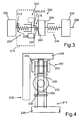
- Fig. 3 shown drive train 200 according to a particularly preferred second embodiment of the invention and provided therein, in Fig. 4 shown torsion damper 210 according to a particularly preferred second embodiment of the invention differ from the respective first embodiment only in details. Therefore, reference numerals are used for description, which are increased by 100 with respect to the respective first embodiment. The corresponding description is hereby incorporated by reference and referenced.
- an internal combustion engine 202 and an electric motor 204 is provided to serve to drive via a gearbox 206, an output shaft 208.
- the internal combustion engine 202 is preferably a 4, 5 or 6 cylinder petrol or diesel engine.
- the e-machine 204 is an aggregate which allows both motor and generator operation.
- the manual transmission 206 is a transmission with five, six or seven forward gears. A reverse gear is not mandatory, since a reverse drive on the electric motor 204 can be displayed. When driven by the engine 202, these as well as the electric motor 204 and the manual transmission 206 constitute a three-mass system.
- a torsional damper 210 is provided according to a particularly preferred first embodiment of the invention, the input side 212 with a crankshaft (not shown) of the internal combustion engine 202 is rotationally connected and its output side 214 rotationally connected to an input side 216 of a clutch 218 is.
- the clutch 218 is designed as a wet clutch.
- An output side 220 of the clutch 218 is rotationally connected to a shaft 222 of the electric motor 204.
- the torsion damper 210 which in Fig. 4 shown in a simplified section is constructed as a first spring and damping system 224 in the manner of a two-mass flywheel, wherein a first rotational mass 226 is arranged on the input side 212.
- the second embodiment also has a cage device 228 with a plurality of cages 230, these cages 230 serving to receive compression springs 232.
- the duckbill 232 is supported on the respective cage 230.
- the springs 232 are supported with their other side on a central ring 250, said central ring 250 is in operative connection with the first rotational mass 226.
- the cage device 228 is optionally supported via a hub on a shaft 238, wherein the shaft 238 may be formed as part of the coupling 218.
- the torsion damper 210 further includes a centrifugal pendulum device 240, which may also be referred to as a centrifugal pendulum.
- This centrifugal pendulum device 240 has pendulum masses 242, 244, which oscillate in curved paths in the centrifugal force field. Therefore, the frequency of the pendulum increases with speed and can cancel the rotational nonuniformity over the entire speed range.
- centrifugal pendulum device 240 is arranged radially outside of the cage device 228 with the compression springs 232 in an axially identical position. However, both the centrifugal pendulum device 240 and the cage device 228 with the compression springs 232 are located within the contour determined by the first rotational mass 226.
- a second spring and damping system 246 is arranged between the electric motor 204 and the gear 206.
Landscapes
- Engineering & Computer Science (AREA)
- Mechanical Engineering (AREA)
- Chemical & Material Sciences (AREA)
- Combustion & Propulsion (AREA)
- Transportation (AREA)
- General Engineering & Computer Science (AREA)
- Physics & Mathematics (AREA)
- Acoustics & Sound (AREA)
- Aviation & Aerospace Engineering (AREA)
- Hybrid Electric Vehicles (AREA)
- Mechanical Operated Clutches (AREA)
- Arrangement Of Transmissions (AREA)
Claims (5)
- Chaîne cinématique comportant un moteur à combustion interne (102, 202), un moteur électrique (104, 204), un embrayage (118, 218) et une boîte de vitesses (106, 206),
entre le moteur à combustion interne (102, 202) et le moteur électrique (104, 204) est disposé un premier système de ressorts et d'amortissement (124, 224), le système d'amortissement et de ressort (124, 224) présentant un dispositif de pendule à force centrifuge, le moteur électrique (104; 204) est disposé côté boîte de vitesses de l'embrayage (118; 218) et l'embrayage (218) côté boîte de vitesse du dispositif de pendule à force centrifuge (240), le côté d'entrée (216) de l'embrayage (218) étant couplé de manière solidaire en rotation à un côté de sortie du dispositif de pendule à force centrifuge (240), et entre le moteur électrique (104; 204) et la boîte de vitesses (106; 206) est disposé un second système de ressorts et d'amortissement (146, 246). - Chaîne cinématique selon la revendication 1, caractérisé en ce que le premier système de ressorts et d'amortissement (124, 224) est conçu comme un amortisseur de torsion (110, 210), en particulier comme un double volant amortisseur et le dispositif de pendule à force centrifuge (140, 240) présente des ressorts (132, 232) sur le premier rayon et sur le second rayon, le second rayon étant supérieur au premier rayon.
- Chaîne cinématique selon la revendication 1 ou la revendication 2, caractérisé en ce que les ressorts (132) sont disposés dans le flux des moments à partir du moteur à combustion interne (102) vers la boîte de vitesses (106) côté moteur à combustion interne du dispositif de pendule à force centrifuge (140).
- Chaîne cinématique selon l'une quelconque des revendications 1 à 3, caractérisé en ce que le dispositif de pendule à force centrifuge (140, 240) est disposé sur une masse rotative (126, 226).
- Procédé selon l'une quelconque des revendications 1 à 4, caractérisé en ce que l'embrayage (118, 218) est formé comme un embrayage humide.
Applications Claiming Priority (2)
| Application Number | Priority Date | Filing Date | Title |
|---|---|---|---|
| DE102009012485A DE102009012485A1 (de) | 2009-03-12 | 2009-03-12 | Antriebsstrang für Hybridantriebe sowie Torsionsdämpfer |
| PCT/EP2010/001463 WO2010102789A1 (fr) | 2009-03-12 | 2010-03-09 | Chaîne cinématique pour propulsions hybrides, et amortisseur de torsion |
Publications (3)
| Publication Number | Publication Date |
|---|---|
| EP2406521A1 EP2406521A1 (fr) | 2012-01-18 |
| EP2406521B1 true EP2406521B1 (fr) | 2015-02-25 |
| EP2406521B2 EP2406521B2 (fr) | 2019-01-09 |
Family
ID=42244435
Family Applications (1)
| Application Number | Title | Priority Date | Filing Date |
|---|---|---|---|
| EP10711330.0A Active EP2406521B2 (fr) | 2009-03-12 | 2010-03-09 | Chaîne cinématique pour propulsions hybrides, et amortisseur de torsion |
Country Status (4)
| Country | Link |
|---|---|
| US (1) | US8621957B2 (fr) |
| EP (1) | EP2406521B2 (fr) |
| DE (1) | DE102009012485A1 (fr) |
| WO (1) | WO2010102789A1 (fr) |
Families Citing this family (23)
| Publication number | Priority date | Publication date | Assignee | Title |
|---|---|---|---|---|
| WO2007112081A1 (fr) | 2006-03-24 | 2007-10-04 | Micrablate | Ligne de transmission avec capacité de transfert de chaleur |
| DE112011101230A5 (de) * | 2010-04-06 | 2013-01-24 | Schaeffler Technologies AG & Co. KG | Geteiltes Schwungrad |
| CN102893055B (zh) * | 2010-05-07 | 2014-11-26 | Zf腓特烈斯哈芬股份公司 | 扭矩传递组件及具有该扭矩传递组件的传动系统 |
| EP2694312B1 (fr) * | 2011-04-04 | 2015-03-04 | Schaeffler Technologies AG & Co. KG | Dispositif pour la transmission d'un couple |
| DE102011017660A1 (de) * | 2011-04-28 | 2012-10-31 | Zf Friedrichshafen Ag | Drehmomentübertragungsanordnung |
| EP2788604B1 (fr) * | 2011-12-05 | 2017-03-01 | Schaeffler Technologies AG & Co. KG | Chaîne cinématique |
| AT512380B1 (de) * | 2011-12-29 | 2015-06-15 | Avl List Gmbh | Zweimassensystem für eine antriebseinrichtung |
| AT512516B1 (de) * | 2012-05-10 | 2013-09-15 | Avl List Gmbh | Vibrationsdämpfung für einen Range-Extender |
| DE102013213422B4 (de) | 2012-07-10 | 2023-01-12 | Schaeffler Technologies AG & Co. KG | Drehmomentkupplung für Hybridantriebe |
| DE102012018034A1 (de) * | 2012-09-13 | 2014-02-20 | Audi Ag | Torsionsdämpfervorrichtung und Antriebsvorrichtung für ein Kraftfahrzeug |
| DE102012219728A1 (de) * | 2012-10-29 | 2014-04-30 | Zf Friedrichshafen Ag | Hybridantriebsmodul und Antriebsstrang |
| KR101417531B1 (ko) | 2012-12-28 | 2014-07-08 | 현대자동차주식회사 | 토셔널 댐퍼 |
| US9234562B2 (en) * | 2013-03-13 | 2016-01-12 | Fuji Jukogyo Kabushiki Kaisha | Damper device |
| FR3015380B1 (fr) * | 2013-12-19 | 2016-01-08 | Valeo Embrayages | Ensemble de transmission pour vehicule hybride equipe d'un amortisseur pendulaire |
| DE102016217220A1 (de) * | 2016-09-09 | 2018-03-15 | Schaeffler Technologies AG & Co. KG | Hybridmodul |
| DE102016014525A1 (de) | 2016-12-07 | 2018-06-07 | Volkswagen Ag | Hybrid-Antriebsstrang für ein Fahrzeug |
| CN107132859B (zh) * | 2017-03-24 | 2023-04-04 | 中国第一汽车股份有限公司 | 一种搭载湿式双离合器变速器的传动系扭振控制方法 |
| DE102017107888A1 (de) * | 2017-04-12 | 2018-10-18 | Schaeffler Technologies AG & Co. KG | Hybrid-Antriebsstrang mit einem ersten Torsionsschwingungsdämpfer und einem dem ersten Torsionsschwingungsdämpfer nachgeschalteten Torsionsschwingungsdämpfer |
| JP6870545B2 (ja) | 2017-09-05 | 2021-05-12 | トヨタ自動車株式会社 | ハイブリッド車両 |
| DE102018001858A1 (de) * | 2018-03-08 | 2019-09-12 | Borgwarner Inc. | Drehmomentübertragungsanordnung, Antriebsstrang mit einer solchen Drehmomentübertragungsanordnung und Fliehkraftpendeleinrichtung für eine solche Drehmomentübertragungsanordnung |
| KR20210105647A (ko) * | 2020-02-19 | 2021-08-27 | 현대트랜시스 주식회사 | 하이브리드 차량용 동력전달장치 |
| DE102024103523A1 (de) * | 2024-02-08 | 2025-08-14 | Audi Aktiengesellschaft | Elektromaschine |
| US20260045849A1 (en) * | 2024-08-12 | 2026-02-12 | Fca Us Llc | Vibration absorber for vehicle electric generator |
Family Cites Families (21)
| Publication number | Priority date | Publication date | Assignee | Title |
|---|---|---|---|---|
| US1882280A (en) * | 1925-06-27 | 1932-10-11 | Packard Motor Car Co | Damping device |
| US2480946A (en) * | 1943-09-02 | 1949-09-06 | Gen Motors Corp | Torsional vibration damper |
| DE3545857C1 (en) | 1985-02-14 | 1987-02-26 | Daimler Benz Ag | Device for reducing engine-induced vibrations in a drive line |
| DE3609149A1 (de) | 1986-03-19 | 1987-10-01 | Daimler Benz Ag | Vorrichtung zur verringerung von motorseitig erregten schwingungen eines antriebsstranges, insbesondere geteiltes schwungrad |
| DE19618864C2 (de) * | 1996-05-10 | 2003-02-27 | Zf Sachs Ag | Torsionsschwingungsdämpfer mit einer Ausgleichsschwungmasse |
| GB2346351A (en) * | 1999-02-06 | 2000-08-09 | Rover Group | A motor vehicle having an electric motor for damping torque changes |
| DE19913015B4 (de) * | 1999-03-23 | 2009-06-04 | Zf Sachs Ag | Schwingungsdämpfungssystem |
| DE10025853A1 (de) † | 1999-06-02 | 2001-04-19 | Luk Lamellen & Kupplungsbau | Antriebsstrang und Verfahren zu dessen Betrieb |
| DE10154147C1 (de) * | 2001-11-03 | 2003-07-24 | Daimler Chrysler Ag | Hybridantrieb |
| DE102004002061A1 (de) * | 2004-01-15 | 2005-08-04 | Zf Friedrichshafen Ag | Verfahren zum Steuern und Regeln eines Antriebsstranges eines Hybridfahrzeuges und Antriebsstrang eines Hybridfahrzeugs |
| EP1712394A3 (fr) * | 2005-04-12 | 2006-11-08 | Nissan Motor Co., Ltd. | Propulsion hybride avec un amortisseur de vibrations de torsion |
| JP4239102B2 (ja) * | 2005-07-05 | 2009-03-18 | アイシン・エィ・ダブリュ株式会社 | ハイブリッド車用駆動装置 |
| DE102006028556B4 (de) * | 2005-07-11 | 2019-10-10 | Schaeffler Technologies AG & Co. KG | Drehmomentübertragungseinrichtung |
| DE102006028552B4 (de) * | 2005-10-29 | 2024-05-08 | Schaeffler Technologies AG & Co. KG | Kupplungseinrichtung mit Kupplungsscheibe |
| DE102006033087B4 (de) * | 2006-07-14 | 2022-05-19 | Zf Friedrichshafen Ag | Hybridantrieb für ein Fahrzeug |
| KR100836298B1 (ko) † | 2006-10-18 | 2008-06-09 | 현대자동차주식회사 | 하이브리드 파워트레인용 클러치 |
| US8585541B2 (en) * | 2008-06-02 | 2013-11-19 | Schaeffler Technologies AG & Co. KG | Combined power transmission and drive unit for use in hybrid systems and a hybrid system |
| DE102009038198A1 (de) * | 2008-09-08 | 2010-03-11 | Luk Lamellen Und Kupplungsbau Beteiligungs Kg | Kombinierte Kraftübertragungs- und Anfahreinheit und Antriebssystem |
| US8152682B2 (en) * | 2008-09-16 | 2012-04-10 | GM Global Technology Operations LLC | 8-Speed hybrid transmission architectures |
| DE102009040367A1 (de) * | 2008-09-26 | 2010-04-08 | Luk Lamellen Und Kupplungsbau Beteiligungs Kg | Kombinierte Kraftübertragungs- und Antriebseinheit für den Einsatz in Hybridsystemen und Hybridsystem |
| US8256562B2 (en) * | 2009-09-02 | 2012-09-04 | GM Global Technology Operations LLC | Powertrain having multi-stage damper |
-
2009
- 2009-03-12 DE DE102009012485A patent/DE102009012485A1/de not_active Withdrawn
-
2010
- 2010-03-09 EP EP10711330.0A patent/EP2406521B2/fr active Active
- 2010-03-09 WO PCT/EP2010/001463 patent/WO2010102789A1/fr not_active Ceased
-
2011
- 2011-09-06 US US13/199,663 patent/US8621957B2/en active Active
Also Published As
| Publication number | Publication date |
|---|---|
| US8621957B2 (en) | 2014-01-07 |
| DE102009012485A1 (de) | 2010-09-16 |
| EP2406521A1 (fr) | 2012-01-18 |
| US20120055283A1 (en) | 2012-03-08 |
| EP2406521B2 (fr) | 2019-01-09 |
| WO2010102789A1 (fr) | 2010-09-16 |
Similar Documents
| Publication | Publication Date | Title |
|---|---|---|
| EP2406521B1 (fr) | Chaîne cinématique pour propulsions hybrides, et amortisseur de torsion | |
| DE112008003167B4 (de) | Kraftübertragungsvorrichtung mit einem drehzahladaptiven Tilger und Verfahren zur Verbesserung des Dämpfungsverhaltens | |
| DE102010025582A1 (de) | Drehmomentübertragungseinrichtung | |
| DE102011076790A1 (de) | Antriebssystem für ein Fahrzeug | |
| WO2018046048A1 (fr) | Module hybride | |
| DE102012205761A1 (de) | Drehmomentwandler | |
| DE102016219773B4 (de) | Kupplungsscheibe, Reibungskupplungseinrichtung und Antriebsstrang | |
| EP3060828A1 (fr) | Dispositif d'isolement vis-à-vis de vibrations de torsion | |
| EP2148955B1 (fr) | Engin de travaux publics automoteur | |
| WO2014079442A1 (fr) | Convertisseur de couple hydrodynamique | |
| DE102010053542A1 (de) | Drehschwingungsdämpfer | |
| DE102012209897A1 (de) | Nabeneinrichtung für einen Torsionsschwingungsdämpfer und entsprechender Torsionsschwingungsdämpfer | |
| WO2012022294A2 (fr) | Disque d'embrayage pour embrayage à friction | |
| EP2743542A2 (fr) | Systèmes d'accouplement | |
| WO2017158131A2 (fr) | Système bielle-manivelle avec amortisseur de vibrations torsionnelles | |
| DE10018955A1 (de) | Schwingungsdämpfersystem | |
| DE102019104081A1 (de) | Kupplungsaggregat | |
| DE102018115796A1 (de) | Drehmomentübertragungseinrichtung | |
| EP3052834B1 (fr) | Dispositif d'accouplement conçu pour un embrayage à friction et un amortisseur de vibrations de torsion | |
| WO2020228899A1 (fr) | Amortisseur de vibrations de torsion comprenant un amortisseur à brides multiples et un pré-amortisseur, et système et disque d'embrayage comprenant un amortisseur de vibrations de torsion | |
| WO2017101924A1 (fr) | Pendule centrifuge découplé pour dispositif de transmission de couple | |
| EP3209900B1 (fr) | Volant d'inertie | |
| DE102019130273A1 (de) | Drehmomentübertragungseinrichtung | |
| DE102010055536A1 (de) | Antriebsstrang für ein Kraftfahrzeug | |
| DE102009042634A1 (de) | Dämpfungseinrichtung |
Legal Events
| Date | Code | Title | Description |
|---|---|---|---|
| PUAI | Public reference made under article 153(3) epc to a published international application that has entered the european phase |
Free format text: ORIGINAL CODE: 0009012 |
|
| 17P | Request for examination filed |
Effective date: 20110826 |
|
| AK | Designated contracting states |
Kind code of ref document: A1 Designated state(s): AT BE BG CH CY CZ DE DK EE ES FI FR GB GR HR HU IE IS IT LI LT LU LV MC MK MT NL NO PL PT RO SE SI SK SM TR |
|
| DAX | Request for extension of the european patent (deleted) | ||
| 17Q | First examination report despatched |
Effective date: 20130906 |
|
| REG | Reference to a national code |
Ref country code: DE Ref legal event code: R079 Ref document number: 502010008954 Country of ref document: DE Free format text: PREVIOUS MAIN CLASS: F16F0015140000 Ipc: B60K0006400000 |
|
| GRAP | Despatch of communication of intention to grant a patent |
Free format text: ORIGINAL CODE: EPIDOSNIGR1 |
|
| RIC1 | Information provided on ipc code assigned before grant |
Ipc: B60K 6/40 20071001AFI20140827BHEP Ipc: B60K 6/48 20071001ALI20140827BHEP Ipc: F16F 15/14 20060101ALI20140827BHEP |
|
| INTG | Intention to grant announced |
Effective date: 20140909 |
|
| GRAS | Grant fee paid |
Free format text: ORIGINAL CODE: EPIDOSNIGR3 |
|
| GRAA | (expected) grant |
Free format text: ORIGINAL CODE: 0009210 |
|
| AK | Designated contracting states |
Kind code of ref document: B1 Designated state(s): AT BE BG CH CY CZ DE DK EE ES FI FR GB GR HR HU IE IS IT LI LT LU LV MC MK MT NL NO PL PT RO SE SI SK SM TR |
|
| REG | Reference to a national code |
Ref country code: GB Ref legal event code: FG4D Free format text: NOT ENGLISH |
|
| REG | Reference to a national code |
Ref country code: CH Ref legal event code: EP |
|
| REG | Reference to a national code |
Ref country code: IE Ref legal event code: FG4D Free format text: LANGUAGE OF EP DOCUMENT: GERMAN |
|
| REG | Reference to a national code |
Ref country code: FR Ref legal event code: PLFP Year of fee payment: 6 |
|
| REG | Reference to a national code |
Ref country code: DE Ref legal event code: R096 Ref document number: 502010008954 Country of ref document: DE Effective date: 20150409 |
|
| REG | Reference to a national code |
Ref country code: AT Ref legal event code: REF Ref document number: 711638 Country of ref document: AT Kind code of ref document: T Effective date: 20150415 |
|
| REG | Reference to a national code |
Ref country code: NL Ref legal event code: VDEP Effective date: 20150225 |
|
| REG | Reference to a national code |
Ref country code: LT Ref legal event code: MG4D |
|
| PG25 | Lapsed in a contracting state [announced via postgrant information from national office to epo] |
Ref country code: LT Free format text: LAPSE BECAUSE OF FAILURE TO SUBMIT A TRANSLATION OF THE DESCRIPTION OR TO PAY THE FEE WITHIN THE PRESCRIBED TIME-LIMIT Effective date: 20150225 Ref country code: FI Free format text: LAPSE BECAUSE OF FAILURE TO SUBMIT A TRANSLATION OF THE DESCRIPTION OR TO PAY THE FEE WITHIN THE PRESCRIBED TIME-LIMIT Effective date: 20150225 Ref country code: NO Free format text: LAPSE BECAUSE OF FAILURE TO SUBMIT A TRANSLATION OF THE DESCRIPTION OR TO PAY THE FEE WITHIN THE PRESCRIBED TIME-LIMIT Effective date: 20150525 Ref country code: ES Free format text: LAPSE BECAUSE OF FAILURE TO SUBMIT A TRANSLATION OF THE DESCRIPTION OR TO PAY THE FEE WITHIN THE PRESCRIBED TIME-LIMIT Effective date: 20150225 Ref country code: HR Free format text: LAPSE BECAUSE OF FAILURE TO SUBMIT A TRANSLATION OF THE DESCRIPTION OR TO PAY THE FEE WITHIN THE PRESCRIBED TIME-LIMIT Effective date: 20150225 Ref country code: SE Free format text: LAPSE BECAUSE OF FAILURE TO SUBMIT A TRANSLATION OF THE DESCRIPTION OR TO PAY THE FEE WITHIN THE PRESCRIBED TIME-LIMIT Effective date: 20150225 |
|
| PG25 | Lapsed in a contracting state [announced via postgrant information from national office to epo] |
Ref country code: GR Free format text: LAPSE BECAUSE OF FAILURE TO SUBMIT A TRANSLATION OF THE DESCRIPTION OR TO PAY THE FEE WITHIN THE PRESCRIBED TIME-LIMIT Effective date: 20150526 Ref country code: IS Free format text: LAPSE BECAUSE OF FAILURE TO SUBMIT A TRANSLATION OF THE DESCRIPTION OR TO PAY THE FEE WITHIN THE PRESCRIBED TIME-LIMIT Effective date: 20150625 Ref country code: LV Free format text: LAPSE BECAUSE OF FAILURE TO SUBMIT A TRANSLATION OF THE DESCRIPTION OR TO PAY THE FEE WITHIN THE PRESCRIBED TIME-LIMIT Effective date: 20150225 |
|
| PG25 | Lapsed in a contracting state [announced via postgrant information from national office to epo] |
Ref country code: NL Free format text: LAPSE BECAUSE OF FAILURE TO SUBMIT A TRANSLATION OF THE DESCRIPTION OR TO PAY THE FEE WITHIN THE PRESCRIBED TIME-LIMIT Effective date: 20150225 |
|
| PG25 | Lapsed in a contracting state [announced via postgrant information from national office to epo] |
Ref country code: CZ Free format text: LAPSE BECAUSE OF FAILURE TO SUBMIT A TRANSLATION OF THE DESCRIPTION OR TO PAY THE FEE WITHIN THE PRESCRIBED TIME-LIMIT Effective date: 20150225 Ref country code: RO Free format text: LAPSE BECAUSE OF FAILURE TO SUBMIT A TRANSLATION OF THE DESCRIPTION OR TO PAY THE FEE WITHIN THE PRESCRIBED TIME-LIMIT Effective date: 20150225 Ref country code: EE Free format text: LAPSE BECAUSE OF FAILURE TO SUBMIT A TRANSLATION OF THE DESCRIPTION OR TO PAY THE FEE WITHIN THE PRESCRIBED TIME-LIMIT Effective date: 20150225 Ref country code: DK Free format text: LAPSE BECAUSE OF FAILURE TO SUBMIT A TRANSLATION OF THE DESCRIPTION OR TO PAY THE FEE WITHIN THE PRESCRIBED TIME-LIMIT Effective date: 20150225 Ref country code: SK Free format text: LAPSE BECAUSE OF FAILURE TO SUBMIT A TRANSLATION OF THE DESCRIPTION OR TO PAY THE FEE WITHIN THE PRESCRIBED TIME-LIMIT Effective date: 20150225 |
|
| REG | Reference to a national code |
Ref country code: CH Ref legal event code: PL |
|
| REG | Reference to a national code |
Ref country code: DE Ref legal event code: R026 Ref document number: 502010008954 Country of ref document: DE |
|
| PLBI | Opposition filed |
Free format text: ORIGINAL CODE: 0009260 |
|
| PG25 | Lapsed in a contracting state [announced via postgrant information from national office to epo] |
Ref country code: PL Free format text: LAPSE BECAUSE OF FAILURE TO SUBMIT A TRANSLATION OF THE DESCRIPTION OR TO PAY THE FEE WITHIN THE PRESCRIBED TIME-LIMIT Effective date: 20150225 Ref country code: MC Free format text: LAPSE BECAUSE OF FAILURE TO SUBMIT A TRANSLATION OF THE DESCRIPTION OR TO PAY THE FEE WITHIN THE PRESCRIBED TIME-LIMIT Effective date: 20150225 |
|
| 26 | Opposition filed |
Opponent name: ZF FRIEDRICHSHAFEN AG Effective date: 20151125 |
|
| PG25 | Lapsed in a contracting state [announced via postgrant information from national office to epo] |
Ref country code: IT Free format text: LAPSE BECAUSE OF FAILURE TO SUBMIT A TRANSLATION OF THE DESCRIPTION OR TO PAY THE FEE WITHIN THE PRESCRIBED TIME-LIMIT Effective date: 20150225 |
|
| PLAF | Information modified related to communication of a notice of opposition and request to file observations + time limit |
Free format text: ORIGINAL CODE: EPIDOSCOBS2 |
|
| PLAX | Notice of opposition and request to file observation + time limit sent |
Free format text: ORIGINAL CODE: EPIDOSNOBS2 |
|
| REG | Reference to a national code |
Ref country code: IE Ref legal event code: MM4A |
|
| PG25 | Lapsed in a contracting state [announced via postgrant information from national office to epo] |
Ref country code: CH Free format text: LAPSE BECAUSE OF NON-PAYMENT OF DUE FEES Effective date: 20150331 Ref country code: LI Free format text: LAPSE BECAUSE OF NON-PAYMENT OF DUE FEES Effective date: 20150331 Ref country code: IE Free format text: LAPSE BECAUSE OF NON-PAYMENT OF DUE FEES Effective date: 20150309 |
|
| PG25 | Lapsed in a contracting state [announced via postgrant information from national office to epo] |
Ref country code: SI Free format text: LAPSE BECAUSE OF FAILURE TO SUBMIT A TRANSLATION OF THE DESCRIPTION OR TO PAY THE FEE WITHIN THE PRESCRIBED TIME-LIMIT Effective date: 20150225 |
|
| REG | Reference to a national code |
Ref country code: FR Ref legal event code: PLFP Year of fee payment: 7 |
|
| REG | Reference to a national code |
Ref country code: AT Ref legal event code: MM01 Ref document number: 711638 Country of ref document: AT Kind code of ref document: T Effective date: 20150309 |
|
| PLAF | Information modified related to communication of a notice of opposition and request to file observations + time limit |
Free format text: ORIGINAL CODE: EPIDOSCOBS2 |
|
| PLBB | Reply of patent proprietor to notice(s) of opposition received |
Free format text: ORIGINAL CODE: EPIDOSNOBS3 |
|
| PG25 | Lapsed in a contracting state [announced via postgrant information from national office to epo] |
Ref country code: AT Free format text: LAPSE BECAUSE OF NON-PAYMENT OF DUE FEES Effective date: 20150309 |
|
| PG25 | Lapsed in a contracting state [announced via postgrant information from national office to epo] |
Ref country code: MT Free format text: LAPSE BECAUSE OF FAILURE TO SUBMIT A TRANSLATION OF THE DESCRIPTION OR TO PAY THE FEE WITHIN THE PRESCRIBED TIME-LIMIT Effective date: 20150225 |
|
| REG | Reference to a national code |
Ref country code: FR Ref legal event code: PLFP Year of fee payment: 8 |
|
| PG25 | Lapsed in a contracting state [announced via postgrant information from national office to epo] |
Ref country code: SM Free format text: LAPSE BECAUSE OF FAILURE TO SUBMIT A TRANSLATION OF THE DESCRIPTION OR TO PAY THE FEE WITHIN THE PRESCRIBED TIME-LIMIT Effective date: 20150225 Ref country code: BG Free format text: LAPSE BECAUSE OF FAILURE TO SUBMIT A TRANSLATION OF THE DESCRIPTION OR TO PAY THE FEE WITHIN THE PRESCRIBED TIME-LIMIT Effective date: 20150225 Ref country code: HU Free format text: LAPSE BECAUSE OF FAILURE TO SUBMIT A TRANSLATION OF THE DESCRIPTION OR TO PAY THE FEE WITHIN THE PRESCRIBED TIME-LIMIT; INVALID AB INITIO Effective date: 20100309 |
|
| PG25 | Lapsed in a contracting state [announced via postgrant information from national office to epo] |
Ref country code: CY Free format text: LAPSE BECAUSE OF FAILURE TO SUBMIT A TRANSLATION OF THE DESCRIPTION OR TO PAY THE FEE WITHIN THE PRESCRIBED TIME-LIMIT Effective date: 20150225 |
|
| PG25 | Lapsed in a contracting state [announced via postgrant information from national office to epo] |
Ref country code: PT Free format text: LAPSE BECAUSE OF FAILURE TO SUBMIT A TRANSLATION OF THE DESCRIPTION OR TO PAY THE FEE WITHIN THE PRESCRIBED TIME-LIMIT Effective date: 20150625 Ref country code: BE Free format text: LAPSE BECAUSE OF NON-PAYMENT OF DUE FEES Effective date: 20150331 |
|
| PG25 | Lapsed in a contracting state [announced via postgrant information from national office to epo] |
Ref country code: TR Free format text: LAPSE BECAUSE OF FAILURE TO SUBMIT A TRANSLATION OF THE DESCRIPTION OR TO PAY THE FEE WITHIN THE PRESCRIBED TIME-LIMIT Effective date: 20150225 |
|
| PG25 | Lapsed in a contracting state [announced via postgrant information from national office to epo] |
Ref country code: LU Free format text: LAPSE BECAUSE OF NON-PAYMENT OF DUE FEES Effective date: 20150309 |
|
| REG | Reference to a national code |
Ref country code: FR Ref legal event code: PLFP Year of fee payment: 9 |
|
| PG25 | Lapsed in a contracting state [announced via postgrant information from national office to epo] |
Ref country code: MK Free format text: LAPSE BECAUSE OF FAILURE TO SUBMIT A TRANSLATION OF THE DESCRIPTION OR TO PAY THE FEE WITHIN THE PRESCRIBED TIME-LIMIT Effective date: 20150225 |
|
| PUAH | Patent maintained in amended form |
Free format text: ORIGINAL CODE: 0009272 |
|
| STAA | Information on the status of an ep patent application or granted ep patent |
Free format text: STATUS: PATENT MAINTAINED AS AMENDED |
|
| 27A | Patent maintained in amended form |
Effective date: 20190109 |
|
| AK | Designated contracting states |
Kind code of ref document: B2 Designated state(s): AT BE BG CH CY CZ DE DK EE ES FI FR GB GR HR HU IE IS IT LI LT LU LV MC MK MT NL NO PL PT RO SE SI SK SM TR |
|
| REG | Reference to a national code |
Ref country code: DE Ref legal event code: R102 Ref document number: 502010008954 Country of ref document: DE |
|
| RIC2 | Information provided on ipc code assigned after grant |
Ipc: F16F 15/14 20060101ALI20140827BHEP Ipc: B60K 6/40 20071001AFI20140827BHEP Ipc: B60K 6/48 20071001ALI20140827BHEP |
|
| PGFP | Annual fee paid to national office [announced via postgrant information from national office to epo] |
Ref country code: GB Payment date: 20200326 Year of fee payment: 11 |
|
| PGFP | Annual fee paid to national office [announced via postgrant information from national office to epo] |
Ref country code: FR Payment date: 20200326 Year of fee payment: 11 |
|
| REG | Reference to a national code |
Ref country code: DE Ref legal event code: R081 Ref document number: 502010008954 Country of ref document: DE Owner name: MERCEDES-BENZ GROUP AG, DE Free format text: FORMER OWNER: DAIMLER AG, 70327 STUTTGART, DE Ref country code: DE Ref legal event code: R082 Ref document number: 502010008954 Country of ref document: DE Representative=s name: JENSEN & SON, GB Ref country code: DE Ref legal event code: R081 Ref document number: 502010008954 Country of ref document: DE Owner name: DAIMLER AG, DE Free format text: FORMER OWNER: DAIMLER AG, 70327 STUTTGART, DE Ref country code: DE Ref legal event code: R082 Ref document number: 502010008954 Country of ref document: DE Representative=s name: JENSENS IP LIMITED, IE |
|
| REG | Reference to a national code |
Ref country code: DE Ref legal event code: R082 Ref document number: 502010008954 Country of ref document: DE Representative=s name: JENSENS IP LIMITED, IE |
|
| GBPC | Gb: european patent ceased through non-payment of renewal fee |
Effective date: 20210309 |
|
| PG25 | Lapsed in a contracting state [announced via postgrant information from national office to epo] |
Ref country code: FR Free format text: LAPSE BECAUSE OF NON-PAYMENT OF DUE FEES Effective date: 20210331 Ref country code: GB Free format text: LAPSE BECAUSE OF NON-PAYMENT OF DUE FEES Effective date: 20210309 |
|
| REG | Reference to a national code |
Ref country code: DE Ref legal event code: R081 Ref document number: 502010008954 Country of ref document: DE Owner name: MERCEDES-BENZ GROUP AG, DE Free format text: FORMER OWNER: DAIMLER AG, STUTTGART, DE Ref country code: DE Ref legal event code: R082 Ref document number: 502010008954 Country of ref document: DE |
|
| PGFP | Annual fee paid to national office [announced via postgrant information from national office to epo] |
Ref country code: DE Payment date: 20260320 Year of fee payment: 17 |