EP2407992B1 - Antriebs- und Steuerungseinheit für eine Nieder- oder Mittelspannungsvorrichtung - Google Patents
Antriebs- und Steuerungseinheit für eine Nieder- oder Mittelspannungsvorrichtung Download PDFInfo
- Publication number
- EP2407992B1 EP2407992B1 EP20100169635 EP10169635A EP2407992B1 EP 2407992 B1 EP2407992 B1 EP 2407992B1 EP 20100169635 EP20100169635 EP 20100169635 EP 10169635 A EP10169635 A EP 10169635A EP 2407992 B1 EP2407992 B1 EP 2407992B1
- Authority
- EP
- European Patent Office
- Prior art keywords
- power
- control unit
- low
- function
- voltage
- Prior art date
- Legal status (The legal status is an assumption and is not a legal conclusion. Google has not performed a legal analysis and makes no representation as to the accuracy of the status listed.)
- Active
Links
Images

Classifications
-
- H—ELECTRICITY
- H01—ELECTRIC ELEMENTS
- H01H—ELECTRIC SWITCHES; RELAYS; SELECTORS; EMERGENCY PROTECTIVE DEVICES
- H01H47/00—Circuit arrangements not adapted to a particular application of the relay and designed to obtain desired operating characteristics or to provide energising current
- H01H47/002—Monitoring or fail-safe circuits
-
- H—ELECTRICITY
- H02—GENERATION; CONVERSION OR DISTRIBUTION OF ELECTRIC POWER
- H02H—EMERGENCY PROTECTIVE CIRCUIT ARRANGEMENTS
- H02H3/00—Emergency protective circuit arrangements for automatic disconnection directly responsive to an undesired change from normal electric working condition with or without subsequent reconnection ; integrated protection
- H02H3/02—Details
- H02H3/04—Details with warning or supervision in addition to disconnection, e.g. for indicating that protective apparatus has functioned
- H02H3/044—Checking correct functioning of protective arrangements, e.g. by simulating a fault
Definitions
- the present invention relates to a power and control unit for a low and medium voltage apparatus having improved features in terms of performances and functionality.
- the power and control unit of the invention is conveniently used in trip circuits of low or medium voltage apparatuses.
- medium voltage is referred to applications in the range of between 1 and 50 kV and low voltage is referred to applications in the range below 1kV.
- Electronic devices for power and control purposes are conveniently used in low and medium voltage apparatuses (e.g., circuit breakers, contactors, disconnectors) to actuate said apparatuses.
- the power and control electronic devices generally include some binary inputs to acquire status information and receive remote opening and closing commands for the low or medium voltage apparatus.
- typically binary inputs are used for trip commands and interlocking signals.
- Electronic devices also include electronic drivers for actuators, binary outputs, automation functions and protection functionalities. In recent times, diagnostic functions have been introduced into the electronic device to check the functionalities. In particular, electronic devices are able to check the actuators (coil/motor supervision), the internal power circuit (over-current and over-temperature protections), the capacitor banks used to store the energy for operation in magnetic actuated circuit breaker (capacitor supervision).
- binary inputs are usually part of a trip circuit which comprises a protection relay which generates a trip command.
- the electronic devices then operates the apparatus according to said trip command.
- the binary inputs of the electronic devices for power and control purposes typically have also to interface the trip circuit supervision function which is available in the binary outputs of the protection relay.
- the trip circuit supervision function is designed to check the continuity of apparatus controlled by the power and control electronic device (e.g. a coil) when the apparatus is not energized. Generally, it is able to detect an open circuit and generate an alarm indicating that the command chain is not working. Therefore the binary inputs should allow a minimum current to circulate during normal operation and the current circulation should be blocked to activate the trip circuit supervision alarm.
- a possible implementation already known in the art consists in a power resistor connected in parallel to the binary input. However such a solution has a number of disadvantages and drawbacks.
- the power resistor is always connected in parallel to the binary input.
- the power resistor When the binary input is driven with the high level control voltage, the power resistor generates high power that must be dissipated inside the power and control electronic device.
- a further disadvantage derives from the fact that in order to reduce power consumption and thermal heating the value of the resistor is kept as high as possible. This generates some problems of interoperability with the trip circuit supervision function of some relay.
- Still another disadvantage derives from the fact that this solution only allows to check the cable connection between the trip circuit supervision relay and the power and control electronic device and does not allow to detect failures in the power and control electronic device or in the low or medium voltage apparatus:
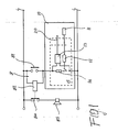
- an electronic device 10 is connected to a trip circuit 8, including a trip circuit supervision relay 82 and a contact 81.
- the trip circuit supervision relay 82 can be operatively connected to an alarm 85 through a switch 84.
- the electronic device 10 includes a binary input 15, as well as diagnostic function(s) 11, and is connected to one or more functions 20 of a low or medium voltage apparatus.
- Contact 81 controls the binary input 15, the diagnostic circuit being designed to work when contact 81 is open.
- the low impedance feedback functionally 12 allows the electronic device diagnostic 11 to reveal a failure using the binary input 15, a high impedance circuit indicating that a failure has occurred.
- neither the trip circuit supervision relay 82 nor the electronic device diagnostic 11 can check the input signal sensing block 13 of the binary input 15.
- EP 2 149 895 A1 discloses such a power and control unit.
- the present invention is aimed at providing a power and control unit for low and medium voltage applications that is able to detect failures in the connections or in the power and control unit, as well as to detect the functionality of the binary inputs used in the power and control unit itself.
- Still another object of the present invention is to provide a power and control unit for low and medium voltage applications that can be easily and effectively interfaced with existing low and medium voltage apparatuses.
- Still another object of the present invention is to provide a power and control unit for low and medium voltage applications that can be easily manufactured and at competitive costs.
- the present invention relates to a power and control unit for low and medium voltage applications operatively couplable to one or more functions of a low or medium voltage apparatus.
- the power and control unit for low and medium voltage applications comprises:
- the present invention relates to trip circuit for a low or medium voltage apparatus that comprises a power and control unit having the above described features the binary input of said power and control unit 1 being operatively connectable to said trip circuit through a switch.
- said control function comprises a low-impedance feedback and pulse generator which drives said low-impedance variable load.
- said low-impedance feedback and pulse generator advantageously drives said low-impedance variable load so that it oscillates between a first and a second value, thereby generating an oscillating input voltage detectable by said signal-detecting function.
- said control function comprises a voltage-encoding block converting said input voltage to a digital voltage signal.
- Said voltage-encoding block encodes and transmits said digitalized input voltage signal to said signal-detecting function.
- the power and control unit of the invention preferably comprises a voltage-decoding block connected in input to said voltage-encoding block and in output to said signal-detecting function.
- said signal-detecting function comprises a thresholds detection function of said binary input operatively connected to said binary input and to said one or more functions of said low or medium voltage apparatus, said thresholds detection function being preferably connected in input to said voltage-decoding block and in output to said one or more functions of said low or medium voltage apparatus.
- said signal-detecting function can comprises a pulse detection function operatively connected to said binary input and to said internal self-diagnostic function of said power and control unit, said pulse detection function being preferably connected in input to said voltage-decoding block and in output to said internal self-diagnostic function of said power and control unit.
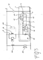
- a power and control unit for low and medium voltage applications is operatively couplable to one or more functions 20 of a low or medium voltage apparatus.
- These functions include, in general, input controlled by the power and control unit, such as, for example, actuation of a motor, one or more coils, a magnetic actuator, etc..
- power and control unit for low and medium voltage applications comprises an internal self-diagnostic function 2 which is operatively coupled to a signal-generating function 3.
- said signal-generating function 3 can comprise a Ready/Watchdog binary output, normally connected to means 31 for displaying the status of the power and control unit itself.
- the power and control unit 1 further comprises a binary input 4 which is operatively coupled to said internal self-diagnostic function 2.
- a binary input 4 which is operatively coupled to said internal self-diagnostic function 2.
- One of the characterizing features of the power and control unit 1 of the invention is given by the fact that it also comprises a low-impedance variable load which is connectable in parallel to said binary input 4.
- said binary input 4 comprises a control function 5 which is operatively connected to said low-impedance variable load 41 and also operatively connected, through a signal-detecting function 6, to said internal self-diagnostic function 2 and to said one or more functions 20 of said low or medium voltage apparatus.
- the presence of the low-impedance variable load 41 allows to develop a variable voltage that can be easily detected for diagnostic functions of the binary input itself.
- said control function 5 comprises a low-impedance feedback and pulse generator 51 which drives said low-impedance variable load 41.
- said low-impedance feedback and pulse generator 51 drives said low-impedance variable load 41 so that is oscillates between a first and a second value, thereby generating an oscillating input voltage detectable by said signal-detecting function 6.
- said control function 5 can advantageously comprises a voltage-encoding block 52 converting said input voltage to a digital voltage signal.
- Said voltage-encoding block 52 usually also encodes and transmits said digitalized input voltage signal to said signal-detecting function 6.
- the power and control unit 1 of the invention may also comprise an isolation barrier 9 separating the control function 5 from the signal-detecting function 6.
- said voltage-encoding block 52 converts said input voltage to a digital voltage signal, and encodes and transmits said digitalized input voltage signal to said signal-detecting function 6 through said isolation barrier 9.
- the power and control unit 1 of the invention preferably comprises a voltage-decoding block 7 connected in input to said voltage-encoding block 52 and in output to said signal-detecting function 6.
- said signal-detecting function 6 comprises a thresholds detection function 61 of said binary input 4 operatively connected to said binary input 4 and to said one or more functions 20 of said low or medium voltage apparatus. Said thresholds detection function 61 of said binary input 4 allows recognizing the command received by the binary inputs 4.
- said thresholds detection function 61 is connected in input to said voltage-decoding block 7 and in output to said one or more functions 20 of said low or medium voltage apparatus.
- said signal-detecting function 6 can comprise a pulse detection function 62 operatively connected to said binary input 4 and to said internal self-diagnostic function 2 of said power and control unit 1.
- said pulse detection function 62 is connected in input to said voltage-decoding block 7 and in output to said internal self diagnostic function 2 of said power and control unit 1.
- pulse detection function 62 senses the pulses generated for the diagnostic and transmit a corresponding signal to the internal self-diagnostic function 2.
- the diagnostic function 2 closes the loop: it processes all diagnostic signals coming from the binary inputs and the other circuits (e.g. coil supervision, motor supervision, over-current protection, over-temperature protection, capacitor supervision) and reveals the fault(s) using the Ready/Watchdog signal and the low impedance feedback of the same binary inputs.
- the other circuits e.g. coil supervision, motor supervision, over-current protection, over-temperature protection, capacitor supervision
- the HW/SW implementing the thresholds detection function 61 and the pulse detection function 62 can be designed in a way that they both work or they do not.
- the low-impedance feedback and pulse generator 51 together with said low-impedance variable load 41 realize a self-oscillating system controlled by the input voltage.
- the load impedance is set to a high value; as a result, the voltage start increasing.
- the load impedance is set to a low value; as a result, the voltage start decreasing.
- the voltage level used for diagnostic should be lower than the binary input threshold levels, in order to avoid interferences with the main functionalities of the binary input.
- the power and control unit of the invention finds convenient application in trip circuits of low and medium voltage apparatuses (e.g., circuit breakers, contactors, disconnectors, and similar), which are also part of the present invention.
- low and medium voltage apparatuses e.g., circuit breakers, contactors, disconnectors, and similar
- a typical example of a trip circuit for a low or medium voltage apparatus comprises a power and control unit 1 according to what described in the above, the binary input 4 of said power and control unit 1 being operatively connectable to said trip circuit through a switch 81.
- a trip circuit includes a trip circuit supervision relay 82 or a resistor 83.
- a trip circuit supervision relay 82 is used, said trip circuit supervision relay 82 being operatively connected to an alarm 85 through a switch 84.
Landscapes
- Control Of Voltage And Current In General (AREA)
- Testing Electric Properties And Detecting Electric Faults (AREA)
Claims (15)
- Leistungs- und Steuereinheit (1) für Niedrig- und Mittelspannungsanwendungen, die operativ an eine oder mehrere Funktionen (20) einer Niedrig- oder Mittelspannungsvorrichtung gekoppelt werden kann, aufweisend eine interne Selbstdiagnosefunktion (2), die operativ an eine signalgebende Funktion (3) gekoppelt ist, und einen Binäreingang (4), der operativ an die interne Selbstdiagnosefunktion (2) gekoppelt ist, dadurch gekennzeichnet, dass die Leistungs- und Steuereinheit (1) ferner eine variable Niedrigimpedanzlast (41) aufweist, die parallel mit dem Binäreingang (4) verbunden werden kann, wobei der Binäreingang (4) eine Steuerfunktion (5) aufweist, die operativ mit der variablen Niedrigimpedanzlast (41) verbunden ist und auch durch eine Signalerfassungsfunktion (6) mit der internen Selbstdiagnosefunktion (2) und mit einer oder mehreren Funktionen (20) der Niedrig- und Mittelspannungsvorrichtung verbunden ist.
- Leistungs- und Steuereinheit (1) nach Anspruch 1, dadurch gekennzeichnet, dass die Steuerfunktion (5) einen Niedrigimpedanz-Feedback- und Impulsgeber (51) aufweist, der die variable Niedrigimpedanzlast (41) ansteuert.
- Leistungs- und Steuereinheit (1) nach Anspruch 2, dadurch gekennzeichnet, dass der Niedrigimpedanz-Feedback- und Impulsgeber (51) die variable Niedrigimpedanzlast (41) ansteuert, so dass sie zwischen einem ersten und einem zweiten Wert oszilliert, wodurch eine oszillierende Eingangsspannung erzeugt wird, die von der Signalerfassungsfunktion (6) erfasst werden kann.
- Leistungs- und Steuereinheit (1) nach Anspruch 3, dadurch gekennzeichnet, dass die Steuerfunktion (5) einen Spannungsverschlüsselungsblock (52) aufweist, der die Eingangsspannung in ein digitale Spannungssignal konvertiert.
- Leistungs- und Steuereinheit (1) nach Anspruch 4, dadurch gekennzeichnet, dass der Spannungsverschlüsselungsblock (52) das digitalisierte Eingangssignal verschlüsselt und an die Signalerfassungsfunktion (6) überträgt.
- Leistungs- und Steuereinheit (1) nach Anspruch 5, dadurch gekennzeichnet, dass die Leistungs- und Steuereinheit (1) einen Spannungsentschlüsselungsblock (7) aufweist, der eingangs mit dem Spannungsverschlüsselungsblock (52) und ausgangs mit der Signalerfassungsfunktion (6) verbunden ist.
- Leistungs- und Steuereinheit (1) nach einem oder mehreren der vorgenannten Ansprüche, dadurch gekennzeichnet, dass die Signalerfassungsfunktion (6) eine Grenzwerterfassungsfunktion (61) des binären Eingangs (4) aufweist, die operativ mit dem Binäreingang (4) und einer oder mehreren Funktionen (20) der Niedrig- oder Mittelspannungsvorrichtung verbunden ist.
- Leistungs- und Steuereinheit (1) nach den Ansprüchen 6 und 7, dadurch gekennzeichnet, dass die Grenzwerterfassungsfunktion (61) eingangs mit dem Spannungsentschlüsselungsblock (7) und ausgangs mit einer oder mehreren Funktionen (20) der Niedrig- oder Mittelspannungsvorrichtung verbunden ist.
- Leistungs- und Steuereinheit (1) nach einem oder mehreren der vorgenannten Ansprüche, dadurch gekennzeichnet, dass die Signalerfassungsfunktion (6) eine Impulserfassungsfunktion (62) aufweist, die operativ mit dem Binäreingang (4) und der internen Selbstdiagnosefunktion (2) der Leistungs- und Steuereinheit (1) verbunden ist.
- Leistungs- und Steuereinheit (1) nach den Ansprüchen 6 und 9, dadurch gekennzeichnet, dass die Impulserfassungsfunktion (62) eingangs mit dem Spannungsentschlüsselungsblock (7) und ausgangs mit der internen Selbstdiagnosefunktion (2) der Leistungs- und Steuereinheit (1) verbunden ist.
- Leistungs- und Steuereinheit (1) nach einem oder mehreren der vorgenannten Ansprüche, dadurch gekennzeichnet, dass die signalgebende Funktion (3) einen Ready/Watchdog-Binärausgang aufweist.
- Auslösestromkreis für eine Niedrig- oder Mittelspannungsvorrichtung, aufweisend eine Leistungs- und Steuereinheit (1) nach einem oder mehreren der vorgenannten Ansprüche, wobei der Binäreingang (4) der Leistungs- und Steuereinheit (1) durch einen Schalter (81) operativ mit dem Auslösestromkreis verbunden werden kann.
- Auslösestromkreis nach Anspruch 12, dadurch gekennzeichnet, dass er ein Auslösestromkreis-Überwachungsrelais (82) oder einen Widerstand (83) aufweist.
- Auslösestromkreis nach Anspruch 13, dadurch gekennzeichnet, dass das Auslösestromkreis-Überwachungsrelais (82) durch einen Schalter (84) operativ mit einem Alarm (85) verbunden ist.
- Niedrig- oder Mittelspannungsvorrichtung, aufweisend einen Auslösestromkreis nach einem der Ansprüche 12 bis 14.
Priority Applications (3)
| Application Number | Priority Date | Filing Date | Title |
|---|---|---|---|
| EP20100169635 EP2407992B1 (de) | 2010-07-15 | 2010-07-15 | Antriebs- und Steuerungseinheit für eine Nieder- oder Mittelspannungsvorrichtung |
| US13/182,698 US8937795B2 (en) | 2010-07-15 | 2011-07-14 | Power and control unit for a low or medium voltage apparatus |
| CN201110197919.0A CN102340126B (zh) | 2010-07-15 | 2011-07-15 | 用于低压或中压设备的功率和控制单元 |
Applications Claiming Priority (1)
| Application Number | Priority Date | Filing Date | Title |
|---|---|---|---|
| EP20100169635 EP2407992B1 (de) | 2010-07-15 | 2010-07-15 | Antriebs- und Steuerungseinheit für eine Nieder- oder Mittelspannungsvorrichtung |
Publications (2)
| Publication Number | Publication Date |
|---|---|
| EP2407992A1 EP2407992A1 (de) | 2012-01-18 |
| EP2407992B1 true EP2407992B1 (de) | 2013-09-04 |
Family
ID=43027587
Family Applications (1)
| Application Number | Title | Priority Date | Filing Date |
|---|---|---|---|
| EP20100169635 Active EP2407992B1 (de) | 2010-07-15 | 2010-07-15 | Antriebs- und Steuerungseinheit für eine Nieder- oder Mittelspannungsvorrichtung |
Country Status (3)
| Country | Link |
|---|---|
| US (1) | US8937795B2 (de) |
| EP (1) | EP2407992B1 (de) |
| CN (1) | CN102340126B (de) |
Families Citing this family (4)
| Publication number | Priority date | Publication date | Assignee | Title |
|---|---|---|---|---|
| CN102998569A (zh) * | 2012-12-06 | 2013-03-27 | 辽宁省电力有限公司抚顺供电公司 | 便携式功放故障检测装置 |
| CN107037678B (zh) * | 2016-01-19 | 2019-07-12 | 精工爱普生株式会社 | 位置检测装置、光学装置、光源装置以及投影仪 |
| CN111614376A (zh) * | 2020-03-05 | 2020-09-01 | 国网青海省电力公司果洛供电公司 | 一种基于中压载波通讯装置的中压电力线阻抗测试系统 |
| CN114962146A (zh) * | 2022-04-13 | 2022-08-30 | 南京轻机包装机械有限公司 | 一种风力发电机组的偏航电机的保护方法 |
Family Cites Families (10)
| Publication number | Priority date | Publication date | Assignee | Title |
|---|---|---|---|---|
| JPH01185123A (ja) * | 1988-01-13 | 1989-07-24 | Fuji Electric Co Ltd | ディジタルリレーシステムの監視方式 |
| EP0775332B1 (de) * | 1995-03-11 | 2000-05-10 | Leuze electronic GmbH + Co. | Sicherheitsschalteranordnung |
| WO1999008356A1 (de) * | 1997-08-12 | 1999-02-18 | Siemens Aktiengesellschaft | Verfahren zur überwachung eines schutzgerätes |
| JPH1185123A (ja) | 1997-09-09 | 1999-03-30 | Sanyo Electric Co Ltd | カーソル表示制御回路 |
| EP1150412A1 (de) * | 2000-04-25 | 2001-10-31 | Siemens Aktiengesellschaft | Fehlerstrom-Schutzschalter und Verfahren zum Überprüfen der Funktionsfähigkeit eines Fehlerstrom-Schutzschalters |
| GB0226111D0 (en) * | 2002-11-08 | 2002-12-18 | Delta Electrical Ltd | Residual current devices |
| CN100405684C (zh) * | 2003-08-04 | 2008-07-23 | 新巨企业股份有限公司 | 弧光放电保护装置 |
| JP2008172962A (ja) * | 2007-01-12 | 2008-07-24 | Ricoh Co Ltd | 電源制御回路、機能拡張ユニット、画像形成装置、及び電源制御方法 |
| ATE523890T1 (de) * | 2008-07-31 | 2011-09-15 | Abb Technology Ag | Antriebs- und steuerungseinheit für eine nieder- oder mittelspannungsvorrichtung |
| CN101741061A (zh) * | 2008-11-24 | 2010-06-16 | 射阳伟龙电气有限公司 | 一种配电变压器中低压一体化保护方法 |
-
2010
- 2010-07-15 EP EP20100169635 patent/EP2407992B1/de active Active
-
2011
- 2011-07-14 US US13/182,698 patent/US8937795B2/en active Active
- 2011-07-15 CN CN201110197919.0A patent/CN102340126B/zh active Active
Also Published As
| Publication number | Publication date |
|---|---|
| EP2407992A1 (de) | 2012-01-18 |
| US20120014018A1 (en) | 2012-01-19 |
| US8937795B2 (en) | 2015-01-20 |
| CN102340126A (zh) | 2012-02-01 |
| CN102340126B (zh) | 2015-12-02 |
Similar Documents
| Publication | Publication Date | Title |
|---|---|---|
| EP2362408B1 (de) | Sicherheitsschaltvorrichtung mit Universalsignaleingang | |
| US9306487B2 (en) | Motor drive device having function of detecting contact fusion in electromagnetic contactor | |
| JP5281567B2 (ja) | 電動機用の制御システム | |
| KR101800084B1 (ko) | 계전 유닛, 계전 유닛의 제어 방법 | |
| JP5888972B2 (ja) | 太陽光発電システム | |
| US8154835B2 (en) | Power and control unit for a low or medium voltage apparatus | |
| EP2956394B1 (de) | Sicherheitsschaltung für einen aufzug | |
| US8937795B2 (en) | Power and control unit for a low or medium voltage apparatus | |
| US20120014032A1 (en) | Trip circuit supervision relay for low and medium voltage applications | |
| EP2503849B1 (de) | Diskrete Eingangssignalerzeugung über Ausgangskurzschlussschaltungserkennung | |
| KR101785160B1 (ko) | 계전 유닛 및 계전 회로의 제어 방법 | |
| EP2988142A2 (de) | Überwachungseinheit zur überwachung eines schaltzustandes und/oder eines elektrischen zustandes eines hochspannungsschaltersystems, überwachungssystem und verfahren | |
| US20170125182A1 (en) | Switchgear | |
| CN107783525A (zh) | 基于fpga的di动态诊断电路 | |
| US10063045B2 (en) | Coil actuator a for low and medium voltage switching apparatus and an arc fault coil suppression device comprising said coil actuator | |
| JP6698414B2 (ja) | 送電回線保護システム | |
| US6208536B1 (en) | Safety device for a drive mechanism | |
| KR100804518B1 (ko) | 누설 전류를 2단계로 감지하여 오동작을 방지하는 누전차단 방법 및 그 장치 | |
| US10749330B2 (en) | Device and method for monitoring the activity of processing units in an electric trip switch | |
| KR102682041B1 (ko) | 차량 및 차량용 인터락 모니터링 회로 | |
| KR101662909B1 (ko) | 모터의 정지를 방지하는 장치 | |
| KR102337590B1 (ko) | 보호계전기 | |
| CN121721377A (zh) | 功率变换器及其故障指示方法 | |
| WO2018216167A1 (ja) | 電子式回路遮断器 |
Legal Events
| Date | Code | Title | Description |
|---|---|---|---|
| AK | Designated contracting states |
Kind code of ref document: A1 Designated state(s): AL AT BE BG CH CY CZ DE DK EE ES FI FR GB GR HR HU IE IS IT LI LT LU LV MC MK MT NL NO PL PT RO SE SI SK SM TR |
|
| AX | Request for extension of the european patent |
Extension state: BA ME RS |
|
| PUAI | Public reference made under article 153(3) epc to a published international application that has entered the european phase |
Free format text: ORIGINAL CODE: 0009012 |
|
| 17P | Request for examination filed |
Effective date: 20120625 |
|
| GRAP | Despatch of communication of intention to grant a patent |
Free format text: ORIGINAL CODE: EPIDOSNIGR1 |
|
| GRAS | Grant fee paid |
Free format text: ORIGINAL CODE: EPIDOSNIGR3 |
|
| GRAA | (expected) grant |
Free format text: ORIGINAL CODE: 0009210 |
|
| AK | Designated contracting states |
Kind code of ref document: B1 Designated state(s): AL AT BE BG CH CY CZ DE DK EE ES FI FR GB GR HR HU IE IS IT LI LT LU LV MC MK MT NL NO PL PT RO SE SI SK SM TR |
|
| REG | Reference to a national code |
Ref country code: GB Ref legal event code: FG4D |
|
| REG | Reference to a national code |
Ref country code: CH Ref legal event code: EP |
|
| REG | Reference to a national code |
Ref country code: AT Ref legal event code: REF Ref document number: 630898 Country of ref document: AT Kind code of ref document: T Effective date: 20130915 |
|
| REG | Reference to a national code |
Ref country code: IE Ref legal event code: FG4D |
|
| REG | Reference to a national code |
Ref country code: DE Ref legal event code: R096 Ref document number: 602010009966 Country of ref document: DE Effective date: 20131031 |
|
| REG | Reference to a national code |
Ref country code: AT Ref legal event code: MK05 Ref document number: 630898 Country of ref document: AT Kind code of ref document: T Effective date: 20130904 |
|
| REG | Reference to a national code |
Ref country code: NL Ref legal event code: VDEP Effective date: 20130904 |
|
| PG25 | Lapsed in a contracting state [announced via postgrant information from national office to epo] |
Ref country code: HR Free format text: LAPSE BECAUSE OF FAILURE TO SUBMIT A TRANSLATION OF THE DESCRIPTION OR TO PAY THE FEE WITHIN THE PRESCRIBED TIME-LIMIT Effective date: 20130904 Ref country code: AT Free format text: LAPSE BECAUSE OF FAILURE TO SUBMIT A TRANSLATION OF THE DESCRIPTION OR TO PAY THE FEE WITHIN THE PRESCRIBED TIME-LIMIT Effective date: 20130904 Ref country code: CY Free format text: LAPSE BECAUSE OF FAILURE TO SUBMIT A TRANSLATION OF THE DESCRIPTION OR TO PAY THE FEE WITHIN THE PRESCRIBED TIME-LIMIT Effective date: 20130807 Ref country code: SE Free format text: LAPSE BECAUSE OF FAILURE TO SUBMIT A TRANSLATION OF THE DESCRIPTION OR TO PAY THE FEE WITHIN THE PRESCRIBED TIME-LIMIT Effective date: 20130904 Ref country code: LT Free format text: LAPSE BECAUSE OF FAILURE TO SUBMIT A TRANSLATION OF THE DESCRIPTION OR TO PAY THE FEE WITHIN THE PRESCRIBED TIME-LIMIT Effective date: 20130904 Ref country code: NO Free format text: LAPSE BECAUSE OF FAILURE TO SUBMIT A TRANSLATION OF THE DESCRIPTION OR TO PAY THE FEE WITHIN THE PRESCRIBED TIME-LIMIT Effective date: 20131204 |
|
| REG | Reference to a national code |
Ref country code: NL Ref legal event code: VDEP Effective date: 20130904 |
|
| REG | Reference to a national code |
Ref country code: LT Ref legal event code: MG4D |
|
| PG25 | Lapsed in a contracting state [announced via postgrant information from national office to epo] |
Ref country code: PL Free format text: LAPSE BECAUSE OF FAILURE TO SUBMIT A TRANSLATION OF THE DESCRIPTION OR TO PAY THE FEE WITHIN THE PRESCRIBED TIME-LIMIT Effective date: 20130904 Ref country code: GR Free format text: LAPSE BECAUSE OF FAILURE TO SUBMIT A TRANSLATION OF THE DESCRIPTION OR TO PAY THE FEE WITHIN THE PRESCRIBED TIME-LIMIT Effective date: 20131205 Ref country code: FI Free format text: LAPSE BECAUSE OF FAILURE TO SUBMIT A TRANSLATION OF THE DESCRIPTION OR TO PAY THE FEE WITHIN THE PRESCRIBED TIME-LIMIT Effective date: 20130904 Ref country code: SI Free format text: LAPSE BECAUSE OF FAILURE TO SUBMIT A TRANSLATION OF THE DESCRIPTION OR TO PAY THE FEE WITHIN THE PRESCRIBED TIME-LIMIT Effective date: 20130904 Ref country code: LV Free format text: LAPSE BECAUSE OF FAILURE TO SUBMIT A TRANSLATION OF THE DESCRIPTION OR TO PAY THE FEE WITHIN THE PRESCRIBED TIME-LIMIT Effective date: 20130904 |
|
| PG25 | Lapsed in a contracting state [announced via postgrant information from national office to epo] |
Ref country code: CY Free format text: LAPSE BECAUSE OF FAILURE TO SUBMIT A TRANSLATION OF THE DESCRIPTION OR TO PAY THE FEE WITHIN THE PRESCRIBED TIME-LIMIT Effective date: 20130904 Ref country code: BE Free format text: LAPSE BECAUSE OF FAILURE TO SUBMIT A TRANSLATION OF THE DESCRIPTION OR TO PAY THE FEE WITHIN THE PRESCRIBED TIME-LIMIT Effective date: 20130904 |
|
| PG25 | Lapsed in a contracting state [announced via postgrant information from national office to epo] |
Ref country code: SK Free format text: LAPSE BECAUSE OF FAILURE TO SUBMIT A TRANSLATION OF THE DESCRIPTION OR TO PAY THE FEE WITHIN THE PRESCRIBED TIME-LIMIT Effective date: 20130904 Ref country code: RO Free format text: LAPSE BECAUSE OF FAILURE TO SUBMIT A TRANSLATION OF THE DESCRIPTION OR TO PAY THE FEE WITHIN THE PRESCRIBED TIME-LIMIT Effective date: 20130904 Ref country code: IS Free format text: LAPSE BECAUSE OF FAILURE TO SUBMIT A TRANSLATION OF THE DESCRIPTION OR TO PAY THE FEE WITHIN THE PRESCRIBED TIME-LIMIT Effective date: 20140104 Ref country code: EE Free format text: LAPSE BECAUSE OF FAILURE TO SUBMIT A TRANSLATION OF THE DESCRIPTION OR TO PAY THE FEE WITHIN THE PRESCRIBED TIME-LIMIT Effective date: 20130904 Ref country code: NL Free format text: LAPSE BECAUSE OF FAILURE TO SUBMIT A TRANSLATION OF THE DESCRIPTION OR TO PAY THE FEE WITHIN THE PRESCRIBED TIME-LIMIT Effective date: 20130904 |
|
| PG25 | Lapsed in a contracting state [announced via postgrant information from national office to epo] |
Ref country code: ES Free format text: LAPSE BECAUSE OF FAILURE TO SUBMIT A TRANSLATION OF THE DESCRIPTION OR TO PAY THE FEE WITHIN THE PRESCRIBED TIME-LIMIT Effective date: 20130904 |
|
| REG | Reference to a national code |
Ref country code: DE Ref legal event code: R097 Ref document number: 602010009966 Country of ref document: DE |
|
| PG25 | Lapsed in a contracting state [announced via postgrant information from national office to epo] |
Ref country code: PT Free format text: LAPSE BECAUSE OF FAILURE TO SUBMIT A TRANSLATION OF THE DESCRIPTION OR TO PAY THE FEE WITHIN THE PRESCRIBED TIME-LIMIT Effective date: 20140106 |
|
| PLBE | No opposition filed within time limit |
Free format text: ORIGINAL CODE: 0009261 |
|
| STAA | Information on the status of an ep patent application or granted ep patent |
Free format text: STATUS: NO OPPOSITION FILED WITHIN TIME LIMIT |
|
| 26N | No opposition filed |
Effective date: 20140605 |
|
| REG | Reference to a national code |
Ref country code: DE Ref legal event code: R097 Ref document number: 602010009966 Country of ref document: DE Effective date: 20140605 |
|
| PG25 | Lapsed in a contracting state [announced via postgrant information from national office to epo] |
Ref country code: DK Free format text: LAPSE BECAUSE OF FAILURE TO SUBMIT A TRANSLATION OF THE DESCRIPTION OR TO PAY THE FEE WITHIN THE PRESCRIBED TIME-LIMIT Effective date: 20130904 |
|
| PG25 | Lapsed in a contracting state [announced via postgrant information from national office to epo] |
Ref country code: LU Free format text: LAPSE BECAUSE OF FAILURE TO SUBMIT A TRANSLATION OF THE DESCRIPTION OR TO PAY THE FEE WITHIN THE PRESCRIBED TIME-LIMIT Effective date: 20140715 |
|
| REG | Reference to a national code |
Ref country code: CH Ref legal event code: PL |
|
| REG | Reference to a national code |
Ref country code: IE Ref legal event code: MM4A |
|
| PG25 | Lapsed in a contracting state [announced via postgrant information from national office to epo] |
Ref country code: LI Free format text: LAPSE BECAUSE OF NON-PAYMENT OF DUE FEES Effective date: 20140731 Ref country code: CH Free format text: LAPSE BECAUSE OF NON-PAYMENT OF DUE FEES Effective date: 20140731 |
|
| PG25 | Lapsed in a contracting state [announced via postgrant information from national office to epo] |
Ref country code: IE Free format text: LAPSE BECAUSE OF NON-PAYMENT OF DUE FEES Effective date: 20140715 |
|
| PG25 | Lapsed in a contracting state [announced via postgrant information from national office to epo] |
Ref country code: SM Free format text: LAPSE BECAUSE OF FAILURE TO SUBMIT A TRANSLATION OF THE DESCRIPTION OR TO PAY THE FEE WITHIN THE PRESCRIBED TIME-LIMIT Effective date: 20130904 Ref country code: MC Free format text: LAPSE BECAUSE OF FAILURE TO SUBMIT A TRANSLATION OF THE DESCRIPTION OR TO PAY THE FEE WITHIN THE PRESCRIBED TIME-LIMIT Effective date: 20130904 |
|
| PG25 | Lapsed in a contracting state [announced via postgrant information from national office to epo] |
Ref country code: BG Free format text: LAPSE BECAUSE OF FAILURE TO SUBMIT A TRANSLATION OF THE DESCRIPTION OR TO PAY THE FEE WITHIN THE PRESCRIBED TIME-LIMIT Effective date: 20130904 Ref country code: MT Free format text: LAPSE BECAUSE OF FAILURE TO SUBMIT A TRANSLATION OF THE DESCRIPTION OR TO PAY THE FEE WITHIN THE PRESCRIBED TIME-LIMIT Effective date: 20130904 |
|
| REG | Reference to a national code |
Ref country code: FR Ref legal event code: PLFP Year of fee payment: 7 |
|
| PG25 | Lapsed in a contracting state [announced via postgrant information from national office to epo] |
Ref country code: HU Free format text: LAPSE BECAUSE OF FAILURE TO SUBMIT A TRANSLATION OF THE DESCRIPTION OR TO PAY THE FEE WITHIN THE PRESCRIBED TIME-LIMIT; INVALID AB INITIO Effective date: 20100715 Ref country code: TR Free format text: LAPSE BECAUSE OF FAILURE TO SUBMIT A TRANSLATION OF THE DESCRIPTION OR TO PAY THE FEE WITHIN THE PRESCRIBED TIME-LIMIT Effective date: 20130904 |
|
| REG | Reference to a national code |
Ref country code: DE Ref legal event code: R082 Ref document number: 602010009966 Country of ref document: DE Representative=s name: KUHNEN & WACKER PATENT- UND RECHTSANWALTSBUERO, DE Ref country code: DE Ref legal event code: R081 Ref document number: 602010009966 Country of ref document: DE Owner name: ABB SCHWEIZ AG, CH Free format text: FORMER OWNER: ABB TECHNOLOGY AG, ZUERICH, CH |
|
| REG | Reference to a national code |
Ref country code: FR Ref legal event code: PLFP Year of fee payment: 8 |
|
| REG | Reference to a national code |
Ref country code: GB Ref legal event code: 732E Free format text: REGISTERED BETWEEN 20180426 AND 20180502 |
|
| PG25 | Lapsed in a contracting state [announced via postgrant information from national office to epo] |
Ref country code: MK Free format text: LAPSE BECAUSE OF FAILURE TO SUBMIT A TRANSLATION OF THE DESCRIPTION OR TO PAY THE FEE WITHIN THE PRESCRIBED TIME-LIMIT Effective date: 20130904 |
|
| REG | Reference to a national code |
Ref country code: FR Ref legal event code: PLFP Year of fee payment: 9 |
|
| REG | Reference to a national code |
Ref country code: FR Ref legal event code: TP Owner name: ABB SCHWEIZ AG, CH Effective date: 20180912 |
|
| PG25 | Lapsed in a contracting state [announced via postgrant information from national office to epo] |
Ref country code: AL Free format text: LAPSE BECAUSE OF FAILURE TO SUBMIT A TRANSLATION OF THE DESCRIPTION OR TO PAY THE FEE WITHIN THE PRESCRIBED TIME-LIMIT Effective date: 20130904 |
|
| PGFP | Annual fee paid to national office [announced via postgrant information from national office to epo] |
Ref country code: DE Payment date: 20250722 Year of fee payment: 16 |
|
| PGFP | Annual fee paid to national office [announced via postgrant information from national office to epo] |
Ref country code: IT Payment date: 20250724 Year of fee payment: 16 |
|
| PGFP | Annual fee paid to national office [announced via postgrant information from national office to epo] |
Ref country code: GB Payment date: 20250722 Year of fee payment: 16 |
|
| PGFP | Annual fee paid to national office [announced via postgrant information from national office to epo] |
Ref country code: FR Payment date: 20250725 Year of fee payment: 16 |
|
| PGFP | Annual fee paid to national office [announced via postgrant information from national office to epo] |
Ref country code: CZ Payment date: 20250708 Year of fee payment: 16 |