EP2409083B1 - Élément de protection thermique d'un bouclier thermique - Google Patents
Élément de protection thermique d'un bouclier thermique Download PDFInfo
- Publication number
- EP2409083B1 EP2409083B1 EP09784070.6A EP09784070A EP2409083B1 EP 2409083 B1 EP2409083 B1 EP 2409083B1 EP 09784070 A EP09784070 A EP 09784070A EP 2409083 B1 EP2409083 B1 EP 2409083B1
- Authority
- EP
- European Patent Office
- Prior art keywords
- heat shield
- plate
- carrier plate
- shield element
- elements
- Prior art date
- Legal status (The legal status is an assumption and is not a legal conclusion. Google has not performed a legal analysis and makes no representation as to the accuracy of the status listed.)
- Not-in-force
Links
- 239000000919 ceramic Substances 0.000 claims description 19
- 238000000034 method Methods 0.000 claims description 8
- 239000002184 metal Substances 0.000 claims description 4
- 229910010293 ceramic material Inorganic materials 0.000 claims description 2
- 229910001092 metal group alloy Inorganic materials 0.000 claims description 2
- 239000007769 metal material Substances 0.000 claims description 2
- 239000000446 fuel Substances 0.000 claims 1
- 239000007788 liquid Substances 0.000 claims 1
- 238000001816 cooling Methods 0.000 description 11
- 238000002485 combustion reaction Methods 0.000 description 7
- 239000007789 gas Substances 0.000 description 5
- 239000004575 stone Substances 0.000 description 4
- 238000005253 cladding Methods 0.000 description 2
- 239000012809 cooling fluid Substances 0.000 description 2
- 229920001817 Agar Polymers 0.000 description 1
- 239000002390 adhesive tape Substances 0.000 description 1
- 229910045601 alloy Inorganic materials 0.000 description 1
- 239000000956 alloy Substances 0.000 description 1
- 239000000567 combustion gas Substances 0.000 description 1
- 238000010276 construction Methods 0.000 description 1
- 230000002950 deficient Effects 0.000 description 1
- 230000001419 dependent effect Effects 0.000 description 1
- 239000000834 fixative Substances 0.000 description 1
- 238000009434 installation Methods 0.000 description 1
- 238000009413 insulation Methods 0.000 description 1
- 230000001404 mediated effect Effects 0.000 description 1
- 230000000717 retained effect Effects 0.000 description 1
Images

Classifications
-
- F—MECHANICAL ENGINEERING; LIGHTING; HEATING; WEAPONS; BLASTING
- F23—COMBUSTION APPARATUS; COMBUSTION PROCESSES
- F23R—GENERATING COMBUSTION PRODUCTS OF HIGH PRESSURE OR HIGH VELOCITY, e.g. GAS-TURBINE COMBUSTION CHAMBERS
- F23R3/00—Continuous combustion chambers using liquid or gaseous fuel
- F23R3/002—Wall structures
-
- F—MECHANICAL ENGINEERING; LIGHTING; HEATING; WEAPONS; BLASTING
- F23—COMBUSTION APPARATUS; COMBUSTION PROCESSES
- F23M—CASINGS, LININGS, WALLS OR DOORS SPECIALLY ADAPTED FOR COMBUSTION CHAMBERS, e.g. FIREBRIDGES; DEVICES FOR DEFLECTING AIR, FLAMES OR COMBUSTION PRODUCTS IN COMBUSTION CHAMBERS; SAFETY ARRANGEMENTS SPECIALLY ADAPTED FOR COMBUSTION APPARATUS; DETAILS OF COMBUSTION CHAMBERS, NOT OTHERWISE PROVIDED FOR
- F23M5/00—Casings; Linings; Walls
- F23M5/04—Supports for linings
-
- Y—GENERAL TAGGING OF NEW TECHNOLOGICAL DEVELOPMENTS; GENERAL TAGGING OF CROSS-SECTIONAL TECHNOLOGIES SPANNING OVER SEVERAL SECTIONS OF THE IPC; TECHNICAL SUBJECTS COVERED BY FORMER USPC CROSS-REFERENCE ART COLLECTIONS [XRACs] AND DIGESTS
- Y10—TECHNICAL SUBJECTS COVERED BY FORMER USPC
- Y10T—TECHNICAL SUBJECTS COVERED BY FORMER US CLASSIFICATION
- Y10T29/00—Metal working
- Y10T29/49—Method of mechanical manufacture
- Y10T29/49826—Assembling or joining
- Y10T29/49947—Assembling or joining by applying separate fastener
- Y10T29/49963—Threaded fastener
-
- Y—GENERAL TAGGING OF NEW TECHNOLOGICAL DEVELOPMENTS; GENERAL TAGGING OF CROSS-SECTIONAL TECHNOLOGIES SPANNING OVER SEVERAL SECTIONS OF THE IPC; TECHNICAL SUBJECTS COVERED BY FORMER USPC CROSS-REFERENCE ART COLLECTIONS [XRACs] AND DIGESTS
- Y10—TECHNICAL SUBJECTS COVERED BY FORMER USPC
- Y10T—TECHNICAL SUBJECTS COVERED BY FORMER US CLASSIFICATION
- Y10T428/00—Stock material or miscellaneous articles
- Y10T428/24—Structurally defined web or sheet [e.g., overall dimension, etc.]
- Y10T428/24273—Structurally defined web or sheet [e.g., overall dimension, etc.] including aperture
Definitions
- the invention relates to a heat shield element of a heat shield, a heat shield to a support structure, a use of the heat shield for turbine engines and a method of assembling the heat shield element with the features mentioned in the preambles of each independent claims.
- the heat shields of turbine engines such as gas turbines and turbine engines, such as those used in power-generating power plants and in larger aircraft, have correspondingly large shielded by heat shields surfaces inside their combustion chambers.
- the shield must be composed of a plurality of individual ceramic heat shield elements spaced apart from one another with sufficient clearance. This gap provides the heat shield elements with sufficient space for thermal expansion.
- a cooling fluid in the form of cooling air is blown through cooling passages as an effective countermeasure through the gaps in the direction of the combustion chamber.
- This cooling air is also used to selectively blow the metal brackets, with which the ceramic heat shield elements (CHS, Ceramic Heat Shields) are clamped to the support structure, and thus to cool.
- cooling air is also injected below the ceramic heat shield elements to allow cooling of the underside.
- brackets In order to carry out the brackets as simply and integrally as possible, a construction is known in which these brackets on the one hand in the support structure encircling parallel recessed grooves are inserted and clamped on the other hand with trained gripping portions with holder grooves, in which are formed in the side surfaces of the ceramic heat shield elements.
- the heat shield elements are successively inserted with the holders in the grooves of the support structure, wherein the trailing elements obstruct the previously positioned in their positions.
- a circular series of heat shield elements can be formed in a combustion chamber of a gas turbine.
- the last remaining heat shield element can no longer be mounted in this way because the mutually present adjacent heat shield elements block a tangentially directed assembly movement.
- a last heat shield element is referred to as dummy stone or dummy.
- solutions are used with screws for attaching the last heat shield element, which allow mounting in the direction of the surface normal of the support structure.
- a known screw used for this purpose four screws which engage in recesses which are formed in the side surfaces of the heat shield element for this purpose. This solution is often disadvantaged because on the one hand, the four screws require additional cooling and thereby more cooling air consumption and on the other hand, the assembly brings a handling problem with it.
- the handling of the four screws enforces the use of fixatives such as bonding or adhesive tape, which are not reliable, so that the screws can be lost and must necessarily be found because of high risk of damage. Furthermore, no overhead mounting is possible, so that a considerable amount of time to position a large turbine assembly in the appropriate easy-to-assemble 6 o'clock position of the mounting station. In addition, it may be necessary for two people to install the last heat shield element as the four screws must be inserted into the corresponding four holes in the support structure. Last but not least is to consider that the screws are relatively expensive because of the highly heat-resistant alloy used and must be replaced with new ones at each dismantling because of high safety requirements.
- EP 1 701 095 A1 and EP 0 558 540 B1 describe by way of example a heat shield as described above with the described advantages and disadvantages.
- the heat shield elements are often referred to as stones and retaining elements holding them stone holder.
- the EP 1 533 572 A1 discloses a heat shield element comprised of a heat shield of a gas turbine combustor comprising a plurality of heat shield elements disposed adjacent to a support structure.
- the disclosed heat shield element has a hot side forming ceramic cladding element and a cold side forming Dämm part.
- a screw connection is arranged within a bore passing through the center of the cladding element and the insulating part.
- the EP 0 724 116 A2 also discloses a ceramic lining for combustion chambers with at least one heat shield element, which has a continuous central through hole for mounting the heat shield element on a support structure, which is penetrated by a fastening element.
- the heat shield member includes a ceramic wall plate forming the hot side and an insulation layer forming the cold side.
- the object of the present invention in view of the above-described disadvantages in the prior art, is to make a heat shield member mountable as a last one of a plurality of heat shield members of a heat shield, thereby having few mounting members and the heat-protective function, as well as the cooling fluid circulation remain.
- the invention is directed to a heat shield element for a heat shield having a plurality of heat shield elements arranged adjacently to a support structure, the heat shield element having a hot side and a cold side.
- the heat shield element has a heat shield plate forming the hot side and a carrier plate forming the cold side, wherein the heat shield plate can be mounted on the carrier plate.
- the heat shield plate For mounting the heat shield plate at least one through hole in the heat shield plate is provided on the support plate, wherein the position of this through hole in the surface of the heat shield plate is provided substantially as a symmetrical position.
- This one hole is sufficient to press through a screw.
- the transverse dimension of the throughbore is preferably smaller than the diameter of the head of a fastening screw which can be inserted into the carrier plate.
- the carrier plate is according to the present invention, at a corresponding position for piercing the heat shield plate position a recess with a through hole provided, in which the fastening screw is push-through, wherein the head of the fastening screw is locked in a formed by the recess and the carrier plate facing side of the heat shield plate space.
- the heat shield plate forming the hot side is made of a heat-resistant sintered or ceramic material and the support plate forming the cold side is formed of a metallic material or a metal alloy.
- the heat shield plate preferably has a respective receiving groove located in the two mutually opposite and opposite lateral edges, which are provided for engagement of the holding elements by gripping portions.
- the carrier plate has at least one groove which has a common groove base and a narrowed region forming the open groove side.
- the holding element comprises means for engaging in the holder grooves of the heat shield plate and means for engaging in the grooves of the carrier plate.
- the means formed in the holding element for engaging in the holder grooves of the heat shield plate are preferably designed as gripping sections.
- the formed in the holding element means for engaging in the grooves of the support plate are further preferably formed as a widened shoe whose width corresponds to the width of the common groove bottom of the groove of the support plate.
- the holding element may further comprise a fixing portion serving as a retaining spring, the width of which corresponds to the width of the narrowed portion of the groove of the carrier plate.
- the thickness of the heat shield plate and the thickness of the support plate preferably give a total thickness of the two-part heat shield element according to the invention, which corresponds to the thickness of a one-piece ceramic heat shield element.
- the objects of the invention are achieved with a heat shield on a support structure comprising a plurality of heat shield elements, with at least one heat shield element according to a previously described embodiment.
- the heat shield element according to the invention is provided as a last, a series of pre-mounted adjacent heat shield elements final heat shield element.
- the objects of the invention can also be achieved by using the heat shield with at least one heat shield element according to one of the previously described embodiment for producing a combustion plant or a turbine engine, wherein the turbine engine can be designed in particular as a gas turbine.
- the method according to the invention provides further advantages if at least one holding element is fastened non-positively to the carrier plate at the attachment opening, the holding element opposite this at least one attached holding element being left unattached.
- pocket CHS pocket stone
- a heat shield element which can be mounted in a straightforward manner as the last element of a heat shield, as a so-called dummy and in this case both the heat protection as well as the cooling of the metallic holding elements and carrier plate is ensured by cooling air.
- the heat shield element according to the invention is designed in two parts and has a preferably ceramic heat shield plate 10 and a preferably metallic support plate 5.
- the total thickness of both plates is chosen to be the thickness of a normal all-ceramic one-piece heat shield element is the same to form a uniformly thick heat shield.
- the support plate preferably has a fixing device which is substantially axially symmetrical in its center and which consists of an extension 3 projecting toward the cold side 4 and a depression 12 which is perforated by a bore. In this mounting hole, a fixing screw 2 can be introduced.
- Both plates are clamped together by means of preferably resilient metal holders 7 (see FIGS. 5 and 6 ), wherein the holder 7 engages with its gripping portion 21 in a lateral holder groove 8 of the heat shield plate 10.
- the heat shield plate 10 has a through bore 11, which is arranged exactly above the fastening screw 2. Through this through hole 11, an assembly tool (not shown) can be inserted therethrough to engage in the head of the screw 2 and rotate it, when the heat shield element is attached to a support structure.
- the diameter of the through hole 11 is selected such that the assembly tool, for example a screwdriver or an Allen wrench, just passes freely through. Thereby, the diameter of the through hole 11 can be kept as small as possible, whereby less heat can penetrate into the bore of the hot side 9 and cause a heat problem there.
- the fixing screw 2 since the head of the fixing screw 2 is much larger than the through hole 11, the fixing screw 2 must be inserted into the fixing hole of the recess 12 before the support plate 5 and the heat shield plate 10 are clamped together by means of the holders 7. After this is done, the mounting screw 2 is in a lock space between the two plates and thus can not be lost.
- FIG. 2 shows a side view of the heat shield element 1 according to the invention, compared to the view in FIG. 1 turned 90 degrees.
- the retaining element 7 is embedded in the support plate 5.
- the intended for receiving the retaining element 7 groove 6 of the support plate 5 is formed in a projecting toward the cold side Vorstreckung
- This Vorsteckung 13 forms a guide rail 13, preferably one on each side of the support plate 5, which is inserted into the respective groove 15 of the support structure 16 and the support plate 5 with the mounted on her heat shield plate 10 allows accurate positioning and alignment.
- the grooves 15 in the support structure 16 need not be introduced specifically for the heat shield element 1 according to the invention in the support structure, but are usually already provided for the assembly of the normal one-piece ceramic heat shield elements using the identical holding elements 7.
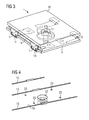
- FIG. 3 shows an overall perspective view of the heat shield element 1 according to the invention, which has a ceramic heat shield plate 10 and a metallic support plate 5.
- the ceramic heat shield plate 10 and the metallic support plate 5 are preferably held together by four retaining elements 7.
- the number of holders 7 may be reduced to at least two, one from each side.
- the holders 7 engage in the holder grooves 8 provided in the two oppositely facing edges of the heat shield plate 10.
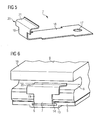
- FIGS. 5 and 6 A detail of this attachment is in the FIGS. 5 and 6 specified.
- the holder 7 of the same type as conventional for mounting the one-piece ceramic heat shield elements, z. As the adjacent, but are in contrast to a between the Heat shield plate 10 and the support structure 16 positioned metallic support plate 5 mounted.
- the through hole 11 serves as described above for inserting a narrow mounting tool to screw the fixing screw 2 in the support structure 16, where either a thread is present or a lock nut is positioned.
- FIG. 4 is a perspective view of the support structure 16, for example, a turbine engine, shown.
- the support structure 16 has parallel grooves 15, in which the one-piece ceramic heat shield elements are clamped one behind the other by means of the resilient metallic holder 7.
- the last piece of the heat shield is formed with the two-part heat shield element 1 according to the invention.
- a bore 22 is provided in the support structure 16 exactly at the location of the last heat shield element into which the protruding extension 3 of the metallic support plate 5 of the heat shield element is fitted.
- the two parallel arranged and correspondingly sized Vorstreckungen 13 are arranged in the parallel arranged, possibly widened grooves 15 of the support structure 16, so that the two-part heat shield element 1 according to the invention assumes a precisely predetermined position on the support structure 16.
- the support structure 16 may further include, in preferred embodiments, cooling apertures 23 connected to cooling air passages.
- the surface of the support structure 16 may be flat or curved. Furthermore, the curvature can be formed both convex and concave.
- the preferred determination of the two-part heat shield element 1 according to the invention is provided as a final element of the heat shield in a consequent mounting direction which follows substantially the normal to the surface of the support structure. However, it may be provided in terms of easier access and reduced effort to replace a defective heat shield element to provide multiple termination points in a heat shield row. Then not all heat shield elements in a row need to be removed to replace only a few elements.
- the two-part heat shield element 1 enables simple assembly by a person and only from one side of the installation if a thread device or a thread for the fastening screw 2 is provided in the support structure 16.
- FIG. 5 shows a holding element 7 in a perspective view.
- the retaining element 7 is preferably made of metal and comprises a fastening section 18, also called a retaining spring, with which the retaining element 7 can be fastened to a support structure 16 of a combustion chamber wall, for example the combustion chamber wall of a gas turbine plant.
- the holding elements 7 are guided on the support plate 5 in each case a groove 6 (see. Fig. 6 ).
- the groove 6 is designed so that it has the required width for inserting the shoes width only in the groove base. When pulling up the holding element 7 in the groove 6, this is supported on the narrow region of the groove 7, whereby a holding force holding the holding element 7 is mediated. The non-widened part of the attachment portion 18 can thereby be lifted freely in the groove 6.
- the attachment opening 17 in the shoe serves to fix all or some holding elements 7 in the groove, which can be done from the cold side of the support plate 5 by means of pins, Arretiermaden or screwing. Usually, a heat shield element is held on two opposite sides of two holding elements 7, that is, a total of four holding elements 7.
- the attachment portions 3 of the holding elements 7 arranged on the other side are not secured in a preferred embodiment, so that they can slide in order not to hinder the thermal expansion of the heat shield element.
- a holder head 20 is formed at that end of the retaining spring 18, which is opposite to the end with the attachment opening 17, a holder head 20 is formed.
- This holder head 20 has a section 19, which is angled substantially at right angles to the retaining spring 18, and a gripping section 21, which in turn is angled substantially perpendicular to the section 19.
- the gripping portion 21, also called the gripping tab, is used to engage in the groove of a heat shield element.
- a heat shield element can be clamped by engagement of gripping tabs 21 of holding elements 7, which are fixed to a support plate 5, in the holder grooves 8 opposite sides of the heat shield plate 10 with the support plate (see Fig. 6 ).
- FIG. 6 shows an enlarged partial perspective view of the heat shield element 1 according to the invention in the region of a holding element. 7
- the above-described ceramic heat shield plate 10 with the hot side 9 is in this case arranged on the arranged below it metallic support plate 5 and clamped with the retaining element 7 described in Figure 5.
- the groove 6 of the support plate 5 in this case has a wider groove bottom and a narrow portion 14 through which the retaining spring 18 of the retaining element 7 can escape while the shoe is retained with the mounting hole 17.
Landscapes
- Engineering & Computer Science (AREA)
- Chemical & Material Sciences (AREA)
- Combustion & Propulsion (AREA)
- Mechanical Engineering (AREA)
- General Engineering & Computer Science (AREA)
- Turbine Rotor Nozzle Sealing (AREA)
- Connection Of Plates (AREA)
- Shielding Devices Or Components To Electric Or Magnetic Fields (AREA)
- Cooling Or The Like Of Electrical Apparatus (AREA)
Claims (14)
- Elément ( 1 ) de bouclier thermique, pour un bouclier thermique ayant une pluralité d'éléments de bouclier thermique, montés au voisinage d'une structure ( 16 ) porteuse, l'élément ( 1 ) de bouclier thermique ayant un côté ( 9 ) chaud et un côté ( 4 ) froid, l'élément ( 1 ) de bouclier thermique ayant un plateau ( 10 ) formant le côté chaud et un plateau ( 5 ) support formant le côté froid, le plateau ( 10 ) du bouclier thermique pouvant être monté sur le plateau ( 5 ) support, dans lequel
pour le montage du plateau ( 10 ) du bouclier thermique sur le plateau ( 5 ) support, il est prévu au moins une perforation ( 11 ) dans le plateau ( 10 ) du bouclier thermique, la position de cette perforation ( 11 ), dans la surface du plateau ( 10 ) du bouclier thermique, étant prévue sensiblement comme une position symétrique et la dimension transversale de la perforation ( 11 ) étant prévue plus petite que le diamètre de la tête d'une vis ( 2 ) de fixation qui peut être vissée dans le plateau ( 5 ) support,
caractérisé en ce qu'il est prévu dans le plateau ( 5 ) support, en une position correspondant à la perforation ( 11 ) du plateau ( 10 ) du bouclier thermique, une cavité ( 12 ) ayant une perforation, dans laquelle la vis ( 2 ) de fixation peut être enfoncée, la tête de la vis ( 2 ) de fixation étant bloquée dans une chambre, formée par la cavité ( 12 ) et par le côté, tourné vers le plateau ( 5 ) support, du plateau ( 10 ) du bouclier thermique. - Elément ( 1 ) de bouclier thermique suivant la revendication 1,
caractérisé en ce que le plateau ( 10 ) du bouclier thermique formant le côté chaud est en un matériau fritté ou céramique, résistant à la chaleur. - Elément ( 1 ) de bouclier thermique suivant l'une des revendications précédentes,
caractérisé en ce que le plateau ( 5 ) support formant le côté froid est en un matériau métallique ou en un alliage métallique. - Elément ( 1 ) de bouclier thermique suivant l'une des revendications précédentes,
caractérisé en ce que le plateau ( 10 ) du bouclier thermique a respectivement une rainure ( 8 ) de retenue dans les deux bords latéraux opposés l'un à l'autre et éloignés l'un de l'autre, qui sont prévues pour l'accrochage des éléments ( 7 ) de retenue par des parties ( 21 ) de préhension. - Elément ( 1 ) de bouclier thermique suivant l'une des revendications précédentes,
caractérisé en ce que le plateau ( 5 ) support a au moins une rainure ( 6 ), qui a un fond de rainure élargi et une partie ( 14 ) étroite formant le côté ouvert de la rainure. - Elément ( 1 ) de bouclier thermique suivant l'une des revendications précédentes 4 à 5,
caractérisé en ce que le plateau ( 5 ) support et le plateau ( 10 ) du bouclier thermique sont cramponnés entre eux à l'aide d'au moins deux éléments ( 7 ) de retenue, l'élément ( 7 ) de retenue ayant des moyens d'accrochage dans les rainures ( 8 ) de retenue du plateau ( 10 ) du bouclier thermique et des moyens d'accrochage dans les rainures ( 6 ) du plateau ( 5 ) support. - Elément ( 1 ) de bouclier thermique suivant l'une des revendications précédentes 4 à 6,
caractérisé en ce que des moyens, constitués dans l'élément ( 7 ) de retenue, d'accrochage dans les rainures ( 8 ) de retenue du plateau ( 10 ) du bouclier thermique sont constitués sous la forme de parties ( 21 ) de préhension. - Elément ( 1 ) de bouclier thermique suivant l'une des revendications précédentes,
caractérisé en ce que les moyens constitués dans l'élément ( 7 ) de retenue d'accrochage dans les rainures ( 6 ) du plateau ( 5 ) support sont constitués sous la forme d'un sabot élargi, dont la largeur correspond à la largeur du fond élargi de la rainure ( 6 ) du plateau ( 5 ) de support. - Elément ( 1 ) de bouclier thermique suivant l'une des revendications précédentes,
caractérisé en ce que l'élément ( 7 ) de retenue a une partie ( 18 ) de fixation servant de ressort ( 18 ) de retenue, dont la largeur correspond à la largeur de la partie ( 14 ) étroite de la rainure ( 6 ) du plateau ( 5 ) support. - Elément ( 1 ) de bouclier thermique suivant l'une des revendications précédentes,
caractérisé en ce que l'épaisseur ( a ) du plateau ( 10 ) du bouclier thermique et l'épaisseur ( b ) du plateau ( 5 ) support donnent une épaisseur ( c ) totale, qui correspond à l'épaisseur d'un élément du bouclier thermique en céramique en une seule pièce. - Bouclier thermique sur une structure ( 16 ) porteuse, comportant une pluralité d'éléments de bouclier thermique ayant au moins un élément ( 1 ) de bouclier thermique, qui est prévu comme dernier élément de bouclier thermique fermant une rangée d'éléments de bouclier thermique voisins montés à l'avance,
caractérisé en ce que l'élément ( 1 ) de bouclier thermique est constitué suivant l'une des revendications précédentes. - Utilisation du bouclier thermique ayant au moins un élément de bouclier thermique suivant l'une des revendications précédentes, pour la fabrication d'une installation de combustion ou d'une turbomachine, la turbomachine étant réalisée sous la forme d'une turbine à gaz ou d'une turbine à combustible liquide.
- Procédé d'assemblage d'un élément ( 1 ) de bouclier thermique suivant l'une des revendications précédentes, caractérisé en ce que- on introduit la vis ( 2 ) de fixation dans la perforation prévue dans la cavité ( 12 ),- on cramponne le plateau ( 10 ) du bouclier thermique, à l'aide d'au moins deux éléments ( 7 ) de retenue, qui sont introduits, par leur sabot respectif, dans les rainures ( 6 ) du plateau ( 5 ) support, au plateau ( 5 ) support métallique, par accrochage, au moyen des parties ( 21 ) de préhension des éléments ( 7 ) de retenue, dans les rainures ( 8 ) de retenue prévues dans les bords éloignés l'un de l'autre du plateau ( 10 ) du bouclier thermique.
- Procédé suivant la revendication 13,
caractérisé en ce que
on fixe positivement un élément ( 7 ) de retenue au plateau ( 5 ) support, sur l'ouverture ( 17 ) de fixation, en laissant non fixé l'élément ( 7 ) de retenue opposé au moins à cet un élément ( 7 ) de retenue fixé.
Priority Applications (1)
| Application Number | Priority Date | Filing Date | Title |
|---|---|---|---|
| EP09784070.6A EP2409083B1 (fr) | 2009-03-17 | 2009-12-02 | Élément de protection thermique d'un bouclier thermique |
Applications Claiming Priority (3)
| Application Number | Priority Date | Filing Date | Title |
|---|---|---|---|
| EP09155390A EP2236928A1 (fr) | 2009-03-17 | 2009-03-17 | Elément de bouclier thermique |
| EP09784070.6A EP2409083B1 (fr) | 2009-03-17 | 2009-12-02 | Élément de protection thermique d'un bouclier thermique |
| PCT/EP2009/066243 WO2010105709A2 (fr) | 2009-03-17 | 2009-12-02 | Élément de protection thermique d'un bouclier thermique |
Publications (2)
| Publication Number | Publication Date |
|---|---|
| EP2409083A2 EP2409083A2 (fr) | 2012-01-25 |
| EP2409083B1 true EP2409083B1 (fr) | 2015-07-29 |
Family
ID=40886950
Family Applications (2)
| Application Number | Title | Priority Date | Filing Date |
|---|---|---|---|
| EP09155390A Withdrawn EP2236928A1 (fr) | 2009-03-17 | 2009-03-17 | Elément de bouclier thermique |
| EP09784070.6A Not-in-force EP2409083B1 (fr) | 2009-03-17 | 2009-12-02 | Élément de protection thermique d'un bouclier thermique |
Family Applications Before (1)
| Application Number | Title | Priority Date | Filing Date |
|---|---|---|---|
| EP09155390A Withdrawn EP2236928A1 (fr) | 2009-03-17 | 2009-03-17 | Elément de bouclier thermique |
Country Status (5)
| Country | Link |
|---|---|
| US (1) | US20110318531A1 (fr) |
| EP (2) | EP2236928A1 (fr) |
| CN (2) | CN103759293A (fr) |
| RU (1) | RU2515692C2 (fr) |
| WO (1) | WO2010105709A2 (fr) |
Cited By (1)
| Publication number | Priority date | Publication date | Assignee | Title |
|---|---|---|---|---|
| EP3309456A1 (fr) | 2016-10-13 | 2018-04-18 | Siemens Aktiengesellschaft | Écran thermique avec carreau et support |
Families Citing this family (18)
| Publication number | Priority date | Publication date | Assignee | Title |
|---|---|---|---|---|
| DE102010015263B4 (de) * | 2010-04-15 | 2013-06-27 | Leybold Optics Gmbh | Hitzeschild in einer thermischen Bearbeitungskammer und Verfahren zu seiner Herstellung |
| US20130305517A1 (en) * | 2012-05-16 | 2013-11-21 | Laith Anthony Vincent | Captured threaded connector system and method for mechanically coupling components |
| EP2711630A1 (fr) * | 2012-09-21 | 2014-03-26 | Siemens Aktiengesellschaft | Dispositif de refroidissement d'une structure porteuse d'un bouclier thermique et bouclier thermique |
| ITMI20122104A1 (it) * | 2012-12-10 | 2014-06-11 | Ansaldo Energia Spa | Struttura di supporto per piastrelle termoisolanti di camere di combustione di turbine a gas, modulo termoisolante e camera di combustione di turbina a gas |
| EP2762782A1 (fr) * | 2013-02-05 | 2014-08-06 | Siemens Aktiengesellschaft | Élément de retenue pour maintenir une brique de protection thermique sur une structure porteuse |
| ITMI20131115A1 (it) * | 2013-07-03 | 2015-01-04 | Ansaldo Energia Spa | Piastrella per il rivestimento di camere di combustione, in particolare di impianti per la produzione di energia elettrica a turbina a gas, e camera di combustione comprendente detta piastrella |
| EP3033509B1 (fr) * | 2013-08-15 | 2019-05-15 | United Technologies Corporation | Turbine à gas comprenant un panneau de protection et support à cet effet |
| EP3043113B1 (fr) * | 2015-01-12 | 2018-05-23 | A.S.EN. Ansaldo Sviluppo Energia S.r.l. | Dispositif de fixation pour carreau thermo-isolant de chambre de combustion de turbine à gaz |
| CN104654359B (zh) * | 2015-02-13 | 2017-12-19 | 北京华清燃气轮机与煤气化联合循环工程技术有限公司 | 一种燃烧室预混合燃料喷嘴的引流结构 |
| CN108474284B (zh) | 2015-12-28 | 2020-11-27 | 莱多公司 | 具有保持特征的热屏蔽件 |
| DE102016114177B4 (de) * | 2016-04-15 | 2023-11-23 | Jünger+Gräter GmbH | Feuerfestschutzsegment |
| EP3211307B1 (fr) | 2016-02-26 | 2019-06-05 | Jünger + Gräter GmbH Feuerfestbau | Élément protecteur réfractaire |
| DE102016103443B4 (de) * | 2016-02-26 | 2022-04-28 | Jünger+Gräter GmbH | Feuerfestschutzsegment |
| WO2019217839A1 (fr) | 2018-05-10 | 2019-11-14 | Blue Origin, Llc | Système de protection thermique à haute température pour fusées, et procédés associés |
| US11667408B2 (en) | 2018-06-12 | 2023-06-06 | Blue Origin, Llc | Metal encapsulated ceramic tile thermal insulation, and associated systems and methods |
| DE102018213925A1 (de) | 2018-08-17 | 2020-02-20 | Rolls-Royce Deutschland Ltd & Co Kg | Brennkammerbaugruppe mit Schindelbauteil und Positonierungshilfe |
| DE102019200593A1 (de) * | 2019-01-17 | 2020-07-23 | Siemens Aktiengesellschaft | Brennkammer |
| CN113074386B (zh) * | 2021-03-17 | 2022-08-16 | 中国航发动力股份有限公司 | 一种隔热屏安装用辅助装置及隔热屏安装方法 |
Family Cites Families (13)
| Publication number | Priority date | Publication date | Assignee | Title |
|---|---|---|---|---|
| WO1989012789A1 (fr) * | 1988-06-13 | 1989-12-28 | Siemens Aktiengesellschaft | Bouclier thermique n'exigeant que peu de fluide de refroidissement |
| SU1643878A1 (ru) * | 1989-01-03 | 1991-04-23 | Производственное Объединение Атомного Турбостроения "Харьковский Турбинный Завод" Им.С.М.Кирова | Кольцева камера сгорани газотурбинного двигател |
| ES2073182T3 (es) | 1990-11-29 | 1995-08-01 | Siemens Ag | Escudo termico ceramico en una estructura portante. |
| DE19502730A1 (de) * | 1995-01-28 | 1996-08-01 | Abb Management Ag | Keramische Auskleidung |
| EP0895028B1 (fr) * | 1997-07-28 | 2002-03-06 | Alstom | Garniture céramique |
| DE59706557D1 (de) * | 1997-07-28 | 2002-04-11 | Alstom | Keramische Auskleidung |
| DE19825546C1 (de) * | 1998-06-08 | 1999-08-26 | Didier Werke Ag | Einrichtung zum Befestigen von Auskleidungsplatten |
| DE10003728A1 (de) * | 2000-01-28 | 2001-08-09 | Siemens Ag | Hitzeschildanordnung für eine Heißgas führende Komponente, insbesondere für Strukturteile von Gasturbinen |
| US7291407B2 (en) * | 2002-09-06 | 2007-11-06 | Siemens Power Generation, Inc. | Ceramic material having ceramic matrix composite backing and method of manufacturing |
| EP1533572A1 (fr) * | 2003-11-24 | 2005-05-25 | Siemens Aktiengesellschaft | Chambre de combustion pour turbine à gaz et turbine à gaz |
| WO2006058629A1 (fr) * | 2004-12-01 | 2006-06-08 | Siemens Aktiengesellschaft | Element ecran thermique, procede et moule pour sa fabrication, revetement a gaz chaud et chambre de combustion |
| EP1701095B1 (fr) | 2005-02-07 | 2012-01-18 | Siemens Aktiengesellschaft | Ecran thermique |
| WO2008017550A1 (fr) * | 2006-08-07 | 2008-02-14 | Alstom Technology Ltd | Chambre de combustion d'une installation de combustion |
-
2009
- 2009-03-17 EP EP09155390A patent/EP2236928A1/fr not_active Withdrawn
- 2009-12-02 RU RU2011141839/06A patent/RU2515692C2/ru not_active IP Right Cessation
- 2009-12-02 US US13/255,574 patent/US20110318531A1/en not_active Abandoned
- 2009-12-02 EP EP09784070.6A patent/EP2409083B1/fr not_active Not-in-force
- 2009-12-02 WO PCT/EP2009/066243 patent/WO2010105709A2/fr not_active Ceased
- 2009-12-02 CN CN201410058197.4A patent/CN103759293A/zh not_active Withdrawn
- 2009-12-02 CN CN200980158149.XA patent/CN102356277B/zh not_active Expired - Fee Related
Cited By (2)
| Publication number | Priority date | Publication date | Assignee | Title |
|---|---|---|---|---|
| EP3309456A1 (fr) | 2016-10-13 | 2018-04-18 | Siemens Aktiengesellschaft | Écran thermique avec carreau et support |
| WO2018068980A1 (fr) | 2016-10-13 | 2018-04-19 | Siemens Aktiengesellschaft | Élément d'écran thermique à carreau et support |
Also Published As
| Publication number | Publication date |
|---|---|
| US20110318531A1 (en) | 2011-12-29 |
| CN103759293A (zh) | 2014-04-30 |
| WO2010105709A3 (fr) | 2011-04-14 |
| RU2011141839A (ru) | 2013-04-27 |
| CN102356277A (zh) | 2012-02-15 |
| WO2010105709A2 (fr) | 2010-09-23 |
| CN102356277B (zh) | 2014-10-22 |
| EP2409083A2 (fr) | 2012-01-25 |
| EP2236928A1 (fr) | 2010-10-06 |
| RU2515692C2 (ru) | 2014-05-20 |
Similar Documents
| Publication | Publication Date | Title |
|---|---|---|
| EP2236928A1 (fr) | Elément de bouclier thermique | |
| EP2270395B1 (fr) | Agencement d'élément de bouclier thermique et procédé de montage d'un élément de bouclier thermique | |
| EP0558540B1 (fr) | Ecran thermique en ceramique monte sur une structure portante | |
| EP1701095B1 (fr) | Ecran thermique | |
| EP2992270B1 (fr) | Bouclier thermique | |
| EP2440851B1 (fr) | Agencement d'élément d'un bouclier thermique doté d'un moyen de guidance de vis et procédé de montage d'un élément d'un bouclier thermique | |
| EP1247602B1 (fr) | Procédé pour la fabrication d'une aube de turbine | |
| EP0321825B1 (fr) | Rangée d'aubes rotoriques pour traversée axiale pour compresseurs ou turbines | |
| DE10155420A1 (de) | Hitzeschildanordnung mit Dichtungselement | |
| EP2596290B1 (fr) | Élément de protection thermique | |
| EP2823152A1 (fr) | Aube mobile de turbine et section axiale de rotor pour une turbine à gaz | |
| EP2407641A1 (fr) | Elément d'étanchéité pour étanchéifier une fente et agencement d'étanchéité | |
| EP1260767A1 (fr) | Ensemble bouclier thermique pour un composant acheminant un gaz chaud, notamment pour des pièces de structure de turbines à gaz, ainsi que le procédé de fabrication d'un tel ensemble | |
| DE60023884T2 (de) | Vorrichtung zur regelung der luftströmung in einer turbinenschaufel | |
| EP4078031B1 (fr) | Chambre de combustion avec boucliers thermiques | |
| EP2394763A1 (fr) | Plaque de coupe et lame de scie dotée d'une multitude de telles plaques de coupe | |
| EP3132201B1 (fr) | Élément de bouclier thermique révêtu latéralement avec refroidissement par impact aux surfaces non-couverts | |
| EP3762586B1 (fr) | Paroi de composant à gaz chaud | |
| EP2409082B1 (fr) | Dispositif destiné au montage d'un élément de bouclier thermique | |
| WO2011117395A1 (fr) | Composant doté d'une paroi extérieure pouvant être exposée à un gaz chaud d'une turbine à gaz et procédé de fabrication d'un tel composant | |
| EP3894749B1 (fr) | Chambre de combustion | |
| DE102013214403B4 (de) | Grundplatte für einen Fahrzeugwärmetauscher, Verfahren zu ihrer Herstellung, Wärmetauscher und Ölfiltermodul | |
| EP3839347A1 (fr) | Carreau de bouclier thermique d'une chambre de combustion | |
| DE20011315U1 (de) | Strahlungsheizkörper für Kochfelder | |
| DE102015206033A1 (de) | Steinhalter |
Legal Events
| Date | Code | Title | Description |
|---|---|---|---|
| PUAI | Public reference made under article 153(3) epc to a published international application that has entered the european phase |
Free format text: ORIGINAL CODE: 0009012 |
|
| 17P | Request for examination filed |
Effective date: 20110913 |
|
| AK | Designated contracting states |
Kind code of ref document: A2 Designated state(s): AT BE BG CH CY CZ DE DK EE ES FI FR GB GR HR HU IE IS IT LI LT LU LV MC MK MT NL NO PL PT RO SE SI SK SM TR |
|
| DAX | Request for extension of the european patent (deleted) | ||
| RAP1 | Party data changed (applicant data changed or rights of an application transferred) |
Owner name: SIEMENS AKTIENGESELLSCHAFT |
|
| GRAP | Despatch of communication of intention to grant a patent |
Free format text: ORIGINAL CODE: EPIDOSNIGR1 |
|
| INTG | Intention to grant announced |
Effective date: 20150303 |
|
| GRAS | Grant fee paid |
Free format text: ORIGINAL CODE: EPIDOSNIGR3 |
|
| GRAA | (expected) grant |
Free format text: ORIGINAL CODE: 0009210 |
|
| AK | Designated contracting states |
Kind code of ref document: B1 Designated state(s): AT BE BG CH CY CZ DE DK EE ES FI FR GB GR HR HU IE IS IT LI LT LU LV MC MK MT NL NO PL PT RO SE SI SK SM TR |
|
| REG | Reference to a national code |
Ref country code: GB Ref legal event code: FG4D Free format text: NOT ENGLISH |
|
| REG | Reference to a national code |
Ref country code: CH Ref legal event code: EP |
|
| REG | Reference to a national code |
Ref country code: AT Ref legal event code: REF Ref document number: 739633 Country of ref document: AT Kind code of ref document: T Effective date: 20150815 |
|
| REG | Reference to a national code |
Ref country code: IE Ref legal event code: FG4D Free format text: LANGUAGE OF EP DOCUMENT: GERMAN |
|
| REG | Reference to a national code |
Ref country code: DE Ref legal event code: R096 Ref document number: 502009011341 Country of ref document: DE |
|
| REG | Reference to a national code |
Ref country code: LT Ref legal event code: MG4D |
|
| REG | Reference to a national code |
Ref country code: NL Ref legal event code: MP Effective date: 20150729 |
|
| PG25 | Lapsed in a contracting state [announced via postgrant information from national office to epo] |
Ref country code: LT Free format text: LAPSE BECAUSE OF FAILURE TO SUBMIT A TRANSLATION OF THE DESCRIPTION OR TO PAY THE FEE WITHIN THE PRESCRIBED TIME-LIMIT Effective date: 20150729 Ref country code: GR Free format text: LAPSE BECAUSE OF FAILURE TO SUBMIT A TRANSLATION OF THE DESCRIPTION OR TO PAY THE FEE WITHIN THE PRESCRIBED TIME-LIMIT Effective date: 20151030 Ref country code: LV Free format text: LAPSE BECAUSE OF FAILURE TO SUBMIT A TRANSLATION OF THE DESCRIPTION OR TO PAY THE FEE WITHIN THE PRESCRIBED TIME-LIMIT Effective date: 20150729 Ref country code: NO Free format text: LAPSE BECAUSE OF FAILURE TO SUBMIT A TRANSLATION OF THE DESCRIPTION OR TO PAY THE FEE WITHIN THE PRESCRIBED TIME-LIMIT Effective date: 20151029 Ref country code: FI Free format text: LAPSE BECAUSE OF FAILURE TO SUBMIT A TRANSLATION OF THE DESCRIPTION OR TO PAY THE FEE WITHIN THE PRESCRIBED TIME-LIMIT Effective date: 20150729 |
|
| PG25 | Lapsed in a contracting state [announced via postgrant information from national office to epo] |
Ref country code: ES Free format text: LAPSE BECAUSE OF FAILURE TO SUBMIT A TRANSLATION OF THE DESCRIPTION OR TO PAY THE FEE WITHIN THE PRESCRIBED TIME-LIMIT Effective date: 20150729 Ref country code: IS Free format text: LAPSE BECAUSE OF FAILURE TO SUBMIT A TRANSLATION OF THE DESCRIPTION OR TO PAY THE FEE WITHIN THE PRESCRIBED TIME-LIMIT Effective date: 20151129 Ref country code: SE Free format text: LAPSE BECAUSE OF FAILURE TO SUBMIT A TRANSLATION OF THE DESCRIPTION OR TO PAY THE FEE WITHIN THE PRESCRIBED TIME-LIMIT Effective date: 20150729 Ref country code: HR Free format text: LAPSE BECAUSE OF FAILURE TO SUBMIT A TRANSLATION OF THE DESCRIPTION OR TO PAY THE FEE WITHIN THE PRESCRIBED TIME-LIMIT Effective date: 20150729 Ref country code: PT Free format text: LAPSE BECAUSE OF FAILURE TO SUBMIT A TRANSLATION OF THE DESCRIPTION OR TO PAY THE FEE WITHIN THE PRESCRIBED TIME-LIMIT Effective date: 20151130 Ref country code: PL Free format text: LAPSE BECAUSE OF FAILURE TO SUBMIT A TRANSLATION OF THE DESCRIPTION OR TO PAY THE FEE WITHIN THE PRESCRIBED TIME-LIMIT Effective date: 20150729 |
|
| PG25 | Lapsed in a contracting state [announced via postgrant information from national office to epo] |
Ref country code: NL Free format text: LAPSE BECAUSE OF FAILURE TO SUBMIT A TRANSLATION OF THE DESCRIPTION OR TO PAY THE FEE WITHIN THE PRESCRIBED TIME-LIMIT Effective date: 20150729 |
|
| PG25 | Lapsed in a contracting state [announced via postgrant information from national office to epo] |
Ref country code: CZ Free format text: LAPSE BECAUSE OF FAILURE TO SUBMIT A TRANSLATION OF THE DESCRIPTION OR TO PAY THE FEE WITHIN THE PRESCRIBED TIME-LIMIT Effective date: 20150729 Ref country code: SK Free format text: LAPSE BECAUSE OF FAILURE TO SUBMIT A TRANSLATION OF THE DESCRIPTION OR TO PAY THE FEE WITHIN THE PRESCRIBED TIME-LIMIT Effective date: 20150729 Ref country code: EE Free format text: LAPSE BECAUSE OF FAILURE TO SUBMIT A TRANSLATION OF THE DESCRIPTION OR TO PAY THE FEE WITHIN THE PRESCRIBED TIME-LIMIT Effective date: 20150729 Ref country code: DK Free format text: LAPSE BECAUSE OF FAILURE TO SUBMIT A TRANSLATION OF THE DESCRIPTION OR TO PAY THE FEE WITHIN THE PRESCRIBED TIME-LIMIT Effective date: 20150729 |
|
| REG | Reference to a national code |
Ref country code: DE Ref legal event code: R097 Ref document number: 502009011341 Country of ref document: DE |
|
| PG25 | Lapsed in a contracting state [announced via postgrant information from national office to epo] |
Ref country code: RO Free format text: LAPSE BECAUSE OF FAILURE TO SUBMIT A TRANSLATION OF THE DESCRIPTION OR TO PAY THE FEE WITHIN THE PRESCRIBED TIME-LIMIT Effective date: 20150729 Ref country code: BE Free format text: LAPSE BECAUSE OF NON-PAYMENT OF DUE FEES Effective date: 20151231 |
|
| PLBE | No opposition filed within time limit |
Free format text: ORIGINAL CODE: 0009261 |
|
| STAA | Information on the status of an ep patent application or granted ep patent |
Free format text: STATUS: NO OPPOSITION FILED WITHIN TIME LIMIT |
|
| 26N | No opposition filed |
Effective date: 20160502 |
|
| PG25 | Lapsed in a contracting state [announced via postgrant information from national office to epo] |
Ref country code: MC Free format text: LAPSE BECAUSE OF FAILURE TO SUBMIT A TRANSLATION OF THE DESCRIPTION OR TO PAY THE FEE WITHIN THE PRESCRIBED TIME-LIMIT Effective date: 20150729 Ref country code: LU Free format text: LAPSE BECAUSE OF FAILURE TO SUBMIT A TRANSLATION OF THE DESCRIPTION OR TO PAY THE FEE WITHIN THE PRESCRIBED TIME-LIMIT Effective date: 20151202 |
|
| REG | Reference to a national code |
Ref country code: CH Ref legal event code: PL |
|
| GBPC | Gb: european patent ceased through non-payment of renewal fee |
Effective date: 20151202 |
|
| PG25 | Lapsed in a contracting state [announced via postgrant information from national office to epo] |
Ref country code: SI Free format text: LAPSE BECAUSE OF FAILURE TO SUBMIT A TRANSLATION OF THE DESCRIPTION OR TO PAY THE FEE WITHIN THE PRESCRIBED TIME-LIMIT Effective date: 20150729 |
|
| REG | Reference to a national code |
Ref country code: IE Ref legal event code: MM4A |
|
| REG | Reference to a national code |
Ref country code: FR Ref legal event code: ST Effective date: 20160831 |
|
| PG25 | Lapsed in a contracting state [announced via postgrant information from national office to epo] |
Ref country code: CH Free format text: LAPSE BECAUSE OF NON-PAYMENT OF DUE FEES Effective date: 20151231 Ref country code: IE Free format text: LAPSE BECAUSE OF NON-PAYMENT OF DUE FEES Effective date: 20151202 Ref country code: GB Free format text: LAPSE BECAUSE OF NON-PAYMENT OF DUE FEES Effective date: 20151202 Ref country code: LI Free format text: LAPSE BECAUSE OF NON-PAYMENT OF DUE FEES Effective date: 20151231 |
|
| PG25 | Lapsed in a contracting state [announced via postgrant information from national office to epo] |
Ref country code: FR Free format text: LAPSE BECAUSE OF NON-PAYMENT OF DUE FEES Effective date: 20151231 |
|
| REG | Reference to a national code |
Ref country code: AT Ref legal event code: MM01 Ref document number: 739633 Country of ref document: AT Kind code of ref document: T Effective date: 20151202 |
|
| PG25 | Lapsed in a contracting state [announced via postgrant information from national office to epo] |
Ref country code: BG Free format text: LAPSE BECAUSE OF FAILURE TO SUBMIT A TRANSLATION OF THE DESCRIPTION OR TO PAY THE FEE WITHIN THE PRESCRIBED TIME-LIMIT Effective date: 20150729 Ref country code: SM Free format text: LAPSE BECAUSE OF FAILURE TO SUBMIT A TRANSLATION OF THE DESCRIPTION OR TO PAY THE FEE WITHIN THE PRESCRIBED TIME-LIMIT Effective date: 20150729 Ref country code: AT Free format text: LAPSE BECAUSE OF NON-PAYMENT OF DUE FEES Effective date: 20151202 Ref country code: HU Free format text: LAPSE BECAUSE OF FAILURE TO SUBMIT A TRANSLATION OF THE DESCRIPTION OR TO PAY THE FEE WITHIN THE PRESCRIBED TIME-LIMIT; INVALID AB INITIO Effective date: 20091202 |
|
| PG25 | Lapsed in a contracting state [announced via postgrant information from national office to epo] |
Ref country code: CY Free format text: LAPSE BECAUSE OF FAILURE TO SUBMIT A TRANSLATION OF THE DESCRIPTION OR TO PAY THE FEE WITHIN THE PRESCRIBED TIME-LIMIT Effective date: 20150729 |
|
| PG25 | Lapsed in a contracting state [announced via postgrant information from national office to epo] |
Ref country code: MT Free format text: LAPSE BECAUSE OF FAILURE TO SUBMIT A TRANSLATION OF THE DESCRIPTION OR TO PAY THE FEE WITHIN THE PRESCRIBED TIME-LIMIT Effective date: 20150729 Ref country code: TR Free format text: LAPSE BECAUSE OF FAILURE TO SUBMIT A TRANSLATION OF THE DESCRIPTION OR TO PAY THE FEE WITHIN THE PRESCRIBED TIME-LIMIT Effective date: 20150729 |
|
| PGFP | Annual fee paid to national office [announced via postgrant information from national office to epo] |
Ref country code: DE Payment date: 20180219 Year of fee payment: 9 |
|
| PG25 | Lapsed in a contracting state [announced via postgrant information from national office to epo] |
Ref country code: MK Free format text: LAPSE BECAUSE OF FAILURE TO SUBMIT A TRANSLATION OF THE DESCRIPTION OR TO PAY THE FEE WITHIN THE PRESCRIBED TIME-LIMIT Effective date: 20150729 |
|
| PGFP | Annual fee paid to national office [announced via postgrant information from national office to epo] |
Ref country code: IT Payment date: 20181220 Year of fee payment: 10 |
|
| REG | Reference to a national code |
Ref country code: DE Ref legal event code: R119 Ref document number: 502009011341 Country of ref document: DE |
|
| PG25 | Lapsed in a contracting state [announced via postgrant information from national office to epo] |
Ref country code: DE Free format text: LAPSE BECAUSE OF NON-PAYMENT OF DUE FEES Effective date: 20190702 |
|
| PG25 | Lapsed in a contracting state [announced via postgrant information from national office to epo] |
Ref country code: IT Free format text: LAPSE BECAUSE OF NON-PAYMENT OF DUE FEES Effective date: 20191202 |