EP2409758A1 - Structure dotée d'une membrane de séparation zéolitique, procédé de production associé, procédé de séparation de fluides mixtes et dispositif de séparation de fluides mixtes - Google Patents
Structure dotée d'une membrane de séparation zéolitique, procédé de production associé, procédé de séparation de fluides mixtes et dispositif de séparation de fluides mixtes Download PDFInfo
- Publication number
- EP2409758A1 EP2409758A1 EP10753376A EP10753376A EP2409758A1 EP 2409758 A1 EP2409758 A1 EP 2409758A1 EP 10753376 A EP10753376 A EP 10753376A EP 10753376 A EP10753376 A EP 10753376A EP 2409758 A1 EP2409758 A1 EP 2409758A1
- Authority
- EP
- European Patent Office
- Prior art keywords
- membrane
- zeolite
- zeolite membrane
- permeation
- separation
- Prior art date
- Legal status (The legal status is an assumption and is not a legal conclusion. Google has not performed a legal analysis and makes no representation as to the accuracy of the status listed.)
- Ceased
Links
Images



Classifications
-
- B—PERFORMING OPERATIONS; TRANSPORTING
- B01—PHYSICAL OR CHEMICAL PROCESSES OR APPARATUS IN GENERAL
- B01D—SEPARATION
- B01D53/00—Separation of gases or vapours; Recovering vapours of volatile solvents from gases; Chemical or biological purification of waste gases, e.g. engine exhaust gases, smoke, fumes, flue gases, aerosols
- B01D53/22—Separation of gases or vapours; Recovering vapours of volatile solvents from gases; Chemical or biological purification of waste gases, e.g. engine exhaust gases, smoke, fumes, flue gases, aerosols by diffusion
- B01D53/228—Separation of gases or vapours; Recovering vapours of volatile solvents from gases; Chemical or biological purification of waste gases, e.g. engine exhaust gases, smoke, fumes, flue gases, aerosols by diffusion characterised by specific membranes
-
- B—PERFORMING OPERATIONS; TRANSPORTING
- B01—PHYSICAL OR CHEMICAL PROCESSES OR APPARATUS IN GENERAL
- B01D—SEPARATION
- B01D63/00—Apparatus in general for separation processes using semi-permeable membranes
- B01D63/06—Tubular membrane modules
- B01D63/066—Tubular membrane modules with a porous block having membrane coated passages
-
- B—PERFORMING OPERATIONS; TRANSPORTING
- B01—PHYSICAL OR CHEMICAL PROCESSES OR APPARATUS IN GENERAL
- B01D—SEPARATION
- B01D67/00—Processes specially adapted for manufacturing semi-permeable membranes for separation processes or apparatus
- B01D67/0039—Inorganic membrane manufacture
- B01D67/0051—Inorganic membrane manufacture by controlled crystallisation, e,.g. hydrothermal growth
-
- B—PERFORMING OPERATIONS; TRANSPORTING
- B01—PHYSICAL OR CHEMICAL PROCESSES OR APPARATUS IN GENERAL
- B01D—SEPARATION
- B01D71/00—Semi-permeable membranes for separation processes or apparatus characterised by the material; Manufacturing processes specially adapted therefor
- B01D71/02—Inorganic material
- B01D71/028—Molecular sieves
- B01D71/0281—Zeolites
-
- B—PERFORMING OPERATIONS; TRANSPORTING
- B01—PHYSICAL OR CHEMICAL PROCESSES OR APPARATUS IN GENERAL
- B01D—SEPARATION
- B01D2323/00—Details relating to membrane preparation
- B01D2323/42—Details of membrane preparation apparatus
Definitions
- the present invention relates to a zeolite separation membrane-provided article for separating a fluid, a method for producing the same, a method for separating mixed fluids, and a device for separating mixed fluids.
- a zeolite membrane, a carbon membrane, a titania membrane, and the like as separation membranes with being disposed on a surface of a porous substrate.
- a separation membrane-provided article where a zeolite membrane is disposed as a separation membrane at a predetermined position of a porous substrate.
- Patent Documents 1 and 2 As membrane separation using a MFI type zeolite membrane, there is disclosed ethanol separation from a mixed liquid of ethanol and water (Patent Documents 1 and 2)
- Patent Document 3 and Non Patent Document 1 disclose separation of a xylene isomer, where para-xylene is selectively permeated to block ortho-xylene and meta-xylene.
- Patent Document 4 discloses separation of side-chain hydrocarbon from linear-chain hydrocarbon
- Patent Document 5 discloses separation of aromatic hydrocarbon from linear-chain hydrocarbon
- Patent Documents 4 and 5 disclose usage of pores or gaps larger than the pores inherent to zeolite crystals as a measurement for solving the problem.
- Non Patent Documents 2 and 3 disclose that, in a zeolite membrane having pores larger than the pores inherent to zeolite crystals, it is possible to separate side chain butane (isobutane) from liner chain butane (normal butane) which is a hydrocarbon isomer having a carbon number of 4.
- separation of gas or liquid by a membrane is based on the sieving of molecules by pores of the membrane (molecular sieve effect) or the difference in affinity between the membrane and molecules (adsorption effect). Therefore, for separation of gas or liquid, the relation between the size of the pores of the membrane and the size of each of the molecules permeating the membrane is important.
- the permeability improves.
- the molecular sieve effect and the adsorption effect are lost, and separability is deteriorated.
- the pores of the membrane are too small for gas or liquid as a target for separation, nothing permeates the membrane. Or, permeability is deteriorated though separability improves.
- Patent Documents 4 and 5 disclose the use of gaps or pores larger than the pores inherent to zeolite crystals as a measure for achieving both permeability and separability in a zeolite membrane.
- Japanese Document 4 discloses separation of linear chain hydrocarbon having carbon numbers of 4 and 5 from side chain hydrocarbon by a zeolite membrane having pores of 1 to 10 nm besides the pores of 1 nm or less inherent to zeolite crystals.
- Patent Document 5 discloses separation of aromatic hydrocarbon from liner chain hydrocarbon having a carbon number of 7, where pores of zeolite and/or a grain boundary are/is used.
- Non Patent Document 4 gas or liquid can be separated by the adsorption effect even when pores having large diameters in comparison with a molecule diameter of a permeable component and a non- permeable component.
- the size of the pore exhibiting an adsorption effect depends on the target to be separated.
- separation is hard if the membrane has a relatively large pore.
- separation is hard if the membrane has a relatively large pore.
- An example of the former case is a linear chain hydrocarbon having high carbon number, in particular, a carbon number of 6 or more and side chain hydrocarbon.
- Examples of the latter case are alcohol and water and a linear chain hydrocarbon and inorganic gas.
- the present invention aims to provide a zeolite separation membrane-provided article being capable of achieving both high permeability and high separability for components with a small difference in adsorption properties, such as liner chain hydrocarbon having a carbon number of 6 or more and side chain hydrocarbon, or a component having a smaller molecular diameter, such as alcohol and water, linear hydrocarbon and inorganic gas.
- adsorption properties such as liner chain hydrocarbon having a carbon number of 6 or more and side chain hydrocarbon, or a component having a smaller molecular diameter, such as alcohol and water, linear hydrocarbon and inorganic gas.
- a zeolite separation membrane-provided article provided with pores whose sizes are controlled in an appropriate range, high permeation flux and high separation coefficient can be obtained even for components with small difference in adsorption properties or components having a smaller molecular diameter than the pores besides the pores inherent to zeolite crystals. That is, according to the present invention, there is provided a zeolite separation membrane-provided article, a method for producing the same, a method for separating mixed fluids, and a device for separating mixed fluids.
- a zeolite membrane-provided article provided with a zeolite membrane having an N 2 gas permeation speed at room temperature of 1.0 ⁇ 10 -6 mol ⁇ m -2 ⁇ s -1 ⁇ Pa -1 or more and a permeation speed ratio of 1,3,5-trimethylbenzene/N 2 at room temperature of 0.17 or more and being free from dyeing caused by the impregnation with Rhodamine B.
- a zeolite membrane-provided article provided with a zeolite membrane where pore sizes of pores inherent to zeolite crystals are 0.76 nm or less and where pore sizes of pores other than the pores inherent in zeolite crystals are 0.76 to 2 nm.
- a method for producing a zeolite membrane-provided article comprising: a seed crystal-forming step of putting a seeding sol containing silica, water, and a structure directing agent and a support in a pressure resistant container in a state that the support is immersed in the seeding sol, followed by heating the inside of the pressure resistant container to form zeolite seed crystals on a surface of the support; a membrane-forming step of growing the zeolite seed crystal to form a dense zeolite membrane containing the structure directing agent on the surface of the support; and a removal step of removing the structure directing agent from the dense zeolite membrane; wherein the removal treatment in the removal step is performed by a heat treatment, the heat treatment is performed in a maximum temperature range of 400 to 1000°C and includes a temperature rise step at a temperature rise speed of 0.1°C/min.
- the zeolite membrane-provided article is provided with a zeolite membrane having an N 2 gas permeation speed at room temperature of 1.0 ⁇ 10 -6 mol ⁇ m -2 ⁇ s -1 ⁇ Pa -1 or more and a permeation speed ratio of 1,3,5-trimethylbenzene/N 2 at room temperature of 0.17 or more and being free from dyeing caused by the impregnation with Rhodamine B.
- a method for separating a mixed fluid wherein a mixed fluid of two or more different components is separated by using a zeolite membrane-provided article according to any one of [1] to [6].
- a mixed fluid separation device having a zeolite separation membrane-provided article according to any one of [1] to [6] and comprising: a separation section for separating a raw material side space from a permeation side space by a porous substrate, a supply section for supplying a mixed fluid to the raw material side space, a permeation collection section for collecting permeation liquid and/or permeation gas having penetrated the zeolite membrane.
- a zeolite separation membrane-provided article of the present invention has gaps or pores of 0.76 nm or more and about 2 nm or less, which are larger than the pores inherent to zeolite crystals. Therefore, the zeolite separation membrane-provided article can achieve both high permeability and high separability in the case of separation of side chain hydrocarbon from linear chain hydrocarbon, aromatic hydrocarbon from linear chain hydrocarbon, water from alcohol, or inorganic gas from linear chain saturated hydrocarbon.
- a zeolite separation membrane-provided article of the present invention has an N 2 gas permeation speed at room temperature of 1.0 ⁇ 10 -6 mol ⁇ m -2 ⁇ s -1 ⁇ Pa -1 or more and a permeation speed ratio of 1,3,5-trimethylbenzene/N 2 at room temperature of 0.17 or more and is free from dyeing caused by the impregnation with Rhodamine B.
- pore sizes of pores inherent in zeolite crystals are 0.76 nm or less and where pore sizes of pores other than the pores inherent to zeolite crystals are 0.76 to 2 nm.
- the zeolite membrane is formed on a surface of a support of a porous material.
- the zeolite membrane is preferably a MFI membrane, more preferably a silicalite membrane.
- a zeolite separation membrane-provided article of the present invention can be used for separation of a mixed fluid of two or more different components.
- the article has gaps or pores larger (0.76 to about 2 nm) than the pores (0.5 to 0.6 nm in the case of a MFI membrane) inherent to zeolite crystals.
- a zeolite separation membrane-provided article has an N 2 gas permeation speed at room temperature of 1.0 ⁇ 10 -6 mol ⁇ m -2 ⁇ s -1 ⁇ Pa -1 or more, preferably 2.0 ⁇ 10 -6 mol ⁇ m -2 ⁇ s -1 ⁇ Pa -1 or more.
- the higher amount of pores is more preferable, and the N 2 gas permeation speed within the above range means that the amount of pores are larger than a certain amount regardless of the sizes of pores.
- a zeolite separation membrane-provided article of the present invention has a permeation speed ratio of 1,3,5-trimethylbenzene/N 2 of 0.17 or more, preferably 0.20 or more.
- the case that the permeation speed ratio of 1,3,5-trimethylbenzene/N 2 is within the aforementioned range means that a large number of gaps or pores larger than pores inherent to the zeolite crystals are present. Therefore, it is possible to allow molecules having smaller molecular diameter than 1,3,5-trimethylbenzene (molecular diameter of 0.76 nm).
- the N 2 gas permeation speed (A) means the entire pore amount
- the 1,3,5-trimethylbenzene permeation speed (B) means the amount of gaps or pores larger than the pores inherent to zeolite crystals. Therefore, the permeation speed ratio (B/A) of 1,3,5-trimethylbenzene/N 2 means the ratio of the large gaps or pores with respect to the entire pore amount. For achieving both high permeability and high separability, it is important that the B/A is high.
- a zeolite separation membrane-provided article of the present invention is free from dyeing caused by the impregnation with Rhodamine B (a molecular diameter of about 2 nm), and molecules having larger particle sizes than Rhodamine B can be blocked. In the case of having the dyeing due to the impregnation with Rhodamine B, sufficient separation performance cannot be obtained.
- Rhodamine B a molecular diameter of about 2 nm
- the zeolite membrane formed in a zeolite separation membrane-provided article of the present invention has gaps (pores) larger than the pores inherent to the zeolite crystals.
- pores gaps
- the permeation flux is small. Therefore, a pore having a size where 1,3,5-trimethylbenzene (molecular diameter of 0.76 nm) passes is necessary.
- Rhodamine B molecular diameter of about 2 nm
- a zeolite membrane formed on a zeolite separation membrane-provided article of the present invention has a peak of the pore diameter of 0.76 nm or less and a peak of the range of 0.76 to 2 nm in the pore distribution measurement by an adsorption method of N 2 .
- the ratio of the pore volume of pore diameter of 2 to 40 nm to the pore volume of pore diameter of 0.76 to 2 nm is 1/3 or less.
- the gap and pores larger than the pores inherent to zeolite crystals is 0.76 to 2 nm with substantially no pore larger than 2 nm.
- a zeolite membrane-provided article of the present invention is a zeolite separation membrane-provided article having pores inherent to zeolite crystals and pores other than the pores inherent to the zeolite crystals in the range from 0.76 nm or more to 2 nm or less.
- the zeolite membrane-provided article having the pore diameters within the range found out in the present application can suitably be used for separation of side chain hydrocarbon from linear chain hydrocarbon, aromatic hydrocarbon from linear chain hydrocarbon, water from alcohol, inorganic gas from linear hydrocarbon, and both high permeability and high separation can be achieved.
- component systems in the system of liner chain hydrocarbon and side chain hydrocarbon include saturated hydrocarbon of a carbon number of 5 to 9 or unsaturated hydrocarbon, for example, n-hexane, n-heptane, n-octane, n-hexene, 1-heptene, and 2-octene for linear chain hydrocarbon, saturated hydrocarbon of a carbon number of 5 to 9 or unsaturated hydrocarbon, for example, 2-methylbutane, 2,2-dimethylbutane, 2,3-dimethylbutane, isooctane, 2-methyl-1-butene, and isooctene for side chain hydrocarbon.
- saturated hydrocarbon of a carbon number of 5 to 9 or unsaturated hydrocarbon for example, 2-methylbutane, 2,2-dimethylbutane, 2,3-dimethylbutane, isooctane, 2-methyl-1-butene, and isooctene for side chain hydrocarbon.
- examples of the linear chain hydrocarbon include saturated hydrocarbon of a carbon number of 5 to 9 or unsaturated hydrocarbon, for example, n-hexane, n-heptane, n-octane, n-hexene, 1-heptene, and 2-octene, and examples of the aromatic hydrocarbon include benzene, toluene, and xylene.
- examples of the alcohol include ethanol, methanol, butanol, and isopropanol.
- examples of the linear chain hydrocarbon include methane, ethane, propane, propylene, butane, and 1-butene
- examples of inorganic gas include N 2 , He, and Ar.
- the zeolite membrane constituting a zeolite separation membrane-provided article of the present invention has a membrane thickness of 1 to 30 ⁇ m, preferably 1 to 20 ⁇ m, particularly preferably 1 to 15 ⁇ m.
- the thickness is smaller than 1 ⁇ m, it may be impossible to completely coat the surface of the support with a dense membrane, and separation coefficient may become low upon separating alcohol from water, upon separating side chain hydrocarbon from the linear chain hydrocarbon, and upon separating aromatic hydrocarbon from the linear chain hydrocarbon.
- the membrane thickness is larger than 30 ⁇ m, it may be impossible to obtain sufficient permeation flux.
- the thickness of the zeolite membrane is a value obtained by observing a cross section of a separation membrane by a scanning electronic microscope (SEM), and the membrane thickness of 1 to 30 ⁇ m means the minimum membrane thickness of 1 ⁇ m or more and the maximum membrane thickness of 30 ⁇ m or less.
- the zeolite separation membrane-provided article of the present invention is an article where a zeolite membrane is disposed on the surface of the support. Since the zeolite membrane is disposed on the surface of the support, it is possible to inhibit damages or the like with maintaining the shape supported by the support even if the zeolite membrane is thin.
- the support There is no particular limitation on the support as long as seed crystals of the zeolite membrane can be formed on the surface thereof to form a zeolite membrane, and the material, shape, and size can suitably be determined according to the use and the like.
- the material constituting the support examples include ceramics such as alumina ( ⁇ -alumina, ⁇ -alumina, anodized alumina, and the like) and zirconia; metal such as stainless steel; and the like.
- Alumina is preferable in view of easiness in support production and availability, and alumina formed and sintered with alumina particles having a mean particle diameter of 0.001 to 30 ⁇ m as a raw material is preferable.
- the support is preferably porous.
- the shape of the support may any of a plate shape, a cylindrical shape, a tubular shape having a polygonal cross section, a monolith shape, and a spiral shape; a monolith shape is preferable.
- the monolith shape is a shape where a plurality of passages (channels) 52 are formed in parallel to the axial direction 53 as the support 51 shown in Figs. 1A and 1B.
- Figs. 1A and 1B show an embodiment (monolith shape) of a support used in a method for producing a zeolite separation membrane-provided article of the present invention.
- Fig. 1A is a perspective view
- Fig. 1B is a plan view.
- a monolith-shaped porous article 54 is preferable.
- Such a support of a monolith-shaped porous article can be formed by a known production method, for example, extrusion forming.
- a method for producing a zeolite separation membrane-provided article of the present invention will be described. In particular, specific description will be described with an example of a MFI type zeolite. However, since a method for producing a zeolite separation membrane-provided article of the present invention is characterized by allowing the zeolite seed crystals to appropriately adhere to the support, the method can be applied naturally to conventionally known zeolites such as MOR, AFI, BEA, FER, and DDR.
- a method for producing a zeolite separation membrane-provided article of the present invention is a method for producing a zeolite separation membrane-provided article, the method having a seed crystal-forming step of putting a seeding sol containing silica, water, and a structure directing agent and a support in a pressure resistant container in the state that the support is immersed in the seeding sol, followed by heating the inside of the pressure resistant container to form a zeolite seed crystal on a surface of the support; a membrane-forming step of growing the zeolite seed crystal to form a zeolite membrane on the surface of the support; and a removal step of removing the structure directing agent at a predetermined speed.
- the seeding sol used in a method for producing a zeolite separation membrane-provided article of the present invention is a silica sol where silica fine particles are dispersed in water, and at least structure directing agent is contained therein.
- the seeding sol can be obtained by mixing predetermined amounts of silica sol having a predetermined concentration, water for adjusting the concentration, and aqueous solution of a structure directing agent of a predetermined concentration.
- the seeding sol is crystallized to form zeolite by a hydrothermal treatment described later, and a structure where a molecule of the structure directing agent is surrounded by silica atoms derived from the silica sol is formed.
- the structure directing agent is removed from the structure, and a zeolite crystal having a pore shape specific for a structure directing agent can be formed.
- silica sol a commercial silica sol (e.g., Trade name: Snowtex S produced by Nissan Chemical Industries, Ltd., with solid content concentration of 30 mass%) can suitably be used.
- the solid content means silica.
- the silica sol may be prepared by dissolving a fine powdered silica in water or by subjecting alkoxysilane to hydrolysis.
- water/silica 10 to 50, more preferably 20 to 40.
- the zeolite crystals When the water/silica molar ratio is smaller than 10, the zeolite crystals may nonhomogeneously and excessively precipitate on the surface of the support, and, when it is larger than 50, there is the case that the zeolite crystals do not precipitate on the surface of the support.
- a state that the zeolite crystals adhere to the surface of the support can be shown quantitatively as a rate (area rate on the photo) of the zeolite seed crystal covering the surface of the support in a scanning electron microscope (SEM) photograph, and the rate is preferable 5 to 100%.
- tetrapropylammonium hydroxide TPAOH
- TPABr tetrapropylammonium bromide
- TPAOH used as the structure directing agent of a MFI type zeolite is a relatively expensive reagent
- a TPA source and an alkali source can be obtained from relatively economical TPABr and a hydroxide of alkali metal or the like. That is, according to this method, the amount of the expensive TPAOH used can be reduced, the raw material cost can be reduced, and zeolite can be produced inexpensively.
- TPA/silica ratio the molar ratio of TPA to silica
- the ratio is above 0.05, there is a case that seed crystals do not precipitate.
- the ratio is above 0.5, excessive seed crystals may precipitate on the surface of the support.
- a structure directing agent according to zeolite of a desired type is appropriately selected and used.
- a structure directing agent according to zeolite of a desired type is appropriately selected and used.
- TEAOH tetraethylammonium hydroxyde
- TEABr tetraethylammonium bromide
- the molar ratio of a structure directing agent to silica may be determined according to a conventionally known synthesis method.
- water added upon preparing a seeding sol does not contain an impurity ion, and, specifically, it is preferable that the water is distillated water or an ion-exchange water.
- the support is not particularly limited as long as zeolite seed crystals can be formed on the surface to form a zeolite membrane, and the material, the shape, and the size can appropriately be determined in accordance with the usage or the like.
- alumina is preferable in view of easiness in support production and availability, and alumina formed and sintered with alumina particles having a mean particle diameter of 0.001 to 30 ⁇ m as a raw material is preferable.
- the support is preferably porous.
- the shape of the support is preferably a monolith shape.
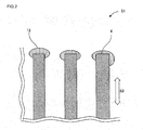
- a seal portion 12 As shown in Fig. 2 by applying glass paste on both the end faces of the substrate 51 and heating at predetermined temperature.
- glass seal or metal seal may be employed as the seal portion 12 of the support.
- glass seal is preferable in that it is excellent in matching the thermal expansion coefficient with a porous substrate.
- the glass has a thermal expansion coefficient close to that of the porous support.
- nonleaded glass which does not contain lead or the like is preferable.
- a glass paste is applied on a surface of the support 51.
- the portion where the glass paste is applied and it is preferable to apply the glass paste in a portion for inhibiting gas, liquid, fine particles, and the like from moving from the inside of the support 51 to the outside or from the outside to the inside of the support 51.
- the glass paste is applied on both the end faces 4, 4 of the support 51.
- the support and the seeding sol are put in a pressure resistant container. At this time, the support is disposed to be immersed in a seeding sol. Then, a pressure resistance container is heated, and zeolite seed crystals are generated on a surface of the support by hydrothermal synthesis.
- the pressure resistant container there is no particular limitation on the pressure resistant container, there can be used a stainless steel pressure resistant container with a fluorine resin inner cylinder, a nickel metal pressure resistant container, a fluorine resin pressure resistant container, or the like.
- the support is immersed in the seeding sol, it is preferable to immerse at least a portion where zeolite seeding crystals are allowed to precipitate in the seeding sol, or the entire support may be immersed in the seeding sol.
- the temperature upon the hydrothermal synthesis is 90 to 130°C, more preferably 100 to 120°C. When the temperature is lower than 90°C, the hydrothermal synthesis hardly proceeds. When the temperature is above 130°C, it is impossible to obtain fine particles of zeolite seed crystals.
- the support is a porous article obtained by sintering alumina particles
- the temperature of hydrothermal synthesis in the aforementioned range (90 to 130°C)
- the time for the hydrothermal synthesis is preferably 3 to 18 hours, more preferably 6 to 12 hours. When it is shorter than 3 hours, there is a case that the hydrothermal synthesis does not proceed sufficiently. When it is longer than 18 hours, the zeolite seed crystal becomes too large.
- examples of the method for heating include a method of heating the pressure resistant container put in a hot air drier and a method of heating the pressure resistant container with directly attaching a heater to the container.
- the particle diameter of the zeolite seed crystals obtained is preferably 1 ⁇ m or less, more preferably 0.5 ⁇ m or less, particularly preferably 0.01 to 0. 5 ⁇ m. When it is larger than 1 ⁇ m, there is a case that a dense zeolite membrane having few defects in a membrane-forming step and a uniform thickness cannot be formed.
- the particle diameter of the zeolite seed crystals is obtained by a scanning electron microscope (SEM) observation. When the particle diameter of 1 ⁇ m or less is referred, it means that the maximum particle size is 1 ⁇ m or less.
- the support is preferably subjected to boil washing by the use of water. This enables to inhibit superfluous zeolite from forming.
- the washing time is not particularly limited as long as the seeding sol is washed out, it is preferable to repeat washing for 0.5 to 3 hours one to five times. After the washing, it is preferable to dry it at 60 to 120°C for 4 to 48 hours.
- the zeolite seed crystal is preferably formed on the surfaces of the channels 52 of the support 51.
- the support 51 is immersed in the seeding sol, it is preferably immersed in the state that the outer peripheral surface is covered with a tape of fluorine resin or the like.
- the same materials as the silica sol, structure directing agent, and water contained in the aforementioned seeding sol are used as the raw materials, and more water than the case of the seeding sol is used to preferably use a material having lower concentration than the seeding sol.
- water/silica molar ratio 100 to 700
- a dense zeolite membrane having few defects and even thickness can be formed.
- water/silica molar ratio is smaller than 100, since a silica concentration becomes high, zeolite crystals precipitate in the membrane-forming sol to deposit on the surface of the zeolite membrane, a crack or the like may be easily caused upon the activation treatment such as firing.
- a water silica molar ratio is larger than 700, there is a case that it is difficult to make a zeolite membrane hard.
- to be dense means that no impregnation with Rhodamine B is caused after the membrane formation.
- the membrane-forming sol upon mixing the silica sol with the aqueous solution of structure directing agent, they are mixed in such a manner that the molar ratio of TPA to silica (TPA/silica molar ratio) is within the range of preferably 0.01 to 0.5, more preferably 0.02 to 0.3.
- TPA/silica ratio When the TPA/silica ratio is below 0.01, it is difficult to make the membrane dense.
- the ratio is above 0.5, the zeolite crystal may deposit on the surface of the membrane.
- the zeolite seed crystals having precipitated on the surface of the support are grown by hydrothermal synthesis to form a zeolite membrane of zeolite crystals grown in a membrane form.
- the support where the zeolite seed crystals have precipitated and the membrane-forming sol are put in a pressure resistant container.
- the support is disposed so that it is immersed in the membrane-forming sol.
- the pressure resistant container is heated to form a zeolite membrane on a surface of the support by hydrothermal synthesis.
- the zeolite membrane obtained by hydrothermal synthesis contains tetrapropylammonium, it is preferable that a heat treatment is performed after the hydrothermal synthesis.
- the pressure resistant container it is preferable to use the pressure resistant container used for the aforementioned formation of zeolite seed crystals.
- the support is immersed in the membrane-forming sol, it is preferable to immerse a portion where the zeolite membrane is formed in the membrane-forming sol, and the entire support is immersed in the membrane-forming sol.
- the temperature upon performing hydrothermal synthesis is preferably raised up to 100 to 200°C.
- the temperature upon performing hydrothermal synthesis is preferably 100 to 200°C, more preferably 120 to 180°C. Such a temperature range enables to obtain a dense zeolite membrane having a uniform thickness and few defects. In a method for producing a zeolite membrane-provided article of the present invention, it is possible to produce such a high-quality membrane with good repeatability, and the production efficiency is high. When the temperature is lower than 100°C, hydrothermal synthesis may hardly progress. When the temperature is above 200°C, it may be difficult to make the resultant zeolite membrane dense with uniform thickness and few defects.
- the synthesis time of the hydrothermal synthesis is preferably 3 to 120 hours, more preferably 6 to 90 hours, particularly preferably 10 to 72 hours.
- the time is shorter than 3 hours, there is a case that the hydrothermal synthesis does not proceed sufficiently.
- the time is longer than 120 hours, the zeolite membrane may become too thick with uneven thickness.
- to be dense means that no impregnation with Rhodamine B is caused after the membrane formation.
- SEM scanning electron microscope
- the zeolite membrane is formed on the surface of the support by hydrothermal synthesis, it is preferable to subject the support to boil washing. This enables to inhibit superfluous zeolite crystals to adhere to the zeolite membrane.
- the washing time is not particularly limited, it is preferable to repeat washing for 0.5 to 3 hours one to five times. After the washing, it is preferable to dry it at 60 to 120°C for 4 to 48 hours.
- a method for producing the zeolite separation membrane-provided article of the present embodiment has at least one membrane-growing step where the zeolite membrane formed on the surface of the support is further grown after the aforementioned "(2) Membrane-formation step".
- the support is monolith-shaped and that a zeolite membrane is formed on the surfaces of the channels
- the silica component contained in the membrane-forming sol is insufficient in the channels to make membrane formation insufficient only by " (2) membrane-forming step”.
- the membrane-growing step may be performed not only once, but also two or more times.
- membrane growing step are preferably the same as those of the "(II-2) membrane-forming step” except that the "support where a zeolite membrane is formed on the surface obtained in the (2) membrane-forming step” is used in place of using the "support where the zeolite seed crystals have precipitated on the surface thereof obtained in the (1) seed crystal-forming step".
- the heating temperature is preferably 400 to 1000°C, particularly preferably 500 to 800°C.
- the temperature rise speed is preferably 0.1°C/min. or more, more preferably 0.2°C/min. or more. There may be used a method where the temperature is raised in the aforementioned temperature range by putting a zeolite separation membrane-provided article in a heating appliance where the temperature is maintained in the aforementioned temperature range.
- the heating time is preferably 1 to 60 hours.
- the temperature fall speed is preferably 0.5°C/min. or more, particularly preferably 1°C/min. or more.
- a zeolite membrane 11 is disposed on the support 51, and there can be produced a separation membrane-provided article provided with a zeolite membrane 11 having an N 2 gas permeation speed at room temperature of 1.0 ⁇ 10 -6 mol ⁇ m -2 ⁇ s -1 ⁇ Pa -1 or more and a permeation speed ratio of 1,3,5-trimethylbenzene/N 2 at room temperature of 0.17 or more and being free from dyeing caused by the impregnation with Rhodamine B.
- a method for separating a mixed fluid of two or more different components using a zeolite separation membrane-provided article of the present invention there may be employed a method where gas permeation is caused with supplying the mixed fluid as a liquid (pervaporation method) or a method where gas permeation is caused by supplying the mixed fluid as steam.
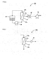
- the separation can be performed by the use of a mixed fluid separation device 101 as shown in Figs. 5 to 6 .
- the mixed fluid separation device 101 of the present invention includes a separation section for separating a raw material side space from a permeation side space by a porous substrate, a supply section for supplying a mixed fluid to the raw material side space, a permeation collection section for collecting permeation liquid and/or permeation gas having penetrated the mixed fluid separation membrane.
- the separation section is provided with the aforementioned zeolite membrane 11 for the mixed fluid and constituted of a SUS module 37 having a porous support 51 supporting the zeolite membrane 11.
- the supply section is constituted of a raw material tank 35 and a circulation pump 36
- the permeation collection section is constituted of a cooling trap 38 as a cooling apparatus and a vacuum pump 39.
- the raw material tank 35 heats the liquid mixture (raw material) put in a tank and maintains the mixture at a predetermined temperature (e.g., 50°C).
- a supply fluid introduction port 37a and the supply fluid discharge port 37b are formed in such a manner that they communicate with the raw material side space 31, and a permeation fluid collection port 37c for discharging the permeation steam outside is formed in the permeation side space 32.
- the liquid mixture in the raw material tank 35 is supplied to the raw material side space 31 of the SUS module 37 by the circulation pump 36.
- the SUS module 37 is constituted in such a manner that the monolith-shaped substrate (support) 51 having a zeolite membrane formed thereon can be disposed in a predetermined position by means of an O-ring 33 on the outer peripheral portions of both the ends.
- the SUS module 37 is separated into the raw material side space 31 and the permeation side space 32 by the glass seal (seal portion 12) and the zeolite membrane 11.
- the cooling trap 38, and the vacuum pump 39 are provided to collect permeation steam discharged from the permeation fluid collection port 37c by a liquid N 2 trap (cooling trap 38).
- the raw material is supplied to the raw material side space 31 of the SUS module 37 by the supply fluid introduction port 37a by a circulation pump 36, and the raw material discharged from the supply fluid discharge port 37b is returned to the raw material tank 35 to circulate the raw material.
- the aforementioned liquid mixture is used as the raw material.
- a gas mixture where a liquid mixture is evaporated by providing a carburetor between the raw material tank 35 and the SUS module 37. The mixture is brought into contact with a membrane supply side 11a of the zeolite membrane 11 as a supply mixture from the supply fluid introduction port 37a.
- the degree of vacuum of the permeation side space 32 is controlled to be a predetermined reduced pressure (e.g, about 0.5 Torr) by a pressure controller. This enables to separate a mixed fluid.
- gas separation can be performed by using, for example, a mixed fluid separation device 102 as shown in Figs. 5 and 7 .
- the mixed fluid separation device 102 of the present invention includes a separation section for separating a raw material side space from a permeation side space, a supply section for supplying a mixed fluid to the raw material side space, a permeation collection section for collecting permeation gas having penetrated the mixed fluid separation membrane from the permeation side space.
- the separation section is provided with the aforementioned zeolite membrane 11 for a mixed fluid and constituted of a SUS module 37 having a porous substrate 51 supporting the membrane 11.
- a supply fluid introduction port 37a and the supply fluid discharge port 37b are formed in such a manner that they communicate with the raw material side space 31, and a permeation fluid collection port 37c for discharging the permeation steam outside is formed in the permeation side space 32.
- the SUS module 37 is constituted in such a manner that the monolith-shaped substrate (support) 51 having a zeolite membrane formed thereon can be disposed in a predetermined position by means of an O-ring 33 on the outer peripheral portions of both the ends.
- the SUS module 37 is separated into the raw material side space 31 and the permeation side space 32 by the glass seal (seal portion 12) and the zeolite membrane 11.
- a gas mixture as a raw material where a predetermined pressure is applied by a pressure controller is supplied to the raw material side space 31 of the SUS module 37 by the supply fluid introduction port 37a.
- the mixture is brought into contact with a membrane supply side 11a of the zeolite membrane 11 as a supply mixture from the supply fluid introduction portion 37a.
- a specific component permeates toward the membrane permeation side 11b and is discharged from the permeation fluid collection port 37c, thereby separating the mixed fluid.
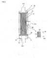
- the resultant seeding sol 13a was put in a 300 ml fluorine resin pressure resistant container 10 as shown in Fig. 3 , and a monolith-shaped porous alumina support 51 having a diameter of 30 mm, a length of 160 mm and having glass seals (seal portions 12) on both the end portions and having 37 straight holes each having a diameter of 3 mm was immersed in the sol after covering the outside with a fluorine resin tape to react in a hot air drier at 110°C for 12 hours.
- the support 51 was fixed to the pressure resistant container 10 by a fluorine resin receiving jig 15.
- the fluorine resin tape on the outside was removed, and the support 51 was subjected to boil washing five times, followed by drying at 80°C for 16 hours.
- the MFI type zeolite was confirmed by X-ray diffraction of the crystal particles after the reaction.
- the resultant membrane-forming sol 13b was put in a 300 ml fluorine resin pressure resistant container 10 as shown in Fig. 3 in the same manner as in the aforementioned "Formation of zeolite seed crystal", and the aforementioned porous alumina support 51 where the zeolite seed crystals had precipitated was immersed in the sol after covering the outside with a fluorine resin tape.
- the temperature was raised to 160°C for reaction in a hot air drier at 160°C for 24 hours, and then the temperature was decreased. After the reaction, the fluorine resin tape on the outside was removed, and the support 51 was subjected to boil washing five times, followed by drying at 80°C for 16 hours to obtain a zeolite separation membrane-provided article.
- the step for removing the structure directing agent from the zeolite separation membrane-provided article was performed with the temperature rise speed of 0.2°C/min., maintenance of the heating temperature of 600°C for 4 hours, and the temperature fall speed of 1°C/min.
- the MFI type zeolite was confirmed by X-ray diffraction of the device layers inside the channels after the reaction.
- a zeolite separation membrane-provided article was put in an electric furnace whose temperature was raised to 600°C and maintained before the zeolite separation membrane-provided article was put therein (The temperature rise speed was higher than 0.2°C/min.) and allowed to stand still. After 24 hours passed, it was taken out from the electric furnace (The temperature fall speed was higher than 1°C/min.).
- the zeolite separation membrane-provided article was obtained from the same steps as in Example 1 except for the above operations.
- the MFI type zeolite was confirmed by X-ray diffraction of the device layers inside the channels after the reaction.
- the step of removing the structure directing agent was performed with the temperature rise speed of 0.1°C/min., maintenance of the heating temperature of 600°C for 4 hours, and the temperature fall speed of 0.5°C/min.
- the MFI type zeolite was confirmed by X-ray diffraction of the dense layers inside the channels after the reaction.
- the production was performed according to the Non Patent Document 1 ( Separation Purification Technology, 25 (2001) 297-306 ) described in the background art. There were mixed 12.69g of 40 mass% tetrapropylammonium hydroxide solution (produced by SACHEM Chemical Company) and 6.62g of tetrapropylammonium bromide (produced by Wako Pure Chemical Industries, Ltd.), and 203.05 g of distilled water and 20g of approximately 30 mass% silica sol (trade name of Snowtex S produced by Nissan Chemical Industries, Ltd.) were further added. They were stirred with a magnetic stirrer at room temperature for 30 minutes to obtain a seeding sol.
- This seeding sol was put in a fluorine resin pressure resistant container, and a monolith-shaped porous alumina support having a diameter of 30 mm, a length of 160 mm and having glass seals on both the end portions and having 37 straight holes each having a diameter of 3 mm was immersed in the sol after covering the outside with a fluorine resin tape to react in a hot air drier at 180°C for 30 hours. After the reaction, the fluorine resin tape on the outside was removed, and the support was subjected to boil washing five times, followed by drying at 80°C for 16 hours to obtain a zeolite separation membrane-provided article.
- the step for removing the structure directing agent from the zeolite separation membrane-provided article was performed with the temperature rise speed of 0.1°C/min., maintenance of the heating temperature of 500°C for 4 hours, and the temperature fall speed of 0.1°C/min.
- the MFI type zeolite was confirmed by X-ray diffraction of the crystal particles after the reaction.
- Example 1 Each of the tetrapropylammonium hydroxide solution and the tetrapropylammonium bromide for the seeding sol was one tenth of Example 1, and each of the tetrapropylammonium hydroxide solution and the tetrapropylammonium bromide for the membrane-forming sol was one tenth of Example 1.
- the other conditions were the same as those of Example 1.
- the step of removing the structure directing agent was performed with the temperature rise speed of 0.01°C/min., maintenance of the heating temperature of 600°C for 4 hours, and the temperature fall speed of 0.05°C/min.
- the MFI type zeolite was confirmed by X-ray diffraction of the dense layers inside the pores after the reaction.
- Titanium isopropoxide was subjected to hydrolysis in the presence of nitric acid to obtain a titania sol.
- the titania sol was diluted with distilled water to obtain a sol solution, and it was sent in and brought into contact with the inside of substrate cells to form membranes in the cells. Then, the sample was dried and subj ected to a thermal treatment at 500°C.
- the pore volume and the pore distribution were measured with respect to the zeolite membrane in each of zeolite membrane-provided articles of Example 3 and Comparative Example 4.
- the target to be measured was pores having a pore diameter of 40 nm or less, the measurement was performed by a nitrogen adsorption method (-196°C) with a measurement apparatus of ASAP 2020 produced by Micromeritics Instrument Corporation.
- the Saito-Foley method was applied in the pore diameter range of 2 nm or less
- the Barrett-Joyner-Halenda method was applied in the pore diameter range of 2 to 40 nm.
- the entire pore volume was the sum of the volume of pores having pore diameters of 2 nm or less and the volume of pores having pore diameters in the range of 2 to 40 nm.
- Example 3 had a sharp peak in a pore diameter range of 0.76 nm or less and a broad peak in the vicinity of a pore diameter range of 0.76 to 2 nm.
- the entire pore volume of the pores having pore diameters up to 40 nm was 0.2 cc/g, the pore volume of the pores having pore diameters of 0.76 nm or less was 0.
- the pore volume of the pores having pore diameters of 0.76 to 2 nm was 0.04 cc/g
- the pore volume of the pores having pore diameters of 2 to 40 nm was 0.01 cc/g.
- the pore volume of pores having pore diameters of 0.76 to 2 nm was 0.04 cc/g in the narrow range of 1.24 nm
- the pore volume of the pores having pore diameters of 2 to 40 nm was 0.01 cc/g in the wide range of 38 nm. Therefore, it can be said that there is no pore having a pore diameter practically larger than 2 nm.
- the pore diameters of Comparative Example 4 were measured in the same manner as in Example 1 to find a peak in the pore diameter range of 1 nm or less and a broad peak in the pore diameter range of 2 to 4 nm.
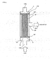
- FIG. 4 An apparatus shown in Fig. 4 was used to carry out a single component gas (N 2 ) permeation test.
- the SUS module 137 was separated into a gas supply side space 131 and a gas permeation side space 132 by an o-ring 133, a glass seal (seal portion 12), and a zeolite membrane.
- the gas supply side space 131 was closed in the latter part of the SUS module 137, the gas was supplied to the supply side space of the SUS module 137 from the supply gas introduction port 137a by an evaluation gas bomb connected on the supply side, and the gas discharged from the supply gas discharge port 137b accumulated to apply a predetermined pressure to a membrane.
- a gauge pressure of the gas supply side space 131 was 0.1 MPa, and the pressure in the gas permeation side space 132 was atmospheric pressure.
- the pervaporation was performed by the use of a mixture separation device 101 as shown in Figs. 5 to 6 .
- 1,3,5-trimethylbenzene put in a tank was heated and maintained at a predetermined temperature (about 50°C) by a raw material tank 35.
- a raw material was supplied to the raw material side space 31 of the SUS module 37 from the supply fluid introduction port 37a by a circulation pump 36, and the raw material discharged from the supply fluid discharge port 37b is returned to the raw material 35 to allow the raw material to circulate.
- the permeation steam permeating toward the membrane permeation side 11b of the separation membrane 11 and discharged from the permeation fluid collection port 37c was collected by a liquid N 2 trap.
- the degree of vacuum of the permeation side space 32 is controlled to be a predetermined reduced pressure (e.g, about 0.5 Torr) by a pressure controller. This enables to change the composition of the liquid mixture.
- the test was performed with 1,3,5-trimethylbenzene at 50°C with a degree of vacuum of 0.2 torr and a measurement time of 30 min.
- the mass of the liquid obtained was weighed with an electronic balance, and the component of liquid was analyzed by a gas chromatography.
- the permeation speed obtained as a result of the aforementioned pervaporation test is shown in Table 1.
- Rhodamine B An aqueous solution of 0.3 mass% Rhodamine B was produced and pored inside the membrane (through-holes), and presence/absence of dyeing on the outside substrate was confirmed by eye observation and an optical microscope. The results are shown in Table 1.
- the permeation speed of nitrogen (N 2 ) was 1.0 ⁇ 10 -6 mol ⁇ m -2 ⁇ s -1 ⁇ Pa -1 or more, and the permeation speed ratio of 1,3,5-trimethylbenzene/N 2 permeation speed ratio was 0.17 or more.
- the permeation speed of nitrogen was high, it was found out that the amount of through-pores capable of permeation was sufficient.
- each of Examples 1 to 3 was a zeolite separation membrane-provided article having pores inherent to the zeolite crystals and pores other than the pores inherent to the zeolite crystals in the range of 0.76 nm or more and about 2 nm or less.
- Example 2 since the order of 1,3,5-trimethylbenzene permeation speed from the highest is Example 2, Example 1, and Example 3, the order of the amount of pores other than the pores inherent to the zeolite crystals from the highest is Example 2, Example 1, and Example 3.
- Example 3 by the pore distribution measurement by a N 2 adsorption method of Example 3, it was confirmed that it had a sharp peak in the pore diameter range of 0.76 nm or less, a broad peak in the pore diameter range of 0.76 to 2 nm, and no peak in the pore diameter range of 2 nm or more.
- Comparative Example 1 since the temperature fall speed in the heat treatment where the structure directing agent was removed was so slow as 0.1°C/min., there was no pore other than the pores inherent to zeolite crystals, and 1,3,5-trimethylbenzene did not permeate. In Comparative Example 2, since a dense membrane could not be obtained because the amount of the structure directing agent is small, there was the dyeing by the impregnation with Rhodamine B. In Comparative Example 3, since the temperature rise speed in the heat treatment for removing the structure directing agent was so slow as 0.01°C/min., there are few pores other than the pores inherent to zeolite crystals, and the 1,3,5-trimethylbenzene/N 2 permeation speed ratio was not sufficient. In Comparative Example 4, since the pores were large, there was the dyeing by the impregnation with Rhodamine B.
- the criteria of the judgment were that the permeation flux of the permeable component was 150% or more with respect of that of Comparative Example 3 and that the increase and decrease of the separation coefficient was 50% or more with respect to Comparative Examples 3.
- the increase and decrease of the permeation flux was used in the propylene/argon mixed gas separation test.
- the separation coefficient means a value of the ratio of ethanol concentration (mass%) to water concentration (mass%) in the permeation liquid with respect to the ratio of ethanol concentration (mass%) to water concentration (mass%) in the supply liquid as shown in the formula shown below.
- the permeation flux means the mass of the entire substances passed through the separation membrane per unit time (hour) and unit area (m 2 ).
- Separation coefficient ethanol concentration in permeation liquid / water concentration in permeation liquid / ( ethanol concentration in supply liquid / water concentration in supply liquid
- the n-hexane/benzene pervaporation (PV) test was performed at 50°C with a permeation side degree of vacuum of 0.2 torr and a measurement time of 20 min. (between 20 and 40 minutes from the start) in the same manner as described above.
- the separation coefficient means a value of the ratio of n-hexane concentration (mass%) to benzene concentration (mass%) in the permeation liquid with respect to the ratio of n-hexane concentration (mass%) to benzene concentration (mass%) in the supply liquid as shown in the formula shown below.
- the n-heptane/toluene pervaporation (PV) test was performed at 50°C with a permeation side degree of vacuum of 0.2 torr and a measurement time of 180 min. (between 0 and 180 minutes from the start) in the same manner as described above.
- the separation coefficient means a value of the ratio of n-heptane concentration (mass%) to toluene concentration (mass%) in the permeation liquid with respect to the ratio of n-heptane concentration (mass%) to toluene concentration (mass%) in the supply liquid as shown in the formula shown below.
- the n-hexane/2,2-dimethylbutane pervaporation (PV) test was performed at 35°C with a permeation side degree of vacuum of 0.2 torr and a measurement time of 180 min. (between 0 and 180 minutes from the start) in the same manner as described above.
- the separation coefficient means a value of the ratio of n-hexane concentration (mass%) to 2,2-dimethylbutane concentration (mass%) in the permeation liquid with respect to the ratio of n-hexane concentration (mass%) to 2,2-dimethylbutane concentration (mass%) in the supply liquid as shown in the formula shown below.
- a mixed gas separation test was performed by the use of a mixture separation device 102 as shown in Figs. 5 and 7 .
- a raw material was supplied to the raw material space 31 of the SUS module 37 from the supply fluid introduction port 37a.
- the pressure difference between the membrane supply side and the membrane permeation side of the zeolite membrane 11 as a drive force, a specific component permeated toward the membrane permeation side 11b and was discharged from the permeation fluid collection port 37c, thereby separating the mixed fluid.
- the test was performed at 30°C with a supply side pressure of 0.7 MPa (absolute pressure) and a permeation side pressure of 0.1 MPa (absolute pressure).
- the permeation gas flow rate was measured by a dry gas meter or a soap membrane flowmeter provided on the gas collection port 137c side to evaluate the permeation speed (nmol ⁇ m -2 ⁇ s -1 ⁇ Pa -1 ).
- the composition of permeation gas was analyzed by a gas chromatography. The permeation speed obtained as a result of the aforementioned mixed gas separation test is shown in Table 6.
- the separation coefficient means a value of the ratio of propylene concentration (mass%) to argon concentration (mass%) in the permeation liquid with respect to the ratio of propylene concentration (mass%) to argon concentration (mass%) in the supply liquid as shown in the formula shown below.
- Separation coefficient propylene concentration in permeation gas / argon concentration in permeation gas / propylene concentration in supply gas ) / argon concentration in supply gas
- the permeation speed of nitrogen (N 2 ) was 1.0 ⁇ 10 -6 mol ⁇ m -2 ⁇ s -1 ⁇ Pa -1 or more, the permeation speed ratio of 1,3,5-trimethylbenzene/N 2 permeation speed ratio was 0.17 or more, and there was no dyeing by the impregnation with Rhodamine B. Therefore, it was confirmed that the articles had pores larger than the pores inherent to the zeolite crystals in the range of 0.76 nm to about 2 nm in addition to the pores inherent to the zeolite crystals.
- Example 2 since the order of permeation speed of 1,3,5-trimethylbenzene from the highest was Example 2, Example 1, and Example 3, it can be said that the amount of pores other than the pores inherent to the zeolite crystals from the highest was Example 2, Example 1, and Example 3. In addition, it was confirmed that there is practically no pores in the range of about 2 nm or more.
- a zeolite membrane-provided article can achieve both high permeability and high separability in the separation of ethanol/water, n-hexane/benzene, n-heptane/toluene, n-hexane/2,2-dimethylbutane, and propylene/argon. This seems to be because the pores inherent to the zeolite crystals are in the range of 0.76 nm or less and because gaps or pores larger than the pores inherent to the zeolite crystals are in the range of 0.76 nm to about 2 nm, where both high permeability and high separability can be achieved in these separation systems.
- a zeolite separation membrane-provided article of the present invention has gaps or pores larger than pores of the zeolite crystals and controlled to be within an appropriate range of 0.76 nm or more and about 2 nm or less, both high permeability and high separability can be achieved in the case of performing separation of linear chain hydrocarbon from side chain hydrocarbon, linear chain hydrocarbon from aromatic hydrocarbon, alcohol from water, linear chain saturated hydrocarbon from inorganic gas.
Landscapes
- Chemical & Material Sciences (AREA)
- Chemical Kinetics & Catalysis (AREA)
- Engineering & Computer Science (AREA)
- Inorganic Chemistry (AREA)
- Crystallography & Structural Chemistry (AREA)
- Oil, Petroleum & Natural Gas (AREA)
- General Chemical & Material Sciences (AREA)
- Analytical Chemistry (AREA)
- Manufacturing & Machinery (AREA)
- Life Sciences & Earth Sciences (AREA)
- Geology (AREA)
- Separation Using Semi-Permeable Membranes (AREA)
- Silicates, Zeolites, And Molecular Sieves (AREA)
Applications Claiming Priority (3)
| Application Number | Priority Date | Filing Date | Title |
|---|---|---|---|
| JP2009062770 | 2009-03-16 | ||
| JP2009187972 | 2009-08-14 | ||
| PCT/JP2010/052683 WO2010106881A1 (fr) | 2009-03-16 | 2010-02-23 | Structure dotée d'une membrane de séparation zéolitique, procédé de production associé, procédé de séparation de fluides mixtes et dispositif de séparation de fluides mixtes |
Publications (2)
| Publication Number | Publication Date |
|---|---|
| EP2409758A1 true EP2409758A1 (fr) | 2012-01-25 |
| EP2409758A4 EP2409758A4 (fr) | 2013-07-31 |
Family
ID=42739546
Family Applications (1)
| Application Number | Title | Priority Date | Filing Date |
|---|---|---|---|
| EP10753376.2A Ceased EP2409758A4 (fr) | 2009-03-16 | 2010-02-23 | Structure dotée d'une membrane de séparation zéolitique, procédé de production associé, procédé de séparation de fluides mixtes et dispositif de séparation de fluides mixtes |
Country Status (5)
| Country | Link |
|---|---|
| US (1) | US8361197B2 (fr) |
| EP (1) | EP2409758A4 (fr) |
| JP (1) | JPWO2010106881A1 (fr) |
| CN (1) | CN102348494B (fr) |
| WO (1) | WO2010106881A1 (fr) |
Cited By (2)
| Publication number | Priority date | Publication date | Assignee | Title |
|---|---|---|---|---|
| EP2832694A4 (fr) * | 2012-03-30 | 2016-04-06 | Ngk Insulators Ltd | Cristal germe de zéolite ddr, procédé pour le produire, et procédé pour produire un film de zéolite ddr |
| KR101970761B1 (ko) * | 2018-12-05 | 2019-04-22 | 부경대학교 산학협력단 | 추출증류를 이용한 1,2,4-트리메틸벤젠 분리장치 및 이 장치를 이용한 분리방법 |
Families Citing this family (26)
| Publication number | Priority date | Publication date | Assignee | Title |
|---|---|---|---|---|
| JP2009262098A (ja) * | 2008-04-28 | 2009-11-12 | Ne Chemcat Corp | 選択還元触媒を用いた排気ガス浄化方法 |
| US9079162B2 (en) * | 2008-04-28 | 2015-07-14 | BASF SE Ludwigshafen | Fe-BEA/Fe-MFI mixed zeolite catalyst and process for the treatment of NOX in gas streams |
| EP2726727B1 (fr) * | 2011-06-30 | 2016-03-02 | Corning Incorporated | Dispositif échangeable de séparation de combustible |
| WO2014069676A1 (fr) * | 2012-11-01 | 2014-05-08 | 日本碍子株式会社 | Structure céramique à membrane de séparation et son procédé de réparation |
| US10584906B2 (en) | 2013-08-09 | 2020-03-10 | Carrier Corporation | Refrigeration purge system |
| WO2015020719A1 (fr) | 2013-08-09 | 2015-02-12 | Carrier Corporation | Système de purge pour système refroidisseur |
| JP6252249B2 (ja) * | 2014-02-28 | 2017-12-27 | 日本ゼオン株式会社 | 膜分離方法 |
| US10039999B2 (en) | 2014-07-22 | 2018-08-07 | Joern Ilja Siepmann | Zeolites for separation of ethanol and water |
| JP6211481B2 (ja) * | 2014-08-01 | 2017-10-11 | Jxtgエネルギー株式会社 | ノルマルパラフィンまたはパラキシレンの分離方法およびゼオライト膜複合体 |
| JP6270685B2 (ja) * | 2014-10-08 | 2018-01-31 | 学校法人早稲田大学 | ノルマルパラフィンの分離方法 |
| WO2016093192A1 (fr) * | 2014-12-09 | 2016-06-16 | 日本碍子株式会社 | Structure de membrane de séparation et son procédé de fabrication |
| US20190247783A1 (en) * | 2016-03-31 | 2019-08-15 | Zeon Corporation | Membrane separation method and membrane separation device |
| JP6757606B2 (ja) * | 2016-06-21 | 2020-09-23 | 日立造船株式会社 | Mfi型ゼオライト(シリカライト)を用いた分離膜の製造方法 |
| JP7111094B2 (ja) * | 2017-03-28 | 2022-08-02 | 日本ゼオン株式会社 | 分離膜及び分離膜の製造方法 |
| JP6861273B2 (ja) * | 2017-03-31 | 2021-04-21 | 日本碍子株式会社 | ゼオライト膜複合体、および、ゼオライト膜複合体の製造方法 |
| WO2019187640A1 (fr) * | 2018-03-30 | 2019-10-03 | 日本碍子株式会社 | Corps composite de membrane en zéolite, procédé de production de corps composite de membrane en zéolite, et procédé de séparation |
| KR102034765B1 (ko) | 2018-04-20 | 2019-10-22 | 고려대학교 산학협력단 | 염색 분자를 이용한 제올라이트 분리막의 후처리 방법 |
| WO2020050137A1 (fr) * | 2018-09-05 | 2020-03-12 | 日本ゼオン株式会社 | Procédé de production de pipérylène |
| CN112334721A (zh) | 2018-12-03 | 2021-02-05 | 开利公司 | 增强制冷吹扫系统 |
| CN112334720A (zh) | 2018-12-03 | 2021-02-05 | 开利公司 | 增强的制冷净化系统 |
| US11686515B2 (en) | 2018-12-03 | 2023-06-27 | Carrier Corporation | Membrane purge system |
| EP3891448A1 (fr) | 2018-12-03 | 2021-10-13 | Carrier Corporation | Système de purge de réfrigération amélioré |
| BR112022022775A2 (pt) * | 2020-05-25 | 2022-12-13 | Ngk Insulators Ltd | Complexo de membrana de separação, método de produção do complexo de membrana de separação e método de separação |
| KR20230101813A (ko) * | 2020-11-02 | 2023-07-06 | 미쯔비시 케미컬 주식회사 | 제올라이트, 제올라이트의 제조 방법, 조성물, 액상 조성물, 액상 봉지제, 수지 복합재, 봉지재, 봉지재의 제조 방법, 및 디바이스 |
| DE112022002077T5 (de) * | 2021-06-03 | 2024-01-18 | Ngk Insulators, Ltd. | Mischgastrennverfahren und Mischgastrenneinrichtung |
| CN113599977B (zh) * | 2021-07-23 | 2022-06-17 | 南京工业大学 | 一种采用中空纤维dd3r分子筛膜提纯氦气的方法 |
Family Cites Families (14)
| Publication number | Priority date | Publication date | Assignee | Title |
|---|---|---|---|---|
| GB9413863D0 (en) * | 1994-07-08 | 1994-08-24 | Exxon Chemical Patents Inc | Molecular sieves and processes for their manufacture |
| JP2981884B1 (ja) * | 1998-06-29 | 1999-11-22 | 工業技術院長 | ゼオライト膜の製造方法 |
| GB9905561D0 (en) * | 1999-03-11 | 1999-05-05 | Exxon Chemical Patents Inc | Molecular sieve layers and process for their manufacture |
| FR2820342B1 (fr) * | 2001-02-07 | 2003-12-05 | Inst Francais Du Petrole | Procede de preparation de membranes zeolithiques supportees par cristallisation controlee en temperature |
| JP2002348579A (ja) | 2001-05-23 | 2002-12-04 | Nard Inst Ltd | ゼオライト系分離膜を用いた炭化水素混合物の分離方法、および分離して炭化水素を得る方法 |
| JP4494685B2 (ja) | 2001-09-17 | 2010-06-30 | 日本碍子株式会社 | ゼオライト積層複合体及びその製造方法 |
| US7476635B2 (en) * | 2002-06-03 | 2009-01-13 | Institut Francais Du Petrole | Process for making supported thin zeolite membrane |
| DE102004001974A1 (de) * | 2004-01-13 | 2005-08-04 | Basf Ag | Komposit-Membran |
| CA2601258A1 (fr) * | 2005-03-11 | 2006-09-21 | Uop Llc | Membranes de criblage microporeuses a grand flux, separateurs contenant ces membranes et procedes mettant en oeuvre de telles membranes |
| JP5108525B2 (ja) * | 2005-11-17 | 2012-12-26 | 日本碍子株式会社 | ゼオライト膜の製造方法 |
| WO2007058388A1 (fr) | 2005-11-17 | 2007-05-24 | Ngk Insulators, Ltd. | Structure comportant une pellicule de zéolite orientée |
| US8196755B2 (en) * | 2006-06-13 | 2012-06-12 | Basf Se | Process for producing a composite membrane |
| US8043418B2 (en) * | 2006-12-08 | 2011-10-25 | General Electric Company | Gas separator apparatus |
| JP2008188564A (ja) | 2007-02-07 | 2008-08-21 | National Institute Of Advanced Industrial & Technology | 有機混合溶液の分離膜及びその製造方法 |
-
2010
- 2010-02-23 EP EP10753376.2A patent/EP2409758A4/fr not_active Ceased
- 2010-02-23 CN CN201080012623.0A patent/CN102348494B/zh not_active Expired - Fee Related
- 2010-02-23 JP JP2011504792A patent/JPWO2010106881A1/ja active Pending
- 2010-02-23 WO PCT/JP2010/052683 patent/WO2010106881A1/fr not_active Ceased
-
2011
- 2011-09-13 US US13/231,440 patent/US8361197B2/en not_active Expired - Fee Related
Cited By (3)
| Publication number | Priority date | Publication date | Assignee | Title |
|---|---|---|---|---|
| EP2832694A4 (fr) * | 2012-03-30 | 2016-04-06 | Ngk Insulators Ltd | Cristal germe de zéolite ddr, procédé pour le produire, et procédé pour produire un film de zéolite ddr |
| US9901882B2 (en) | 2012-03-30 | 2018-02-27 | Ngk Insulators, Ltd. | DDR zeolite seed crystal, method for producing same, and method for producing DDR zeolite membrane |
| KR101970761B1 (ko) * | 2018-12-05 | 2019-04-22 | 부경대학교 산학협력단 | 추출증류를 이용한 1,2,4-트리메틸벤젠 분리장치 및 이 장치를 이용한 분리방법 |
Also Published As
| Publication number | Publication date |
|---|---|
| US8361197B2 (en) | 2013-01-29 |
| US20120000358A1 (en) | 2012-01-05 |
| WO2010106881A1 (fr) | 2010-09-23 |
| CN102348494A (zh) | 2012-02-08 |
| CN102348494B (zh) | 2014-09-17 |
| JPWO2010106881A1 (ja) | 2012-09-20 |
| EP2409758A4 (fr) | 2013-07-31 |
Similar Documents
| Publication | Publication Date | Title |
|---|---|---|
| EP2409758A1 (fr) | Structure dotée d'une membrane de séparation zéolitique, procédé de production associé, procédé de séparation de fluides mixtes et dispositif de séparation de fluides mixtes | |
| Wegner et al. | Polycrystalline MFI zeolite membranes: xylene pervaporation and its implication on membrane microstructure | |
| Algieri et al. | Permeation properties of a thin silicalite-1 (MFI) membrane | |
| Agrawal et al. | Oriented MFI membranes by gel-less secondary growth of sub-100 nm MFI-nanosheet seed layers | |
| Matsufuji et al. | Separation of butane and xylene isomers with MFI-type zeolitic membrane synthesized by a vapor-phase transport method | |
| Chiang et al. | Membranes and films of zeolite and zeolite-like materials | |
| EP3225297B1 (fr) | Utilisation d'un ensemble support poreux-membrane zéolithique cha pour la séparation d'un mélange gazeux | |
| Hedlund et al. | High-flux MFI membranes | |
| Hedlund et al. | A masking technique for high quality MFI membranes | |
| Sato et al. | A high reproducible fabrication method for industrial production of high flux NaA zeolite membrane | |
| Aguado et al. | Continuous synthesis of NaA zeolite membranes | |
| Noack et al. | Influence of the Si/Al-ratio on the permeation properties of MFI-membranes | |
| Tanco et al. | Composite-alumina-carbon molecular sieve membranes prepared from novolac resin and boehmite. Part II: Effect of the carbonization temperature on the gas permeation properties | |
| US20090007780A1 (en) | Method of dehydration, dehydrating apparatus, and membrane reactor | |
| Aydani et al. | Silica sol gel assisted defect patching of SSZ-13 zeolite membranes for CO2/CH4 separation | |
| Wang et al. | Rapid synthesis of faujasite/polyethersulfone composite membrane and application for CO2/N2 separation | |
| WO2014069676A1 (fr) | Structure céramique à membrane de séparation et son procédé de réparation | |
| Yu et al. | A novel method for fabrication of high-flux zeolite membranes on supports with arbitrary geometry | |
| Zhang et al. | Thin porous metal sheet-supported NaA zeolite membrane for water/ethanol separation | |
| Ma et al. | Improved silicalite-1 membranes on 61-channel monolithic supports for n-butane/i-butane separation | |
| JPWO2010070992A1 (ja) | 液体混合物の分離方法、及び液体混合物分離装置 | |
| Ernst | Advances in nanoporous materials | |
| EA021262B1 (ru) | Способ получения молекулярно-ситовой мембраны для разделения газов | |
| WO2017150737A1 (fr) | Procédé de séparation de dioxyde de carbone et appareil de séparation de dioxyde de carbone | |
| Zah et al. | Single gas permeation through compositionally different zeolite NaA membranes: observations on the intercrystalline porosity in an unconventional, semicrystalline layer |
Legal Events
| Date | Code | Title | Description |
|---|---|---|---|
| PUAI | Public reference made under article 153(3) epc to a published international application that has entered the european phase |
Free format text: ORIGINAL CODE: 0009012 |
|
| 17P | Request for examination filed |
Effective date: 20110916 |
|
| AK | Designated contracting states |
Kind code of ref document: A1 Designated state(s): AT BE BG CH CY CZ DE DK EE ES FI FR GB GR HR HU IE IS IT LI LT LU LV MC MK MT NL NO PL PT RO SE SI SK SM TR |
|
| DAX | Request for extension of the european patent (deleted) | ||
| A4 | Supplementary search report drawn up and despatched |
Effective date: 20130703 |
|
| RIC1 | Information provided on ipc code assigned before grant |
Ipc: B01D 71/02 20060101AFI20130627BHEP Ipc: B01D 69/10 20060101ALI20130627BHEP Ipc: C01B 37/02 20060101ALI20130627BHEP |
|
| 17Q | First examination report despatched |
Effective date: 20170403 |
|
| REG | Reference to a national code |
Ref country code: DE Ref legal event code: R003 |
|
| STAA | Information on the status of an ep patent application or granted ep patent |
Free format text: STATUS: THE APPLICATION HAS BEEN REFUSED |
|
| 18R | Application refused |
Effective date: 20200704 |