EP2409856B1 - A wheel hub unit for vehicle wheels - Google Patents
A wheel hub unit for vehicle wheels Download PDFInfo
- Publication number
- EP2409856B1 EP2409856B1 EP11163934.0A EP11163934A EP2409856B1 EP 2409856 B1 EP2409856 B1 EP 2409856B1 EP 11163934 A EP11163934 A EP 11163934A EP 2409856 B1 EP2409856 B1 EP 2409856B1
- Authority
- EP
- European Patent Office
- Prior art keywords
- flinger
- cylindrical
- shoulder
- keying
- wheel hub
- Prior art date
- Legal status (The legal status is an assumption and is not a legal conclusion. Google has not performed a legal analysis and makes no representation as to the accuracy of the status listed.)
- Active
Links
Images
Classifications
-
- F—MECHANICAL ENGINEERING; LIGHTING; HEATING; WEAPONS; BLASTING
- F16—ENGINEERING ELEMENTS AND UNITS; GENERAL MEASURES FOR PRODUCING AND MAINTAINING EFFECTIVE FUNCTIONING OF MACHINES OR INSTALLATIONS; THERMAL INSULATION IN GENERAL
- F16C—SHAFTS; FLEXIBLE SHAFTS; ELEMENTS OR CRANKSHAFT MECHANISMS; ROTARY BODIES OTHER THAN GEARING ELEMENTS; BEARINGS
- F16C33/00—Parts of bearings; Special methods for making bearings or parts thereof
- F16C33/72—Sealings
- F16C33/76—Sealings of ball or roller bearings
- F16C33/78—Sealings of ball or roller bearings with a diaphragm, disc, or ring, with or without resilient members
- F16C33/7869—Sealings of ball or roller bearings with a diaphragm, disc, or ring, with or without resilient members mounted with a cylindrical portion to the inner surface of the outer race and having a radial portion extending inward
- F16C33/7879—Sealings of ball or roller bearings with a diaphragm, disc, or ring, with or without resilient members mounted with a cylindrical portion to the inner surface of the outer race and having a radial portion extending inward with a further sealing ring
-
- B—PERFORMING OPERATIONS; TRANSPORTING
- B60—VEHICLES IN GENERAL
- B60B—VEHICLE WHEELS; CASTORS; AXLES FOR WHEELS OR CASTORS; INCREASING WHEEL ADHESION
- B60B27/00—Hubs
- B60B27/0005—Hubs with ball bearings
-
- F—MECHANICAL ENGINEERING; LIGHTING; HEATING; WEAPONS; BLASTING
- F16—ENGINEERING ELEMENTS AND UNITS; GENERAL MEASURES FOR PRODUCING AND MAINTAINING EFFECTIVE FUNCTIONING OF MACHINES OR INSTALLATIONS; THERMAL INSULATION IN GENERAL
- F16J—PISTONS; CYLINDERS; SEALINGS
- F16J15/00—Sealings
- F16J15/16—Sealings between relatively-moving surfaces
- F16J15/32—Sealings between relatively-moving surfaces with elastic sealings, e.g. O-rings
- F16J15/3248—Sealings between relatively-moving surfaces with elastic sealings, e.g. O-rings provided with casings or supports
- F16J15/3252—Sealings between relatively-moving surfaces with elastic sealings, e.g. O-rings provided with casings or supports with rigid casings or supports
- F16J15/3256—Sealings between relatively-moving surfaces with elastic sealings, e.g. O-rings provided with casings or supports with rigid casings or supports comprising two casing or support elements, one attached to each surface, e.g. cartridge or cassette seals
- F16J15/3264—Sealings between relatively-moving surfaces with elastic sealings, e.g. O-rings provided with casings or supports with rigid casings or supports comprising two casing or support elements, one attached to each surface, e.g. cartridge or cassette seals the elements being separable from each other
-
- F—MECHANICAL ENGINEERING; LIGHTING; HEATING; WEAPONS; BLASTING
- F16—ENGINEERING ELEMENTS AND UNITS; GENERAL MEASURES FOR PRODUCING AND MAINTAINING EFFECTIVE FUNCTIONING OF MACHINES OR INSTALLATIONS; THERMAL INSULATION IN GENERAL
- F16C—SHAFTS; FLEXIBLE SHAFTS; ELEMENTS OR CRANKSHAFT MECHANISMS; ROTARY BODIES OTHER THAN GEARING ELEMENTS; BEARINGS
- F16C19/00—Bearings with rolling contact, for exclusively rotary movement
- F16C19/02—Bearings with rolling contact, for exclusively rotary movement with bearing balls essentially of the same size in one or more circular rows
- F16C19/14—Bearings with rolling contact, for exclusively rotary movement with bearing balls essentially of the same size in one or more circular rows for both radial and axial load
- F16C19/18—Bearings with rolling contact, for exclusively rotary movement with bearing balls essentially of the same size in one or more circular rows for both radial and axial load with two or more rows of balls
- F16C19/181—Bearings with rolling contact, for exclusively rotary movement with bearing balls essentially of the same size in one or more circular rows for both radial and axial load with two or more rows of balls with angular contact
- F16C19/183—Bearings with rolling contact, for exclusively rotary movement with bearing balls essentially of the same size in one or more circular rows for both radial and axial load with two or more rows of balls with angular contact with two rows at opposite angles
- F16C19/184—Bearings with rolling contact, for exclusively rotary movement with bearing balls essentially of the same size in one or more circular rows for both radial and axial load with two or more rows of balls with angular contact with two rows at opposite angles in O-arrangement
- F16C19/186—Bearings with rolling contact, for exclusively rotary movement with bearing balls essentially of the same size in one or more circular rows for both radial and axial load with two or more rows of balls with angular contact with two rows at opposite angles in O-arrangement with three raceways provided integrally on parts other than race rings, e.g. third generation hubs
-
- F—MECHANICAL ENGINEERING; LIGHTING; HEATING; WEAPONS; BLASTING
- F16—ENGINEERING ELEMENTS AND UNITS; GENERAL MEASURES FOR PRODUCING AND MAINTAINING EFFECTIVE FUNCTIONING OF MACHINES OR INSTALLATIONS; THERMAL INSULATION IN GENERAL
- F16C—SHAFTS; FLEXIBLE SHAFTS; ELEMENTS OR CRANKSHAFT MECHANISMS; ROTARY BODIES OTHER THAN GEARING ELEMENTS; BEARINGS
- F16C2326/00—Articles relating to transporting
- F16C2326/01—Parts of vehicles in general
- F16C2326/02—Wheel hubs or castors
Definitions
- the present invention relates to a wheel hub unit for vehicle wheels.
- Wheel hub units for vehicle wheels of the known type comprise an outer ring, a flanged inner ring for supporting the wheel, two annular arrangements of rolling-contact bodies situated between the two rings, and a sealing device positioned on the wheel side and comprising, in turn, a supporting shield mounted inside the outer ring, one or more sealing rings fixed to the supporting shield and a further shield, commonly called a "flinger", keyed on the inner ring and positioned in contact with the sealing lips.
- the flanged inner ring is provided with a small rolling ring for the annular arrangement on the opposite side to the wheel side and with a shoulder against which the small ring is positioned in axial abutment.
- the sealing quality of the sealing device described above is influenced in particular by the correct axial positioning of the flinger during assembly.
- the flinger is fitted on a cylindrical surface of the inner ring using the shoulder of the small ring as an axial reference point.
- this position does not always correspond to the desired position.
- the flinger is free to flex it could undergo deformation of the respective radial part arranged in contact with the said sealing lips. If one - or in the worst of cases - both the abovementioned events should occur, the sealing quality of the sealing device would be subject to deterioration such as to adversely affect even the correct operation of the wheel hub.
- the object of the present invention is to provide a wheel hub preamble of claim 1.
- Other wheel hub units are disclosed in DE 101 25 253 A1 and EP 1 277 978 A1 .
- the object of the present invention is to provide a wheel hub unit for vehicle wheels, which is able to overcome the drawbacks described above in a simple and low-cost manner.
- numeral 1 designates in its entirety a wheel hub unit for vehicle wheels.
- the unit 1 has an axis of rotation A and comprises a rolling bearing 1' in turn comprising an outer ring 2 and an inner ring 3 positioned coaxially and inside the outer ring 2.
- the unit 1 also comprises a flange 4 which is designed to support a wheel (not shown) and is transverse with respect to the axis A, fixed to the inner ring 3 and is made of the same material as the inner ring 3.
- the bearing 1' also comprises a plurality of rolling-contact bodies 5 arranged between the inner ring 3 and the outer ring 2 so as to allow relative rotation of the inner ring 3 and the outer ring 2.
- the outer ring 2 comprises a cylindrical edge 21 which faces the flange 4 and is delimited:
- the outer ring 2 also comprises a raceway 24 which is engaged by the rolling-contact bodies 5 and is axially delimited by a relief groove 25 adjacent to the surface 23.
- the inner ring 3 comprises a respective raceway 34, facing the raceway 24 and engaged by the rolling-contact bodies 5, and a cylindrical keying surface 31, which is adjacent to the raceway 34 and has a diameter greater than the maximum diameter of the raceway 34.
- the inner ring 3 also comprises a shoulder 32 which is axially delimited:
- the surface 31 and the surface 33 have the same degree of surface finish and are connected together by a radiused connecting portion 36, while the surface 33 and the surface 35 form between them an angular edge or corner 37 which is directed substantially towards the surface 23.
- the latter surface, i.e. surface 23, is parallel and axially aligned with almost all of the surface 31 and, being radially spaced from the surface 31, forms together with the surface 31 a seat 6.
- the seat 6 is delimited radially towards the outside by the surface 23 and radially towards the inside by the surface 31, while it is axially delimited by the surface 33, and is open towards the rolling-contact bodies 5.
- the cylindrical edge 21 and the surface 23 extend axially beyond the surface 31 towards the flange 4.
- the surface 23 is superimposed axially, but not radially, on the surface 35, with which it forms a passage 7 which communicates with the seat 6 and has radial dimensions smaller than the dimensions of the seat 6.
- the surface 35 is instead radially delimited towards the axis A by the angular edge 37 and is radially delimited on the opposite side of the angular edge 37 by another angular edge 38 which is formed by the surface 35 and by the flange 4 and subtends an angle wider than the angle subtended by the angular edge 37.
- the unit 1 further comprises a sealing device 8.
- This device is positioned on the so-called “wheel side” and inside the seat 6 so as to prevent the impurities from entering into the bearing 1'.
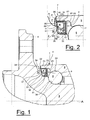
- the sealing device 8 comprises a supporting shield 81 which is mounted inside the outer ring 2, one or more sealing lips 82 fixed to the supporting shield 81 and a flinger 83 which is mounted, i.e. keyed, onto the surface 31 of the inner ring 3.
- the flinger 83 is positioned both in contact with the sealing lips 82 and next to the shoulder 32.
- the function of shoulder 32 is to provide an axial and well-defined abutment for the position of the flinger 83.
- the supporting shield 81 comprises a cylindrical portion 84 mounted on the surface 23 and a flanged portion 85 which is fixed to and transverse with respect to the cylindrical portion 84 and directly supports the lips 82.
- the shield 81 comprises a stopping edge 86 which is joined to the portion 84 on the opposite side to the flanged portion 85.
- the stopping edge 86 is directed radially outwards with respect to the portion 84 and is arranged in axial abutment against the surface 22 so as to define specifically the position of the shield 81 along the axis A, i.e. inside the seat 6.
- the flinger 83 comprises a respective cylindrical portion 87 which is mounted, e.g. keyed, onto the surface 31 and a flanged portion 88 which is fixed to and transverse with respect to the cylindrical portion 87 and is positioned in axial abutment against the surface 33 of the shoulder 32.
- the flinger 83 also comprises a portion 89 connecting together the portion 87 and the flanged portion 88 and an anti-vortex element 90 which is positioned at a free end of the flanged portion 88 and faces the passage 7, defining a labyrinth 91 with the portion 84 of the shield 81.
- the connecting portion 89 is in the form of an slanting plane, as in the example of embodiment shown in Figure 2 , or may have a curved shape or also may have a partially curved and partially flat shape.
- the radial length of the flanged portion 88 will also depend on the shape of the connecting portion 89 and in any case will always be such as to allow the anti-vortex element 90 to project beyond the angular edge 37 of the shoulder 32. In particular, comparing the radial length of the flanged portion 88 of the flinger 83 with a radial height of the shoulder 32, the radial length of the flanged portion 88 must not be more than one and a half times the radial height of the shoulder 32.
- the advantage of the shoulder 32 compared to the embodiments of the wheel hub units similar to the unit 1, but without the shoulder 32, as described in the introduction, consists not only in the precise and definitive definition of the axial position of the flinger 83, with an undoubted increase in reliability of the sealing device 8, but also in a simpler design of the flinger 83, which may have a smaller flange thickness with an undoubted saving in terms of material used without adversely affecting in any way the robustness either of the entire sealing device 8 or of the unit 1.
- the presence of the shoulder 32 will allow even more precise and reliable machining of the inner ring 3 since this inner ring 3 may be gripped on an axial level closer to the flange 4.
- the ratio between the radial height of the shoulder 32 and the radial length of the flanged portion 88 of the flinger 83 will ensure in any case that the flinger 83 is not in any way deformed during contact thereof against the shoulder 32.
- the presence of the latter will reduce substantially the risks of through-hardening in particular in the case of small-size units 1.
- at least all of the zone of the bearing 1' defined by the surfaces 35, 33, 31 and 34 is normally subject to a hardening treatment in order to provide the same surfaces with hardness and wear-resistance characteristics which are typical of bearings.
- the shoulder 32 increases the thickness of the inner ring 3 precisely at those points where most frequently through-hardening may occur.
Landscapes
- Engineering & Computer Science (AREA)
- General Engineering & Computer Science (AREA)
- Mechanical Engineering (AREA)
- Rolling Contact Bearings (AREA)
- Sealing Using Fluids, Sealing Without Contact, And Removal Of Oil (AREA)
Applications Claiming Priority (2)
| Application Number | Priority Date | Filing Date | Title |
|---|---|---|---|
| ITTO2009A000850A IT1397017B1 (it) | 2009-11-05 | 2009-11-05 | Gruppo mozzo ruota per ruote di veicoli |
| EP10190090 | 2010-11-05 |
Related Parent Applications (2)
| Application Number | Title | Priority Date | Filing Date |
|---|---|---|---|
| EP10190090 Division | 2009-11-05 | 2010-11-05 | |
| EP10190090.0 Division | 2010-11-05 |
Publications (2)
| Publication Number | Publication Date |
|---|---|
| EP2409856A1 EP2409856A1 (en) | 2012-01-25 |
| EP2409856B1 true EP2409856B1 (en) | 2015-07-29 |
Family
ID=41818407
Family Applications (1)
| Application Number | Title | Priority Date | Filing Date |
|---|---|---|---|
| EP11163934.0A Active EP2409856B1 (en) | 2009-11-05 | 2010-11-05 | A wheel hub unit for vehicle wheels |
Country Status (2)
| Country | Link |
|---|---|
| EP (1) | EP2409856B1 (it) |
| IT (1) | IT1397017B1 (it) |
Families Citing this family (2)
| Publication number | Priority date | Publication date | Assignee | Title |
|---|---|---|---|---|
| DE102017128969A1 (de) * | 2017-12-06 | 2019-06-06 | Schaeffler Technologies AG & Co. KG | Radlageranordnung |
| US12151509B2 (en) * | 2020-10-12 | 2024-11-26 | Federal-Mogul Motorparts Llc | Wheel hub assembly and method of testing |
Family Cites Families (4)
| Publication number | Priority date | Publication date | Assignee | Title |
|---|---|---|---|---|
| IT1240464B (it) * | 1990-05-24 | 1993-12-17 | Skf Ind Spa | Dispositivo di tenuta stagna per cuscinetti dei mozzi delle ruote di veicoli. |
| IT1320399B1 (it) * | 2000-06-06 | 2003-11-26 | Skf Ind Spa | Dispositivo di tenuta per cuscinetto flangiato. |
| FR2827351B1 (fr) * | 2001-07-13 | 2003-09-12 | Roulements Soc Nouvelle | Palier a corps roulants coniques pourvu d'un dispositif d'etancheite |
| JP2006057814A (ja) * | 2004-08-24 | 2006-03-02 | Ntn Corp | 車輪用軸受装置 |
-
2009
- 2009-11-05 IT ITTO2009A000850A patent/IT1397017B1/it active
-
2010
- 2010-11-05 EP EP11163934.0A patent/EP2409856B1/en active Active
Also Published As
| Publication number | Publication date |
|---|---|
| EP2409856A1 (en) | 2012-01-25 |
| ITTO20090850A1 (it) | 2011-05-06 |
| IT1397017B1 (it) | 2012-12-20 |
Similar Documents
| Publication | Publication Date | Title |
|---|---|---|
| US8905641B2 (en) | Hub bearing assembly with a sealing device | |
| US20070147718A1 (en) | Sealing device and rolling bearing device using same | |
| EP2868938B1 (en) | Wheel bearing device | |
| US20100189387A1 (en) | Rolling bearing | |
| WO2012121328A1 (ja) | 車輪用軸受装置 | |
| CN106133355A (zh) | 滚动轴承 | |
| EP3467329B1 (en) | Bearing and bearing sealing device | |
| US9360049B2 (en) | Bearing position with a single row polygonal bearing | |
| US9989094B2 (en) | Wheel bearing apparatus | |
| US20110033146A1 (en) | Inner ring and outer ring, and ball bearing | |
| EP2085249B1 (en) | Hub unit | |
| EP2409856B1 (en) | A wheel hub unit for vehicle wheels | |
| US8740466B2 (en) | Rolling bearing for a shaft | |
| JP5549386B2 (ja) | 車輪用軸受装置 | |
| US20160061260A1 (en) | Rolling bearing | |
| EP2800915B1 (en) | A large sealed self aligning roller bearing | |
| EP3421828B1 (en) | Roller bearing | |
| JP6186833B2 (ja) | シールリング付転がり軸受 | |
| JP2008275018A (ja) | 転がり軸受のスリンガ構造スリンガ構造を有する密封機構密封機構を備えた転がり軸受 | |
| US20080304784A1 (en) | Rolling Bearing Assembly | |
| US10767689B2 (en) | Bearing device for vehicle wheel | |
| US12169001B2 (en) | Sensor bearing unit with improved breaking torque and method of manufacturing thereof | |
| US11598368B2 (en) | Sensor bearing unit | |
| WO2010069386A1 (en) | A sealing device for bearing units | |
| JP2024123777A (ja) | 車輪用軸受装置 |
Legal Events
| Date | Code | Title | Description |
|---|---|---|---|
| AK | Designated contracting states |
Kind code of ref document: A1 Designated state(s): AL AT BE BG CH CY CZ DE DK EE ES FI FR GB GR HR HU IE IS IT LI LT LU LV MC MK MT NL NO PL PT RO RS SE SI SK SM TR |
|
| AX | Request for extension of the european patent |
Extension state: BA ME |
|
| PUAI | Public reference made under article 153(3) epc to a published international application that has entered the european phase |
Free format text: ORIGINAL CODE: 0009012 |
|
| 17P | Request for examination filed |
Effective date: 20120323 |
|
| 17Q | First examination report despatched |
Effective date: 20120911 |
|
| GRAP | Despatch of communication of intention to grant a patent |
Free format text: ORIGINAL CODE: EPIDOSNIGR1 |
|
| INTG | Intention to grant announced |
Effective date: 20150320 |
|
| GRAS | Grant fee paid |
Free format text: ORIGINAL CODE: EPIDOSNIGR3 |
|
| GRAA | (expected) grant |
Free format text: ORIGINAL CODE: 0009210 |
|
| AK | Designated contracting states |
Kind code of ref document: B1 Designated state(s): AL AT BE BG CH CY CZ DE DK EE ES FI FR GB GR HR HU IE IS IT LI LT LU LV MC MK MT NL NO PL PT RO RS SE SI SK SM TR |
|
| REG | Reference to a national code |
Ref country code: GB Ref legal event code: FG4D |
|
| REG | Reference to a national code |
Ref country code: CH Ref legal event code: EP |
|
| REG | Reference to a national code |
Ref country code: AT Ref legal event code: REF Ref document number: 738959 Country of ref document: AT Kind code of ref document: T Effective date: 20150815 |
|
| REG | Reference to a national code |
Ref country code: IE Ref legal event code: FG4D |
|
| REG | Reference to a national code |
Ref country code: DE Ref legal event code: R096 Ref document number: 602010026362 Country of ref document: DE |
|
| REG | Reference to a national code |
Ref country code: SE Ref legal event code: TRGR |
|
| REG | Reference to a national code |
Ref country code: FR Ref legal event code: PLFP Year of fee payment: 6 |
|
| REG | Reference to a national code |
Ref country code: AT Ref legal event code: MK05 Ref document number: 738959 Country of ref document: AT Kind code of ref document: T Effective date: 20150729 |
|
| REG | Reference to a national code |
Ref country code: LT Ref legal event code: MG4D |
|
| REG | Reference to a national code |
Ref country code: NL Ref legal event code: MP Effective date: 20150729 |
|
| PG25 | Lapsed in a contracting state [announced via postgrant information from national office to epo] |
Ref country code: LV Free format text: LAPSE BECAUSE OF FAILURE TO SUBMIT A TRANSLATION OF THE DESCRIPTION OR TO PAY THE FEE WITHIN THE PRESCRIBED TIME-LIMIT Effective date: 20150729 Ref country code: GR Free format text: LAPSE BECAUSE OF FAILURE TO SUBMIT A TRANSLATION OF THE DESCRIPTION OR TO PAY THE FEE WITHIN THE PRESCRIBED TIME-LIMIT Effective date: 20151030 Ref country code: LT Free format text: LAPSE BECAUSE OF FAILURE TO SUBMIT A TRANSLATION OF THE DESCRIPTION OR TO PAY THE FEE WITHIN THE PRESCRIBED TIME-LIMIT Effective date: 20150729 Ref country code: FI Free format text: LAPSE BECAUSE OF FAILURE TO SUBMIT A TRANSLATION OF THE DESCRIPTION OR TO PAY THE FEE WITHIN THE PRESCRIBED TIME-LIMIT Effective date: 20150729 Ref country code: NO Free format text: LAPSE BECAUSE OF FAILURE TO SUBMIT A TRANSLATION OF THE DESCRIPTION OR TO PAY THE FEE WITHIN THE PRESCRIBED TIME-LIMIT Effective date: 20151029 |
|
| PG25 | Lapsed in a contracting state [announced via postgrant information from national office to epo] |
Ref country code: PT Free format text: LAPSE BECAUSE OF FAILURE TO SUBMIT A TRANSLATION OF THE DESCRIPTION OR TO PAY THE FEE WITHIN THE PRESCRIBED TIME-LIMIT Effective date: 20151130 Ref country code: ES Free format text: LAPSE BECAUSE OF FAILURE TO SUBMIT A TRANSLATION OF THE DESCRIPTION OR TO PAY THE FEE WITHIN THE PRESCRIBED TIME-LIMIT Effective date: 20150729 Ref country code: HR Free format text: LAPSE BECAUSE OF FAILURE TO SUBMIT A TRANSLATION OF THE DESCRIPTION OR TO PAY THE FEE WITHIN THE PRESCRIBED TIME-LIMIT Effective date: 20150729 Ref country code: PL Free format text: LAPSE BECAUSE OF FAILURE TO SUBMIT A TRANSLATION OF THE DESCRIPTION OR TO PAY THE FEE WITHIN THE PRESCRIBED TIME-LIMIT Effective date: 20150729 Ref country code: RS Free format text: LAPSE BECAUSE OF FAILURE TO SUBMIT A TRANSLATION OF THE DESCRIPTION OR TO PAY THE FEE WITHIN THE PRESCRIBED TIME-LIMIT Effective date: 20150729 Ref country code: AT Free format text: LAPSE BECAUSE OF FAILURE TO SUBMIT A TRANSLATION OF THE DESCRIPTION OR TO PAY THE FEE WITHIN THE PRESCRIBED TIME-LIMIT Effective date: 20150729 Ref country code: IS Free format text: LAPSE BECAUSE OF FAILURE TO SUBMIT A TRANSLATION OF THE DESCRIPTION OR TO PAY THE FEE WITHIN THE PRESCRIBED TIME-LIMIT Effective date: 20151129 |
|
| PG25 | Lapsed in a contracting state [announced via postgrant information from national office to epo] |
Ref country code: NL Free format text: LAPSE BECAUSE OF FAILURE TO SUBMIT A TRANSLATION OF THE DESCRIPTION OR TO PAY THE FEE WITHIN THE PRESCRIBED TIME-LIMIT Effective date: 20150729 |
|
| PG25 | Lapsed in a contracting state [announced via postgrant information from national office to epo] |
Ref country code: DK Free format text: LAPSE BECAUSE OF FAILURE TO SUBMIT A TRANSLATION OF THE DESCRIPTION OR TO PAY THE FEE WITHIN THE PRESCRIBED TIME-LIMIT Effective date: 20150729 Ref country code: SK Free format text: LAPSE BECAUSE OF FAILURE TO SUBMIT A TRANSLATION OF THE DESCRIPTION OR TO PAY THE FEE WITHIN THE PRESCRIBED TIME-LIMIT Effective date: 20150729 Ref country code: EE Free format text: LAPSE BECAUSE OF FAILURE TO SUBMIT A TRANSLATION OF THE DESCRIPTION OR TO PAY THE FEE WITHIN THE PRESCRIBED TIME-LIMIT Effective date: 20150729 Ref country code: CZ Free format text: LAPSE BECAUSE OF FAILURE TO SUBMIT A TRANSLATION OF THE DESCRIPTION OR TO PAY THE FEE WITHIN THE PRESCRIBED TIME-LIMIT Effective date: 20150729 |
|
| REG | Reference to a national code |
Ref country code: DE Ref legal event code: R097 Ref document number: 602010026362 Country of ref document: DE |
|
| PLBE | No opposition filed within time limit |
Free format text: ORIGINAL CODE: 0009261 |
|
| STAA | Information on the status of an ep patent application or granted ep patent |
Free format text: STATUS: NO OPPOSITION FILED WITHIN TIME LIMIT |
|
| PG25 | Lapsed in a contracting state [announced via postgrant information from national office to epo] |
Ref country code: LU Free format text: LAPSE BECAUSE OF FAILURE TO SUBMIT A TRANSLATION OF THE DESCRIPTION OR TO PAY THE FEE WITHIN THE PRESCRIBED TIME-LIMIT Effective date: 20151105 Ref country code: MC Free format text: LAPSE BECAUSE OF FAILURE TO SUBMIT A TRANSLATION OF THE DESCRIPTION OR TO PAY THE FEE WITHIN THE PRESCRIBED TIME-LIMIT Effective date: 20150729 |
|
| REG | Reference to a national code |
Ref country code: CH Ref legal event code: PL |
|
| 26N | No opposition filed |
Effective date: 20160502 |
|
| PG25 | Lapsed in a contracting state [announced via postgrant information from national office to epo] |
Ref country code: LI Free format text: LAPSE BECAUSE OF NON-PAYMENT OF DUE FEES Effective date: 20151130 Ref country code: CH Free format text: LAPSE BECAUSE OF NON-PAYMENT OF DUE FEES Effective date: 20151130 |
|
| REG | Reference to a national code |
Ref country code: IE Ref legal event code: MM4A |
|
| PG25 | Lapsed in a contracting state [announced via postgrant information from national office to epo] |
Ref country code: SI Free format text: LAPSE BECAUSE OF FAILURE TO SUBMIT A TRANSLATION OF THE DESCRIPTION OR TO PAY THE FEE WITHIN THE PRESCRIBED TIME-LIMIT Effective date: 20150729 |
|
| PG25 | Lapsed in a contracting state [announced via postgrant information from national office to epo] |
Ref country code: IE Free format text: LAPSE BECAUSE OF NON-PAYMENT OF DUE FEES Effective date: 20151105 |
|
| REG | Reference to a national code |
Ref country code: FR Ref legal event code: PLFP Year of fee payment: 7 |
|
| PG25 | Lapsed in a contracting state [announced via postgrant information from national office to epo] |
Ref country code: BE Free format text: LAPSE BECAUSE OF FAILURE TO SUBMIT A TRANSLATION OF THE DESCRIPTION OR TO PAY THE FEE WITHIN THE PRESCRIBED TIME-LIMIT Effective date: 20150729 |
|
| PG25 | Lapsed in a contracting state [announced via postgrant information from national office to epo] |
Ref country code: BG Free format text: LAPSE BECAUSE OF FAILURE TO SUBMIT A TRANSLATION OF THE DESCRIPTION OR TO PAY THE FEE WITHIN THE PRESCRIBED TIME-LIMIT Effective date: 20150729 Ref country code: SM Free format text: LAPSE BECAUSE OF FAILURE TO SUBMIT A TRANSLATION OF THE DESCRIPTION OR TO PAY THE FEE WITHIN THE PRESCRIBED TIME-LIMIT Effective date: 20150729 Ref country code: HU Free format text: LAPSE BECAUSE OF FAILURE TO SUBMIT A TRANSLATION OF THE DESCRIPTION OR TO PAY THE FEE WITHIN THE PRESCRIBED TIME-LIMIT; INVALID AB INITIO Effective date: 20101105 Ref country code: RO Free format text: LAPSE BECAUSE OF FAILURE TO SUBMIT A TRANSLATION OF THE DESCRIPTION OR TO PAY THE FEE WITHIN THE PRESCRIBED TIME-LIMIT Effective date: 20150729 |
|
| PG25 | Lapsed in a contracting state [announced via postgrant information from national office to epo] |
Ref country code: CY Free format text: LAPSE BECAUSE OF FAILURE TO SUBMIT A TRANSLATION OF THE DESCRIPTION OR TO PAY THE FEE WITHIN THE PRESCRIBED TIME-LIMIT Effective date: 20150729 |
|
| PG25 | Lapsed in a contracting state [announced via postgrant information from national office to epo] |
Ref country code: TR Free format text: LAPSE BECAUSE OF FAILURE TO SUBMIT A TRANSLATION OF THE DESCRIPTION OR TO PAY THE FEE WITHIN THE PRESCRIBED TIME-LIMIT Effective date: 20150729 Ref country code: MT Free format text: LAPSE BECAUSE OF FAILURE TO SUBMIT A TRANSLATION OF THE DESCRIPTION OR TO PAY THE FEE WITHIN THE PRESCRIBED TIME-LIMIT Effective date: 20150729 |
|
| REG | Reference to a national code |
Ref country code: FR Ref legal event code: PLFP Year of fee payment: 8 |
|
| PG25 | Lapsed in a contracting state [announced via postgrant information from national office to epo] |
Ref country code: MK Free format text: LAPSE BECAUSE OF FAILURE TO SUBMIT A TRANSLATION OF THE DESCRIPTION OR TO PAY THE FEE WITHIN THE PRESCRIBED TIME-LIMIT Effective date: 20150729 |
|
| PG25 | Lapsed in a contracting state [announced via postgrant information from national office to epo] |
Ref country code: AL Free format text: LAPSE BECAUSE OF FAILURE TO SUBMIT A TRANSLATION OF THE DESCRIPTION OR TO PAY THE FEE WITHIN THE PRESCRIBED TIME-LIMIT Effective date: 20150729 |
|
| PGFP | Annual fee paid to national office [announced via postgrant information from national office to epo] |
Ref country code: SE Payment date: 20181126 Year of fee payment: 9 |
|
| PGFP | Annual fee paid to national office [announced via postgrant information from national office to epo] |
Ref country code: SE Payment date: 20181211 Year of fee payment: 9 Ref country code: GB Payment date: 20181130 Year of fee payment: 9 |
|
| REG | Reference to a national code |
Ref country code: SE Ref legal event code: EUG |
|
| PG25 | Lapsed in a contracting state [announced via postgrant information from national office to epo] |
Ref country code: SE Free format text: LAPSE BECAUSE OF NON-PAYMENT OF DUE FEES Effective date: 20191106 |
|
| GBPC | Gb: european patent ceased through non-payment of renewal fee |
Effective date: 20191105 |
|
| PG25 | Lapsed in a contracting state [announced via postgrant information from national office to epo] |
Ref country code: FR Free format text: LAPSE BECAUSE OF NON-PAYMENT OF DUE FEES Effective date: 20191130 Ref country code: GB Free format text: LAPSE BECAUSE OF NON-PAYMENT OF DUE FEES Effective date: 20191105 |
|
| P01 | Opt-out of the competence of the unified patent court (upc) registered |
Effective date: 20230513 |
|
| PGFP | Annual fee paid to national office [announced via postgrant information from national office to epo] |
Ref country code: DE Payment date: 20251126 Year of fee payment: 16 |
|
| PGFP | Annual fee paid to national office [announced via postgrant information from national office to epo] |
Ref country code: IT Payment date: 20251121 Year of fee payment: 16 |
|
| REG | Reference to a national code |
Ref country code: DE Ref legal event code: R082 Ref document number: 602010026362 Country of ref document: DE Representative=s name: SCHONECKE, MITJA, DIPL.-PHYS. DR. RER. NAT., DE Ref country code: DE Ref legal event code: R082 Ref document number: 602010026362 Country of ref document: DE Representative=s name: SCHONECKE, MITJA, DR., DE |
|
| REG | Reference to a national code |
Ref country code: DE Ref legal event code: R082 Ref document number: 602010026362 Country of ref document: DE Representative=s name: SCHONECKE, MITJA, DR., DE |