EP2409938A2 - Dispositif de convoyeur à bande de dépression - Google Patents
Dispositif de convoyeur à bande de dépression Download PDFInfo
- Publication number
- EP2409938A2 EP2409938A2 EP11174435A EP11174435A EP2409938A2 EP 2409938 A2 EP2409938 A2 EP 2409938A2 EP 11174435 A EP11174435 A EP 11174435A EP 11174435 A EP11174435 A EP 11174435A EP 2409938 A2 EP2409938 A2 EP 2409938A2
- Authority
- EP
- European Patent Office
- Prior art keywords
- vacuum unit
- products
- suction
- suction opening
- transport
- Prior art date
- Legal status (The legal status is an assumption and is not a legal conclusion. Google has not performed a legal analysis and makes no representation as to the accuracy of the status listed.)
- Withdrawn
Links
- 230000000694 effects Effects 0.000 claims description 5
- 230000008859 change Effects 0.000 claims description 4
- 238000012546 transfer Methods 0.000 abstract description 3
- 230000008901 benefit Effects 0.000 description 12
- 238000000034 method Methods 0.000 description 6
- 230000008569 process Effects 0.000 description 5
- 230000007704 transition Effects 0.000 description 4
- 239000000853 adhesive Substances 0.000 description 3
- 230000001070 adhesive effect Effects 0.000 description 3
- 238000007654 immersion Methods 0.000 description 3
- 239000000463 material Substances 0.000 description 3
- 238000004806 packaging method and process Methods 0.000 description 3
- 238000004080 punching Methods 0.000 description 3
- 238000013461 design Methods 0.000 description 2
- 239000000945 filler Substances 0.000 description 2
- 230000001105 regulatory effect Effects 0.000 description 2
- 229940034610 toothpaste Drugs 0.000 description 2
- 239000000606 toothpaste Substances 0.000 description 2
- 230000006978 adaptation Effects 0.000 description 1
- 238000004026 adhesive bonding Methods 0.000 description 1
- 238000010276 construction Methods 0.000 description 1
- 238000002474 experimental method Methods 0.000 description 1
- 230000005484 gravity Effects 0.000 description 1
- 238000003780 insertion Methods 0.000 description 1
- 230000037431 insertion Effects 0.000 description 1
- 239000003562 lightweight material Substances 0.000 description 1
- 238000004519 manufacturing process Methods 0.000 description 1
- 238000012986 modification Methods 0.000 description 1
- 230000004048 modification Effects 0.000 description 1
- 238000012545 processing Methods 0.000 description 1
- 238000004513 sizing Methods 0.000 description 1
- 229910001220 stainless steel Inorganic materials 0.000 description 1
- 239000010935 stainless steel Substances 0.000 description 1
- 230000001960 triggered effect Effects 0.000 description 1
- 239000002023 wood Substances 0.000 description 1
Images


Classifications
-
- B—PERFORMING OPERATIONS; TRANSPORTING
- B65—CONVEYING; PACKING; STORING; HANDLING THIN OR FILAMENTARY MATERIAL
- B65H—HANDLING THIN OR FILAMENTARY MATERIAL, e.g. SHEETS, WEBS, CABLES
- B65H31/00—Pile receivers
- B65H31/30—Arrangements for removing completed piles
-
- B—PERFORMING OPERATIONS; TRANSPORTING
- B65—CONVEYING; PACKING; STORING; HANDLING THIN OR FILAMENTARY MATERIAL
- B65G—TRANSPORT OR STORAGE DEVICES, e.g. CONVEYORS FOR LOADING OR TIPPING, SHOP CONVEYOR SYSTEMS OR PNEUMATIC TUBE CONVEYORS
- B65G21/00—Supporting or protective framework or housings for endless load-carriers or traction elements of belt or chain conveyors
- B65G21/20—Means incorporated in, or attached to, framework or housings for guiding load-carriers, traction elements or loads supported on moving surfaces
- B65G21/2027—Suction retaining means
- B65G21/2036—Suction retaining means for retaining the load on the load-carrying surface
-
- B—PERFORMING OPERATIONS; TRANSPORTING
- B65—CONVEYING; PACKING; STORING; HANDLING THIN OR FILAMENTARY MATERIAL
- B65H—HANDLING THIN OR FILAMENTARY MATERIAL, e.g. SHEETS, WEBS, CABLES
- B65H2301/00—Handling processes for sheets or webs
- B65H2301/30—Orientation, displacement, position of the handled material
- B65H2301/32—Orientation of handled material
- B65H2301/323—Hanging
-
- B—PERFORMING OPERATIONS; TRANSPORTING
- B65—CONVEYING; PACKING; STORING; HANDLING THIN OR FILAMENTARY MATERIAL
- B65H—HANDLING THIN OR FILAMENTARY MATERIAL, e.g. SHEETS, WEBS, CABLES
- B65H2301/00—Handling processes for sheets or webs
- B65H2301/40—Type of handling process
- B65H2301/42—Piling, depiling, handling piles
- B65H2301/422—Handling piles, sets or stacks of articles
- B65H2301/4225—Handling piles, sets or stacks of articles in or on special supports
- B65H2301/42254—Boxes; Cassettes; Containers
- B65H2301/422548—Boxes; Cassettes; Containers filling or loading process
-
- B—PERFORMING OPERATIONS; TRANSPORTING
- B65—CONVEYING; PACKING; STORING; HANDLING THIN OR FILAMENTARY MATERIAL
- B65H—HANDLING THIN OR FILAMENTARY MATERIAL, e.g. SHEETS, WEBS, CABLES
- B65H2406/00—Means using fluid
- B65H2406/30—Suction means
- B65H2406/32—Suction belts
- B65H2406/323—Overhead suction belt, i.e. holding material against gravity
-
- B—PERFORMING OPERATIONS; TRANSPORTING
- B65—CONVEYING; PACKING; STORING; HANDLING THIN OR FILAMENTARY MATERIAL
- B65H—HANDLING THIN OR FILAMENTARY MATERIAL, e.g. SHEETS, WEBS, CABLES
- B65H2406/00—Means using fluid
- B65H2406/30—Suction means
- B65H2406/35—Other elements with suction surface, e.g. plate or wall
- B65H2406/352—Other elements with suction surface, e.g. plate or wall facing the edge of the handled material
-
- B—PERFORMING OPERATIONS; TRANSPORTING
- B65—CONVEYING; PACKING; STORING; HANDLING THIN OR FILAMENTARY MATERIAL
- B65H—HANDLING THIN OR FILAMENTARY MATERIAL, e.g. SHEETS, WEBS, CABLES
- B65H2701/00—Handled material; Storage means
- B65H2701/10—Handled articles or webs
- B65H2701/19—Specific article or web
- B65H2701/1916—Envelopes and articles of mail
Definitions
- the present invention relates to a device for transporting flat products which have an edge over at least a portion.
- this stream is to be subdivided into individual units and these units are transferred, for example, into a container or the like.
- envelopes In the case of envelopes, these are still sorted by hand from a continuous stream on the basis of certain data, such as postal code areas, and transferred to corresponding transport containers.
- this box is produced as a punching sheet, glued over a longitudinal edge and further transported as even more or less two-dimensional sheet product to the filler. There, the sheet product is then placed in a three-dimensional body, filled by a toothpaste tube is inserted, and the container is closed at the top and bottom.
- Such prefabricated cartons are delivered, for example, in batch sizes of about 250 packages as a horizontally extending stack.
- the operator grasps such a stack, which may well be up to one meter in length and weighs several kilograms, places the hands on both lateral ends, compresses the stack a bit, lifts it off the conveyor, and delivers that stack into a container.
- a vacuum unit which has a longitudinal suction opening on a bottom through which air can be sucked via a vacuum source, wherein a series of planar products to be transported by means of a suction effect generated by negative pressure on one edge can be attached to the underside, and wherein the edge during transport bears against the longitudinally extending suction opening and is aligned transversely thereto.
- the vacuum unit with the attached sheet-like products is movable for this purpose.
- This measure has the advantage that now the assembly of the vacuum unit and the adhering flat products can be moved, for example, from a conveyor belt, from which the series is delivered to flat products, to a container for further transport.
- the vacuum unit is connected to a transport unit, by means of which the vacuum unit can be transferred at least between a first and a second position.
- the transport unit is adapted to the circumstances, which may for example be a pivotable transfer arm, which only implements the vacuum unit, the transport unit can then be a completely movable unit that spends the sheet products to any remote location.
- an effective intake cross section of the intake opening is variable.
- a first advantage is that a change in the effective suction opening makes it possible to adapt to differently long rows of aligned flat products.
- modification of the effective intake opening means that the intake cross section of the intake opening can be sucked in via the air, in particular being variable in its longitudinal extent.
- 250 lined envelopes can have a different length than, for example, 250 contiguous packages provided with a relatively thick folded edge or the like.
- Another advantage is that it can be adapted to a shrinkage of the original row length for a given sheet product, if existing air was sucked between the individual sheet products.
- the device further comprises a sliding cover, can be covered by the areas of the suction port.
- This sliding cover can not only be used to ensure a sizing of the suction, you can break the adhesive contact between the suction and the attached products in the short term by introducing the cover so that they then fall down. Only areas can be covered or the complete intake opening.
- the vacuum unit is designed as a suction strip on which at one end a suction port is present and from the other end of the sliding cover can be introduced.
- This measure has the advantage that by mechanically very simple means both the length adjustment of the suction port is possible and a detachment of the products. But this sliding cover shows yet another advantage, you can, for example, first push the cover very far into the squeegee, so that the suction port is almost completely closed or only slightly open. If you want to attach the flat products gradually to the vacuum unit, then you can then move the cover gradually and thereby make the intake longer and longer, so that gradually more and more products can be attached.
- the vacuum unit on a Teleskopsaugruc, through which the length of the suction opening is variable at the bottom.
- the change in length can be regulated by a drive.
- This measure has the advantage that this drive can be performed fully automatically.
- the drive is regulated, for example, so that it first releases such a length range of the suction opening, as is necessary for the stack. If a stack of a certain length delivered, this is entered, so that the drive then first releases the suction port in this length. As mentioned above, the stack shrinks more or less by applying the negative pressure, so that then the length can be readjusted by an appropriate control.
- a perforated conveyor belt is arranged on the suction opening, which is movable in a transport direction along the longitudinal extension of the suction opening, so that the sheet-like products are transported over the top edge of the perforated conveyor belt hanging.
- This measure has the advantage that in this embodiment not only the flat products can be attached to the suction opening via their edge, but by interposing a perforated conveyor belt, they can also be transported along the longitudinal extension of the suction opening.
- the suction opening has a plurality of slot openings along which runs the perforation of the conveyor belt.
- the perforation of the conveyor belt is formed by holes which extend as rows of holes in both the longitudinal and transverse direction of the suction opening and communicate with the slot openings.
- the device further comprises at least one movable slide, through which the flat products hanging on the vacuum unit can be pushed away.
- This measure has the advantage that the planar products can be moved away from the suction opening somewhat by the slide, so that the adhesive state is interrupted. As a result, the adhering products detach from the suction port or from the transport belt and can be delivered down into a container due to gravity.
- the slider can then be designed so that it accompanies or directs this Ablenseweg, so that the falling down products can be delivered purposefully into a container.
- the slide can be brought into engagement with laterally over the vacuum unit projecting upper edges of the sheet-like products and pushes them downwards from the suction opening.
- This is a particularly economical and mechanically simple embodiment for detaching the products attached to the intake opening from the vacuum unit.
- the vacuum unit has a breaker, via which a vacuum applied to the suction opening can be interrupted at least for a short time.
- This measure has the advantage that the detachment process described above is controlled by interrupting the intake, so that then this detachment process is triggered.
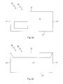
- FIG. 1 to 10 illustrated first embodiment of a device according to the invention is designated in its entirety by the reference numeral 10.
- the device 10 a vacuum unit 12.
- the vacuum unit 12 is formed in cross-section as an approximately U-shaped box 26, the underside 13 is provided with a suction port 14. At the upper end, a port 16 is provided, which connects the vacuum unit with a vacuum source 17, not shown here.
- the vacuum unit 12 further comprises a perforated conveyor belt 18, which is guided in the longitudinal direction of the suction opening 14 in a transport direction 20.
- the transport belt 18 thereby runs over rollers 22 and 24, by means of which the transport belt 18 is moved along the underside 13 of the vacuum unit 12.
- the transport belt 18 is formed as an endless transport belt.
- the device 10 serves for laminar products 28, which have a defined edge 32 at least over a certain section, to be suspended from the transport belt 18 by a negative pressure and to be transported by the latter in the transport direction 20.
- FIG Fig. 2a and 2b a letter envelope shown. This has a front 33, a back 33 ', and two side edges 37 and 37'.
- an upper edge 32 and a lower edge 35 are provided, which, viewed as a whole, surround the approximately rectangular envelope 30.
- a section of the upper edge 32 runs in a straight line, so that this envelope 30 in the in Fig. 1 and 1a shown position on this upper edge 32 adhered to the conveyor belt 18 and can be transported by this.
- the arrangement of the sheet-like products on the underside 13 of the vacuum unit according to the invention is realized so that a corresponding negative pressure is applied to the suction port 14.
- This negative pressure ensures a Sog bin.
- This suction effect has the consequence that a volume flow of air enters the intake opening 14.
- the closer design of the vacuum unit 12 in the region of the intake opening 14 is shown.
- the diaphragm element 36 has a first aperture 38 as shown in FIG Fig. 3a and 3b is shown.
- the first panel is constructed from a rectangular base body 42, which has a plurality of extending slot openings 44 and 44 'extending in the transport direction 20.
- this length of the sides corresponds to the width of the intake opening 14.
- the main body 42 is relatively thick built, for reasons of weight of a lightweight material, such as wood.
- a second panel 40 can be seen, which is substantially thinner and made of a material having a smooth surface, such as a mirror-polished stainless steel or a corresponding plastic material.
- the second panel 40 has slot openings 50 and 50 ', which are congruent with the slot openings 44 and 44' are formed. For reasons of stability, webs 58, 58 'have stopped.
- the opposite short ends 52 and 54 have the same width as the ends 46 and 48 of the first panel 38, so that the second panel 40 can be suitably placed on the first panel 38, as in the Fig. 5a and 5b is shown.
- the second panel 40 is located on the lower side of the first panel 38, ie over this second panel 40 then runs the transport belt 18. As in Fig. 5a can be seen, thus through the entire body of the diaphragm member 36 continuous suction channels 61 are formed.
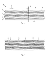
- Fig. 6 is a plan view of the conveyor belt 18 can be seen.
- the transport belt 18 has two opposite edges 62 and 64, which run parallel to the transport direction 20.
- the transport belt 18 has holes 66 as a perforation. These circular holes 66 are arranged in rows 68, wherein the five rows 68 are arranged so that they run along the channels 61 formed by the slot openings of the first and second aperture.
- Each row 68 is composed of two sub-rows 70, which are set to gap, ie the openings of a sub-row 70 are each in gaps between the openings of the adjacent sub-row 70.
- FIG. 6 represented a flat product 28 arranged with its straight edge 32 transversely to the Tarnsportcardi 20 extending or appended before, it can be seen that this upper edge 32 is in registry with a plurality of openings 66 of the perforation, which is exercised over the perforation of the Sog bin, that is the air between the upper edge 32 and the opening 66 is permanently sucked off.
- Fig. 7 It is shown how the rows 68 of the holes 66 of the conveyor belt 18 can run over the longitudinal channels 61 of the diaphragm element 36 in the transport direction. Thereby it is possible, as in Fig. 1 and 1a shown, hanging on the underside surface product 28 to move in the transport direction 20.
- the vacuum unit 12 further comprises a slider 76. This one is like that in Fig. 8 can be seen, movable in the vertical direction 78, where he, as that particular from Fig. 8a and 9th it can be seen, with the upper edge 32 of the products 28 can come into contact, especially in the section in which they look laterally beyond the vacuum unit 12.
- the slider 76 has two slide pairs 80 which can be applied on both sides of the vacuum unit 12 to the top of the block 69 and solve this from the adhesive contact with the conveyor belt 18 and the vacuum unit 12.
- Fig. 8a is exemplified as that of the entire series of products 28 of the products 28 'assembled block 69 is pushed away, which can of course also be such that the entire Row or a leading in the direction of transport 20 section is pushed away, which is so drawn only to explain the principle of operation.
- Fig. 9 is indicated that in the printing unit 12, a breaker 82 may be present. By the breaker 82 of the voltage applied to the suction port 14 negative pressure can be influenced.
- the breaker 82 In transport mode, the breaker 82 operates to provide the necessary negative pressure so that the products 28 are firmly adhered to the transport belt 18.
- the vacuum can be briefly interrupted so far via a control unit 86 and corresponding signal lines 90, 88 and 84, that the suction effect is interrupted or weakened, so that the products 28 from the transport belt 18, for example, in a Container fall off.
- the control unit 86 may receive data from any units not designated here, as indicated for example by the arrow 90. This information may be, for example, in relation to envelopes, postal codes or postal code areas, according to which the envelopes are to be divided. If, for example, a block 69 is formed from envelopes 28 'of a specific postal code area, the transport belt can be moved somewhat faster for a short time, so that a gap 71 is created for the following products 28.
- This block 69 can then be deported quite clearly from the slider 76. It is then irrelevant whether this block 69 is as long as shown or shorter.
- the slider 76 or the slider pairs 80 may also be designed so that they extend over the entire maximum length of a block to be attached. The length of the slide pairs 80 may also be variable.
- the vacuum unit 12 can be variably adapted to different products 28, that is to different widths and heavy products by either the negative pressure is varied for one, or according to other panel elements and conveyor belts are used.
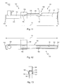
- Fig. 10 an embodiment is shown, in which the device 10 according to the invention is integrated into an overall device 100.
- the overall device 100 has a transport unit 102, which in turn has two transport elements 104 and 106. Of these transport elements 104 and 106 is in Fig. 10 only the transport element 104 recognizable.
- the transport element 104 has horizontally extending conveyor belts 108 and 110, the same applies to the transport element 106, which, viewed from the viewer, lies behind the transport element 104.
- the conveyor belts 108 and 110 rest on one of the standing side edges 37 or 37 'of the envelope 30, the conveyor belts of the second transport elements 106 then on the corresponding opposite edges.
- the envelopes 30 are aligned standing coming from a station and initially transported via their side edges 37, 37 'in the transport unit 102 in the transport direction 20 and thereby already formed into a block 69.
- the envelopes 30 reach a transition region 112. From this transition region 112, the envelopes 30 are transferred into the device 10 according to the invention.
- the envelopes 30 are initially held by the transport unit 102 at their side edges 37, 37 ', but they are then already detected at its upper edge 32 of the vacuum unit 12.
- By moving the conveyor belt 18, these are then moved further in the transport direction 20, for example via brought a transport container 114.
- the slider 76 By operating the slider 76, the products 30 can be pushed away from the vacuum unit and transferred to the transport container 114.
- the vacuum unit 122 has on its underside 123 again a longitudinally approximately rectangular suction opening 124, as well as from Fig. 12 is apparent.
- the vacuum unit 122 is connected to a vacuum source 127 via a connection 126 arranged at an end region.
- the vacuum unit 122 has a Teleskopsaugang 129, the maximum length 131 is shown.
- the Teleskopsaugruc 129 has a first telescopic rail 133 into which a second telescopic rail 135 is retractable, wherein in the second telescopic rail 135 still a third telescopic rail 137 is retractable.
- the first telescopic rail 133 is fixedly connected to an arm 139, via which the vacuum unit 122 is movable or pivotable as a complete unit.
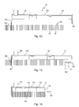
- a drive 143 is arranged, which has two laterally offset parallel spindles 145 and 147, which are accommodated in a common approximately central socket 149.
- the Teleskopsaugruc 129 in its maximum extended position 131, as in FIGS. 11 and 12 is shown, brought out of this and, as described below, in a more or less retracted position. In order not to overload the drawings with these details, this drive is only in Fig. 11 shown.
- the telescopic suction bar 129 can work without the drive 143, then you have to move the extendable end 141 by hand. It is also provided to assist the extension of the telescopic rail by a spring, so that the retraction occurs against the force of the spring. In order to be able to distribute the negative pressure exerted by the negative pressure source 127 uniformly over the entire intake opening 124 in all extended positions, corresponding suction port openings 150, 152 are provided in the second and third telescopic rails 135 and 137, respectively.
- a row 158 of standing products 28, again letter envelopes in the illustrated embodiment, is provided.
- a diverter blade 160 separates a trailing end of the row 158 from a next row.
- the vacuum unit 122 is now brought over the arm 139 over the row 158, that the immersion fork 156 is immersed from above immediately behind the separator sheet 160 in the series 158, as that from the transition from Fig. 14 to Fig. 15 is apparent.
- the Teleskopsaugruc 129 of the vacuum unit 122 is extended further than the right outer leading end of the Row 158.
- the extended end 141 By operating the drive not shown here, the extended end 141, so the dip fork 154 is applied to this outer end 162 of the row 158, as indicated by an arrow 159.
- the vacuum source 127 the row 158 is sucked, in which case in particular the air between the individual products 28 of the row 158 is sucked through the approximately rectangular suction port 124.
- the row 158 shrinks to a compressed stack 164, like that in FIG Fig. 16 is shown.
- the right end that is to say the immersion fork 154, is continuously tracked, that is to say it is thus under pressure at the right outer end 162 of the compressed stack 164.
- the vacuum unit 122 enters from above into the open end of the container 166. This may be done until the compressed stack 164 comes to rest on the floor 168 of the container 166, or it may be done by keeping it above the floor 168 at a certain distance.
- the compressed stack 164 then either slips completely onto the floor 168, or if it is already standing up, the vacuum unit 122 can be moved upwards in this state, as in FIG Fig. 18 is shown by the arrow 169.
- the compressed stack 164 slightly expands, i. In some cases, air can again enter between the individual products or, in particular, when these are folded products, they spread open again and completely fill the container 166.
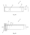
- FIGS. 19 and 20 a third embodiment of a vacuum unit 172 according to the invention is shown.
- the vacuum unit 172 consists of a U-shaped hollow profile, whose undersides of the U still each have inwardly angled edges 177. At one end of the thus formed squeegee 175 is completed. Via a suction opening 178 in the upper side, the vacuum unit 172 is connected to a vacuum source not shown here.
- a cover 176 In the interior of the squeegee 175 can laterally a cover 176 are inserted in the form of a sliding plate, as in Fig. 19 is shown by an arrow. In this case, the cover 176 rests on the inward edges 177.
- the effective cross-section of the suction opening 174 is thus determined by the longitudinal edges of the edges 177, the termination on a left side and by the position of the cover 176. The further the cover 176 is inserted, the smaller the length of the suction opening 174.
- the cover 176 also provides an airtight seal of the squeegee 175 to the right side, from which the cover 176 is inserted.
- Fig. 20 a situation is shown in which the cover 176 is pushed very far into the squeegee 175, so that only a reduced small suction port 174 remains.
- already some products 28 are arranged hanging above the upper edge of the suction opening 174.
- FIGS. 19 and 20 can be stored in different containers by sections insertion of the cover 176 gradually blocks.
- each corresponding to letter post envelopes a postal code area, attached to the bottom 173 can be replaced by each corresponding rapid advancement of the cover 176 gradually such a block and into an underlying Transport containers are delivered.
Landscapes
- Engineering & Computer Science (AREA)
- Mechanical Engineering (AREA)
- Making Paper Articles (AREA)
- Harvester Elements (AREA)
- Delivering By Means Of Belts And Rollers (AREA)
- Supplying Of Containers To The Packaging Station (AREA)
Applications Claiming Priority (1)
| Application Number | Priority Date | Filing Date | Title |
|---|---|---|---|
| DE102010032334A DE102010032334A1 (de) | 2010-07-19 | 2010-07-19 | Unterdruckfördereinrichtung |
Publications (2)
| Publication Number | Publication Date |
|---|---|
| EP2409938A2 true EP2409938A2 (fr) | 2012-01-25 |
| EP2409938A3 EP2409938A3 (fr) | 2012-12-26 |
Family
ID=44514513
Family Applications (1)
| Application Number | Title | Priority Date | Filing Date |
|---|---|---|---|
| EP11174435A Withdrawn EP2409938A3 (fr) | 2010-07-19 | 2011-07-19 | Dispositif de convoyeur à bande de dépression |
Country Status (3)
| Country | Link |
|---|---|
| US (1) | US20120012440A1 (fr) |
| EP (1) | EP2409938A3 (fr) |
| DE (1) | DE102010032334A1 (fr) |
Cited By (2)
| Publication number | Priority date | Publication date | Assignee | Title |
|---|---|---|---|---|
| EP2799373A1 (fr) * | 2013-04-30 | 2014-11-05 | Stolle Machinery Company LLC | Système de presse et son ensemble d'orifice à vide |
| EP4707200A1 (fr) * | 2024-09-09 | 2026-03-11 | H. F. Meyer Maschinenbau GmbH | Installation de traitement de récipients dotée d'un pont à vide |
Families Citing this family (4)
| Publication number | Priority date | Publication date | Assignee | Title |
|---|---|---|---|---|
| CN104128527A (zh) * | 2013-04-30 | 2014-11-05 | 斯多里机械有限责任公司 | 压机系统及其真空端口组件 |
| US20180229871A1 (en) * | 2015-06-30 | 2018-08-16 | Kimberly-Clark Worldwide, Inc. | Tissue packaging apparatus |
| EP3747808B1 (fr) | 2019-06-05 | 2023-11-15 | G.D S.p.A. | Dispositif et procédé pour alimenter des flans dans une machine de transformation ultérieure |
| CN114873239A (zh) * | 2022-04-24 | 2022-08-09 | 北新集团建材股份有限公司 | 一种自动上板机和自动上板方法 |
Family Cites Families (18)
| Publication number | Priority date | Publication date | Assignee | Title |
|---|---|---|---|---|
| US3592334A (en) * | 1966-10-27 | 1971-07-13 | Gen Logistics | Differential pressure conveyors |
| US3513972A (en) * | 1967-07-31 | 1970-05-26 | Tokyo Shibaura Electric Co | Apparatus for selecting sheet-form articles |
| FR2123097B1 (fr) * | 1970-12-23 | 1975-01-10 | Seita | |
| US3850088A (en) * | 1972-05-16 | 1974-11-26 | Itt | Slicing and filling apparatus |
| CA1060491A (fr) * | 1976-11-12 | 1979-08-14 | Steve Sarovich | Appareil a marche a vide de manutention et de mise d'aplomb des boites |
| FR2478047A1 (fr) * | 1980-03-13 | 1981-09-18 | Air Ind | Dispositif pour la manutention d'un materiau sous forme de plaque |
| US4474367A (en) * | 1982-03-08 | 1984-10-02 | The Mead Corporation | Sheet handling apparatus and method of sheet handling for selective removal of sheets from a vacuum drum |
| JPS60169148A (ja) * | 1984-02-13 | 1985-09-02 | Dainippon Screen Mfg Co Ltd | 基板の搬送方法及びその装置 |
| US4773522A (en) * | 1985-02-12 | 1988-09-27 | Meyer Conveyair, Inc. | Vacuum deadplate |
| DE3820032A1 (de) * | 1988-06-13 | 1989-12-14 | Winkler Duennebier Kg Masch | Interfolder mit den faltwalzen nachgeschalteter staustrecke |
| JPH04260516A (ja) * | 1991-02-14 | 1992-09-16 | Bridgestone Corp | タイヤ構成部材搬送装置 |
| US5829222A (en) * | 1994-06-10 | 1998-11-03 | Johnson & Johnson Vision Products, Inc. | Automated apparatus and method for consolidating products for packaging |
| US5528878A (en) * | 1994-06-10 | 1996-06-25 | Johnson & Johnson Vision Products, Inc. | Automated apparatus and method for consolidating products for packaging |
| DE9413617U1 (de) * | 1994-08-24 | 1994-10-13 | NSM Magnettechnik GmbH, 59399 Olfen | Einrichtung zum Wenden von Gegenständen, wie insbesondere Dosen oder Dosendeckeln |
| US5727832A (en) * | 1995-12-12 | 1998-03-17 | Abb Flexible Automation, Inc. | End effector for transferring articles |
| US5819907A (en) * | 1996-07-15 | 1998-10-13 | Goldco Industries, Inc. | Apparatus and method for conveying different types of force responsive articles |
| US6860531B2 (en) * | 2001-12-20 | 2005-03-01 | Abb Inc. | Gripping and vacuum end effector for transferring articles |
| US7637711B2 (en) * | 2005-02-08 | 2009-12-29 | Meadwestvaco Corporation | Apparatus with suction head for moving envelopes |
-
2010
- 2010-07-19 DE DE102010032334A patent/DE102010032334A1/de not_active Withdrawn
-
2011
- 2011-07-19 US US13/185,834 patent/US20120012440A1/en not_active Abandoned
- 2011-07-19 EP EP11174435A patent/EP2409938A3/fr not_active Withdrawn
Non-Patent Citations (1)
| Title |
|---|
| None |
Cited By (4)
| Publication number | Priority date | Publication date | Assignee | Title |
|---|---|---|---|---|
| EP2799373A1 (fr) * | 2013-04-30 | 2014-11-05 | Stolle Machinery Company LLC | Système de presse et son ensemble d'orifice à vide |
| US9550224B2 (en) | 2013-04-30 | 2017-01-24 | Stolle Machinery Company, Llc | Press system and vacuum port assembly therefor |
| US9757790B2 (en) | 2013-04-30 | 2017-09-12 | Stolle Machinery Company, Llc | Press system with vacuum port assembly |
| EP4707200A1 (fr) * | 2024-09-09 | 2026-03-11 | H. F. Meyer Maschinenbau GmbH | Installation de traitement de récipients dotée d'un pont à vide |
Also Published As
| Publication number | Publication date |
|---|---|
| US20120012440A1 (en) | 2012-01-19 |
| EP2409938A3 (fr) | 2012-12-26 |
| DE102010032334A1 (de) | 2012-01-19 |
Similar Documents
| Publication | Publication Date | Title |
|---|---|---|
| DE3636544C2 (de) | Umkehr-Kollationiermaschine | |
| EP2441574B1 (fr) | Procédé et dispositif de formation de fonds ouverts sur des zones d'extrémité de corps de sachets tubulaires | |
| EP3017940B2 (fr) | Procédé et dispositif de fabrication de sacs à partir de corps de sac tubulaires | |
| DE2315813B2 (de) | Vorrichtung zum Stapeln von bogenförmigem Material | |
| EP2409938A2 (fr) | Dispositif de convoyeur à bande de dépression | |
| DE2737244C2 (de) | Endlospapierbahn zur Herstellung von Faltbriefumschlägen mit anhängenden Einlagen | |
| EP0567807B1 (fr) | Poste de traitement actif pour un courant de produits imprimés en formation imbriquée | |
| EP0417503B1 (fr) | Procédé et dispositif pour le traitement ultérieur de produits imprimés empilés, de préférence pliés | |
| DE10229322A1 (de) | Vorrichtung zum Vereinzeln eines Schuppenstroms von Druckprodukten in eine Folge beabstandeter Druckprodukte | |
| EP1456106A1 (fr) | Procede et dispositif pour former des groupes d'objets plats | |
| EP0623458A2 (fr) | Procédé et dispositif pour appliquer un adhésif pour encoller des feuilles de papier et/ou plastique | |
| DE3602210A1 (de) | Vorrichtung zur herstellung von blocks mit mindestens einer tascheneinheit sowie tascheneinheit | |
| DE3009927A1 (de) | Einrichtung zum abbauen von mindestens zwei stapeln von biegsamen flaechengebilden, insbesondere von bogen oder druckprodukten | |
| EP2399853A2 (fr) | Dispositif de transport pour produits plats | |
| DE102015215228A1 (de) | Verfahren und Vorrichtung zum Verbinden von Etikettenschläuchen | |
| DE19855191C2 (de) | Abstapelvorrichtung für eine Ausgabeeinheit einer Druckvorrichtung | |
| EP1254857A2 (fr) | Dispositif pour assembler des articles plats en piles et pour le traitement ultérieur de la pile | |
| DE1937082C3 (de) | Verfahren und Vorrichtung zum Untereinander-Staffeln von Briefumschlägen, Beuteln oder ähnlichen Werkstücken | |
| DE2228808C2 (de) | Mehrfachfaltvorrichtung | |
| EP0415904A1 (fr) | Dispositif pour séparer des courants superposés d'articles se chevauchant | |
| EP0554524A1 (fr) | Procédé pour la fabrication de sacs et dispositif pour éxécuter ce procédé | |
| DE4141143A1 (de) | Vorrichtung zum falten und verpacken von hygieneprodukten | |
| DE102012207126A1 (de) | Vorrichtung und Verfahren zum Falten von faltbaren Zuschnitten | |
| WO2003022694A1 (fr) | Recipient pour liquides et machine permettant sa realisation | |
| EP2399854A2 (fr) | Dispositif de déviation pour produits plats |
Legal Events
| Date | Code | Title | Description |
|---|---|---|---|
| AK | Designated contracting states |
Kind code of ref document: A2 Designated state(s): AL AT BE BG CH CY CZ DE DK EE ES FI FR GB GR HR HU IE IS IT LI LT LU LV MC MK MT NL NO PL PT RO RS SE SI SK SM TR |
|
| AX | Request for extension of the european patent |
Extension state: BA ME |
|
| PUAI | Public reference made under article 153(3) epc to a published international application that has entered the european phase |
Free format text: ORIGINAL CODE: 0009012 |
|
| PUAL | Search report despatched |
Free format text: ORIGINAL CODE: 0009013 |
|
| AK | Designated contracting states |
Kind code of ref document: A3 Designated state(s): AL AT BE BG CH CY CZ DE DK EE ES FI FR GB GR HR HU IE IS IT LI LT LU LV MC MK MT NL NO PL PT RO RS SE SI SK SM TR |
|
| AX | Request for extension of the european patent |
Extension state: BA ME |
|
| RIC1 | Information provided on ipc code assigned before grant |
Ipc: B65H 31/30 20060101AFI20121121BHEP |
|
| STAA | Information on the status of an ep patent application or granted ep patent |
Free format text: STATUS: THE APPLICATION IS DEEMED TO BE WITHDRAWN |
|
| 18D | Application deemed to be withdrawn |
Effective date: 20130627 |