EP3017940B2 - Procédé et dispositif de fabrication de sacs à partir de corps de sac tubulaires - Google Patents
Procédé et dispositif de fabrication de sacs à partir de corps de sac tubulaires Download PDFInfo
- Publication number
- EP3017940B2 EP3017940B2 EP14191600.7A EP14191600A EP3017940B2 EP 3017940 B2 EP3017940 B2 EP 3017940B2 EP 14191600 A EP14191600 A EP 14191600A EP 3017940 B2 EP3017940 B2 EP 3017940B2
- Authority
- EP
- European Patent Office
- Prior art keywords
- bag bodies
- bag
- bodies
- successive
- distance
- Prior art date
- Legal status (The legal status is an assumption and is not a legal conclusion. Google has not performed a legal analysis and makes no representation as to the accuracy of the status listed.)
- Active
Links
Images


Classifications
-
- B—PERFORMING OPERATIONS; TRANSPORTING
- B31—MAKING ARTICLES OF PAPER, CARDBOARD OR MATERIAL WORKED IN A MANNER ANALOGOUS TO PAPER; WORKING PAPER, CARDBOARD OR MATERIAL WORKED IN A MANNER ANALOGOUS TO PAPER
- B31B—MAKING CONTAINERS OF PAPER, CARDBOARD OR MATERIAL WORKED IN A MANNER ANALOGOUS TO PAPER
- B31B70/00—Making flexible containers, e.g. envelopes or bags
- B31B70/02—Feeding or positioning sheets, blanks or webs
- B31B70/04—Feeding sheets or blanks
-
- B—PERFORMING OPERATIONS; TRANSPORTING
- B31—MAKING ARTICLES OF PAPER, CARDBOARD OR MATERIAL WORKED IN A MANNER ANALOGOUS TO PAPER; WORKING PAPER, CARDBOARD OR MATERIAL WORKED IN A MANNER ANALOGOUS TO PAPER
- B31B—MAKING CONTAINERS OF PAPER, CARDBOARD OR MATERIAL WORKED IN A MANNER ANALOGOUS TO PAPER
- B31B2150/00—Flexible containers made from sheets or blanks, e.g. from flattened tubes
- B31B2150/001—Flexible containers made from sheets or blanks, e.g. from flattened tubes with square or cross bottom
- B31B2150/0014—Flexible containers made from sheets or blanks, e.g. from flattened tubes with square or cross bottom having their openings facing transversally to the direction of movement
-
- B—PERFORMING OPERATIONS; TRANSPORTING
- B31—MAKING ARTICLES OF PAPER, CARDBOARD OR MATERIAL WORKED IN A MANNER ANALOGOUS TO PAPER; WORKING PAPER, CARDBOARD OR MATERIAL WORKED IN A MANNER ANALOGOUS TO PAPER
- B31B—MAKING CONTAINERS OF PAPER, CARDBOARD OR MATERIAL WORKED IN A MANNER ANALOGOUS TO PAPER
- B31B2150/00—Flexible containers made from sheets or blanks, e.g. from flattened tubes
- B31B2150/003—Flexible containers made from sheets or blanks, e.g. from flattened tubes made from tubular sheets
-
- B—PERFORMING OPERATIONS; TRANSPORTING
- B31—MAKING ARTICLES OF PAPER, CARDBOARD OR MATERIAL WORKED IN A MANNER ANALOGOUS TO PAPER; WORKING PAPER, CARDBOARD OR MATERIAL WORKED IN A MANNER ANALOGOUS TO PAPER
- B31B—MAKING CONTAINERS OF PAPER, CARDBOARD OR MATERIAL WORKED IN A MANNER ANALOGOUS TO PAPER
- B31B2160/00—Shape of flexible containers
- B31B2160/10—Shape of flexible containers rectangular and flat, i.e. without structural provision for thickness of contents
-
- B—PERFORMING OPERATIONS; TRANSPORTING
- B31—MAKING ARTICLES OF PAPER, CARDBOARD OR MATERIAL WORKED IN A MANNER ANALOGOUS TO PAPER; WORKING PAPER, CARDBOARD OR MATERIAL WORKED IN A MANNER ANALOGOUS TO PAPER
- B31B—MAKING CONTAINERS OF PAPER, CARDBOARD OR MATERIAL WORKED IN A MANNER ANALOGOUS TO PAPER
- B31B2160/00—Shape of flexible containers
- B31B2160/20—Shape of flexible containers with structural provision for thickness of contents
-
- B—PERFORMING OPERATIONS; TRANSPORTING
- B31—MAKING ARTICLES OF PAPER, CARDBOARD OR MATERIAL WORKED IN A MANNER ANALOGOUS TO PAPER; WORKING PAPER, CARDBOARD OR MATERIAL WORKED IN A MANNER ANALOGOUS TO PAPER
- B31B—MAKING CONTAINERS OF PAPER, CARDBOARD OR MATERIAL WORKED IN A MANNER ANALOGOUS TO PAPER
- B31B50/00—Making rigid or semi-rigid containers, e.g. boxes or cartons
- B31B50/02—Feeding or positioning sheets, blanks or webs
- B31B50/04—Feeding sheets or blanks
- B31B50/046—Feeding sheets or blanks involving changing orientation or changing direction of transport
-
- B—PERFORMING OPERATIONS; TRANSPORTING
- B31—MAKING ARTICLES OF PAPER, CARDBOARD OR MATERIAL WORKED IN A MANNER ANALOGOUS TO PAPER; WORKING PAPER, CARDBOARD OR MATERIAL WORKED IN A MANNER ANALOGOUS TO PAPER
- B31B—MAKING CONTAINERS OF PAPER, CARDBOARD OR MATERIAL WORKED IN A MANNER ANALOGOUS TO PAPER
- B31B70/00—Making flexible containers, e.g. envelopes or bags
- B31B70/005—Making flexible containers, e.g. envelopes or bags involving a particular layout of the machinery or relative arrangement of its subunits
Definitions
- the invention relates to a method and a device for producing sacks from tubular sack bodies, wherein the sack bodies are preferably made from a fabric made of plastic tapes or a nonwoven plastic material (e.g. plastic fleece) or a composite made of the fabric made of plastic tapes and the nonwoven plastic material or a plastic film connected to a net structure, wherein the material is optionally coated on at least one side with at least one plastic layer and/or at least one plastic film, e.g. an OPP film.
- a nonwoven plastic material e.g. plastic fleece
- OPP film e.g. an OPP film
- the sack bodies are transported on a transport device lying flat across their longitudinal extent at a transport speed in a transport direction, wherein the sack bodies pass through processing stations during their transport, with which at least one end region of each sack body is formed into a cross bottom and optionally a cover sheet is applied to the cross bottom.
- Box sacks also known as cross-bottom sacks, are cuboid-shaped sacks that are manufactured in sack-making plants by providing tubular sack bodies whose open end areas are folded into cross bottoms. The sack bodies are fed through the manufacturing plant lying flat so that two layers of the tubular sack body lie against each other. To form the bottom, the two layers are separated from each other at the end areas of the tubular sack body and one of the two layers is folded over on itself by 180° as a side flap, creating an open bottom with the other layer forming a second side flap. By folding over a layer at the end area of the tubular sack body, a triangular corner fold is created at the front and rear part of this end area.
- valve sheets can be inserted (to produce “box valve bags” that can be filled through the valve with a filling nozzle) and the final bottom configuration is produced by folding in the bottom side flaps so that they overlap.
- the overlapping bottom side flaps are glued or thermally welded together depending on the material of the bag body.
- bottom cover sheets can be placed on the overlapped bottom side flaps and glued or welded to them.
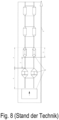
- tubular bag bodies are fed transversely to their longitudinal extension to a continuously running transport device and pass through various processing stations along their transport, such as a bottom opening device.
- a continuously running transport device Such an assembly line is in Fig. 8 shown schematically.
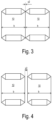
- the repeat (x) which is the distance between the front longitudinal edges or the rear longitudinal edges of two consecutive sack bodies (10)
- V transport speed
- the fixed repeat (x) results in relatively large distances (y) between the sack bodies (10), which prevent the transport potential of the sack assembly system from being fully exploited.
- DE1216196B reveals that the obvious idea of reducing the workpiece speed after the workpieces have been removed from the longitudinal conveyor area, which would also reduce the distance between the workpieces, is not implemented in practice because of the complexity and cost of the device. DE1216196B The implementation of the discussed idea is therefore explicitly discouraged. It is therefore an object of the present invention to increase the throughput of bag bodies in bag assembly systems without increasing the transport speed of the bag bodies.
- the device according to the invention and the method according to the invention for producing bags from tubular bag bodies are particularly suitable for processing bag bodies which are made from a fabric made of plastic tapes or a nonwoven plastic material (e.g. plastic fleece) or a composite made from the fabric made of plastic tapes and the nonwoven plastic material or a plastic film connected to a net structure, wherein the material is optionally coated on at least one side with at least one plastic layer and/or at least one plastic film, e.g. an OPP film.
- a nonwoven plastic material e.g. plastic fleece
- a composite made from the fabric made of plastic tapes and the nonwoven plastic material or a plastic film connected to a net structure
- the material is optionally coated on at least one side with at least one plastic layer and/or at least one plastic film, e.g. an OPP film.
- the bag bodies are transported lying flat transversely to their longitudinal extension at a transport speed in a transport direction, whereby at least one end region of the bag bodies is formed into a cross bottom during their transport and optionally a cover sheet is applied to the cross bottom.
- Sack bodies to be transported are moved by at least one transfer device by a feed distance in the transport direction in relation to sack bodies transported at transport speed and then moved at the transport speed, the movement of the sack bodies on the feed distance taking place at least in sections at a transfer speed that is greater than the transport speed.
- This measure adjusts the length of the repeat and can be set to a predefined distance between adjacent sack bodies by calculating and controlling the feed distance depending on the width of the sack bodies so that the predefined distance between successive sack bodies or between the cover sheets of successive sack bodies results. So that the device according to the invention can be operated automatically, the width of the sack bodies is detected by a sensor.
- the device comprises a control system which calculates the feed distance depending on the width of the sack bodies so that a predefined distance between successive sack bodies or between the cover sheets of successive sack bodies results.
- the controller controls the transfer device according to the calculated feed distance, wherein the controller controls the speed at which the transfer device moves the bag bodies in the transport direction according to a speed profile which includes accelerating to the transfer speed and, after a period of time dependent on the length of the feed distance, braking to the transport speed.
- the speed at which the bag bodies are moved on the feed path is controlled according to a speed profile.
- the speed profile includes accelerating to the transfer speed and, after a period of time that depends on the length of the feed path, braking to the transport speed.
- the bag assembly can be further improved and automated to an even greater extent if the cover sheet target position and the target length of the cover sheets and optionally the valve sheet target position of valve sheets are calculated based on the recorded bag width and the predefined distance between successive bag bodies and cover sheets are cut to the target length and applied to the bag bodies based on this information when they have reached the cover sheet target position and optionally the valve sheets are applied to the bag bodies when they have reached the valve sheet target position.
- the transfer device preferably has holding means for gripping, holding and releasing the bag bodies, whereby the holding means can be designed as mechanical grippers and/or vacuum suction cups.
- a control system controls the times at which the holding means grip and release the bag bodies. If at least two holding means are provided that can be moved independently of one another, it is possible to align misaligned bag bodies by means of different movements of the holding means using a suitable control system. Misalignments can be caused, for example, when the bag bodies are cut.
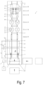
- the device 1 comprises a transport device 2 which transports the sack bodies 10 lying flat across their longitudinal extent L at a transport speed V in a transport direction T.
- the sack bodies have a front side edge 11 and a rear side edge 12, between which the width b is measured.
- Guide rails 3 hold the sack bodies 10 in the correct position on the transport device.
- the sack bodies 10 are made from a fabric made of stretched plastic tapes or a nonwoven plastic material (e.g.
- plastic fleece or a composite made from the fabric made of plastic tapes and the nonwoven plastic material or a plastic film connected to a net structure and are preferably provided with a coating made of a polymer.
- Composites can also comprise plastic films, paper layers or metal foils.
- the coating comprises a layer of an OPP film, further printing layers, etc.
- a hose 10a is fed from a storage device (not shown) or an inline hose production machine to a cross-cutting device 8, which cuts tubular bag bodies 10 from the hose 10a and feeds them to the transfer device 4 described in detail below.
- the bag bodies 10 pass through processing stations with which at least one end region 13 of each bag body 10 is formed into a cross bottom and a cover sheet 19 is applied to the cross bottom.
- the processing stations described below are formed. In other embodiments of the invention, however, not all of these processing stations are implemented, or other processing stations (quality inspection, printing device, etc.) can also be provided.
- a folding station 30 serves to fold the end regions 13 of the sack body 10 from the flat state upwards around the guide rails 3.
- a bottom opening station 40 serves to pull the two folded-up layers of the end regions 13 of the sack body 10 away from each other and to fold them over in opposite directions by 90° each, thereby creating an open bottom 17 which has two side flaps 15, 16, of which one side flap 16 is folded back by 180° onto the wall of the sack body 10. By folding over the side flaps 15, 16, a triangular corner fold 14 is created on the front and rear part of the open bottom 17.
- a valve leaf 18 is placed on the open bottom 17 of the sack body 10 and, if necessary, fixed by gluing or thermal welding.
- the final cross-bottom configuration is then produced in a bottom forming station 60 by folding in the bottom side flaps 15, 16, whereby the triangular folds 14 at the front and rear bottom end areas are reduced in size by folding in, but their triangular shape is retained. Since the side flaps 15, 16 are folded over at folding edges that are parallel to one another, the triangular folds have the shape of an isosceles triangle, the hypotenuse of which runs between the end points of the folding edges.
- the folded bottom side flaps 15, 16 are glued to one another, depending on the material of the bag body, or thermally welded if they overlap one another. However, there are also designs of bags in which the bottom side flaps 15, 16 do not overlap one another.
- a cover sheet application station 70 for applying a bottom cover sheet 19 to the folded bottom side flaps 15, 16 and a hot air welding station 80 for fixing the bottom cover sheet 19 to the folded bottom side flaps 15, 16 are also provided.
- the cover sheet application station 70 and the welding station 80 can be integrated into one another.
- an adhesive station can also be provided.
- the device 1 has a transfer device 4 to which the bag bodies 10 are fed either transversely or longitudinally.
- the transfer device 4 transfers the fed bag bodies 10 in a transverse arrangement to the transport device 2 by means of a movement in the transport direction T.
- the transfer device 4 moves bag bodies 10 to be transported in relation to bag bodies conveyed at transport speed V by a feed distance ⁇ y in the transport direction T and then transfers them to the transport device 2, wherein the transfer device 4 moves the bag bodies 10 in the transport direction T at least in sections at a transfer speed U which is greater than the transport speed V.
- the throughput of bag bodies 10 through the device 1 can be increased while maintaining the same transport speed T.
- the transfer device 4 can have holding means 4b for gripping, holding and releasing the bag bodies.
- the holding means 4b are designed as mechanical grippers which are attached to endless belts 4a running around pulleys 4c, 4d.
- One of the pulleys 4c is driven by a drive 7 which is (automatically) controlled by a controller 6 which can also control the holding means 4b.
- the holding means 4b can also be designed as vacuum suction cups.
- the feed distance ⁇ y can be calculated and changed using the controller 6.
- the controller 6 can control the speed of the drive 7 and controls the times at which the holding means 4b grip and release the bag bodies 10.
- the processing stations 30, 40, 50, 60, 70, 80 provided in the device 1 are also equipped with individual drives, switches and actuators - e.g. controlled by the control 6 - in order to be able to react to the variable bag distances.
- the connection of the control 6 with the transfer device 4 and the processing stations 30, 40, 50, 60, 70, 80 is shown in the Figures 1 and 2 not shown. This connection is either a point-to-point line (serial or parallel) or a network connection.
- the control 6 contains a computer with which the feed distance ⁇ y can be calculated as a function of the width (b) of the bag bodies 10 in such a way that a predefined distance y2 between successive bag bodies 10, 10 or between the cover sheets of successive bag bodies is obtained (distance y3, see Fig. 1 ).
- the controller 6 controls the transfer device 4 according to the calculated feed distance ⁇ y.
- a sensor 5 is provided for detecting the width b of the bag body 10.
- the sensor 5 sends the detected width b to the control 6.
- the sensor 5 can, for example, be camera-supported or detect the width b by means of light barriers.
- the feed distance ⁇ y is varied depending on the bag body width b and thus the length of the repeat is changed.
- the distance y2 between the bag bodies 10 can thus be kept constant even with different bag body widths b.
- the controller 6 controls the speed at which the transfer device 4 moves the bag bodies in the transport direction T according to a speed profile.
- This speed profile includes accelerating the picked up bag bodies, which are fed to the transfer device 4 at a speed between 0 and the transport speed V, to the transfer speed U and, after a period of time dependent on the length of the feed path ⁇ y, braking to the transport speed V.
- the controller 6 can calculate the target position and target length of the cover sheet 19 and optionally the target position of a valve sheet 18 based on the recorded bag width b and the predefined distance y2 between successive bag bodies and use this information to control the cover sheet application station 70 so that it cuts a cover sheet 19 according to the target length and applies it to the bag body 10 when it has reached the target position.
- the control 6 controls the valve sheet insertion station 50 so that it applies a valve sheet 18 to the bag body 10 when it has reached the desired position.
- the smaller distance between the bag bodies 10 also increases the efficiency of a hot-air welding device 80 for fixing the bottom cover sheets 19, since the idle time and the energy loss due to unused heat is minimized.
Landscapes
- Making Paper Articles (AREA)
Claims (13)
- Dispositif (1) de fabrication de sacs à partir de corps de sac tubulaires (10), dans lequel les corps de sac sont fabriqués de préférence à partir d'un tissu de bandelettes de plastique ou d'un matériau synthétique non tissé (p. ex. de feutre synthétique) ou d'une association de tissu de bandelettes de plastique et de matériau synthétique non tissé ou d'un film de plastique associé à une structure réticulaire, le matériau étant recouvert de manière facultative au moins sur une face par au moins une couche de plastique et/ou au moins un film de plastique, p. ex. un film OPP,avec au moins un dispositif de transport (2) qui transporte les corps de sac posés à plat perpendiculairement à leur extension longitudinale (L) à une vitesse de transport (V) dans une direction de transport (T), les corps de sac traversant pendant leur transport des stations de traitement (30, 40, 50, 60, 70, 80) dans lesquelles au moins une zone terminale (13) de chaque corps de sac est transformée en un fond croisé et, de manière facultative, une feuille de couverture (19) est posée sur le fond croisé,caractérisé par un dispositif de transmission (4) qui déplace des corps de sac (10) à transporter par le dispositif de transport par rapport à des corps de sac transportés à la vitesse de transport (V), sur un trajet d'avancée (Δy) dans la direction de transport (T) et les transmet au dispositif de transport (2), ce dispositif de transfert (4) déplaçant les corps de sac dans la direction de transport (T) au moins partiellement à une vitesse de transmission (U) qui est supérieure à la vitesse de transport (V), et caractérisé par une commande (6) qui calcule le trajet d'avancée (Δy) en fonction de la largeur (b) des corps de sac de sorte à obtenir une distance prédéfinie (y2, y3) entre les corps de sac successifs ou entre les feuilles de couverture (19) des corps de sac (10) successifs, et qui commande le dispositif de transmission (4) en fonction du trajet d'avancée (Δy) calculé, dans lequel la commande (6) contrôle la vitesse à laquelle le dispositif de transmission (4) déplace les corps de sac dans la direction de transport (T), selon un profil de vitesse qui comprend l'accélération à la vitesse de transmission (U) et, après un laps de temps dépendant du trajet d'avancée (Δy), le ralentissement à la vitesse de transport (V).
- Dispositif selon la revendication 1, caractérisé en ce que le dispositif de transmission (4) présente des moyens de retenue (4b) pour attraper, maintenir et libérer les corps de sac, les moyens de retenue comprenant de préférence des préhenseurs mécaniques et/ou des aspirateurs à vide.
- Dispositif selon la revendication 1 ou 2, caractérisé par un capteur (5) pour détecter la largeur (b) des corps de sac, qui transmet la largeur détectée à la commande (6).
- Dispositif selon les revendications 1, 2 et 3, caractérisé en ce que la commande (6) contrôle les moments où les moyens de retenue (4b) attrapent et lâchent les corps de sac.
- Dispositif selon une des revendications 3 ou 4, caractérisé en ce que la commande (6) calcule à l'aide de la largeur de sac (b) détectée et de la distance prédéfinie (y2) entre les corps de sac successifs, la position nominale et la longueur nominale de la feuille de couverture (19), ainsi que, de manière facultative, la position nominale d'une feuille à valve (18) et, à l'aide de ces informations, commande une station de pose de feuilles de couverture (70) afin qu'elle découpe une feuille de couverture (19) conformément à la longueur nominale et la pose sur le corps de sac lorsqu'il a atteint la position nominale de la feuille de couverture, et, de manière facultative, commande une station d'insertion de feuilles à valve (50) afin qu'elle pose une feuille à valve (18) sur le corps de sac lorsqu'il a atteint la position nominale de la feuille à valve.
- Dispositif selon une des revendications précédentes, caractérisé en ce que le trajet d'avancée (Δy) est choisi de sorte à obtenir une distance prédéfinie (y2) de 0 à 5 cm entre les corps de sac successifs.
- Dispositif selon une des revendications 1 à 5, caractérisé en ce que le trajet d'avancée (Δy) est choisi de sorte à ce que les corps de sac successifs se chevauchent, la largeur du chevauchement correspondant de préférence à la hauteur (h) ou au double de la hauteur du rabat de coin triangulaire (14) qui apparaît lorsque les rabats latéraux du fond (15, 16) sont pliés, dans ce dernier cas une section longitudinale (10b) d'au moins un des corps de sacs successifs orientée vers l'autre corps de sac et dotée d'une largeur qui correspond à la hauteur (h) du rabat de coin étant rabattue.
- Dispositif selon une des revendications 2 à 7, caractérisé en ce que sont prévus au moins deux moyens de retenue (4b) qui sont mobiles indépendamment l'un de l'autre.
- Procédé de fabrication de sacs à partir de corps de sac tubulaires (10), dans lequel les corps de sac sont fabriqués de préférence à partir d'un tissu de bandelettes de plastique ou d'un matériau synthétique non tissé (p. ex. de feutre synthétique) ou d'une association de tissu de bandelettes de plastique et de matériau synthétique non tissé ou d'un film de plastique associé à une structure réticulaire, le matériau étant recouvert de manière facultative au moins sur une face par au moins une couche de plastique et/ou au moins un film de plastique, p. ex. un film OPP,dans lequel les corps de sac sont transportés à plat perpendiculairement à leur extension longitudinale (L) à une vitesse de transport (V) dans une direction de transport (T), au moins une zone terminale (13) des corps de sac étant transformée pendant leur transport en un fond croisé et, de manière facultative, une feuille de couverture (19) étant posée sur le fond croisé,caractérisé en ce que des corps de sac (10) à transporter par rapport à des corps de sac transportés à la vitesse de transport (V), sont déplacés sur un trajet d'avancée (Δy) dans la direction de transport (T) et ensuite déplacés à la vitesse de transport (V), le déplacement des corps de sac sur le trajet d'avancée (Δy) se faisant au moins partiellement à une vitesse de transmission (U) qui est supérieure à la vitesse de transport (V), et caractérisé en ce que le trajet d'avancée (Δy) est calculé en fonction de la largeur (b) des corps de sac de sorte à obtenir une distance prédéfinie (y2, y3) entre les corps de sac (10) successifs ou entre les feuilles de couverture (19) des corps de sac successifs, et que le déplacement des corps de sac est commandé en fonction du trajet d'avancée (Δy) calculé, dans lequel la vitesse à laquelle les corps de sac sont déplacés sur le trajet d'avancée (Δy) est commandée selon un profil de vitesse qui comprend l'accélération à la vitesse de transmission (U) et, après un laps de temps dépendant du trajet d'avancée (Δy), le ralentissement à la vitesse de transport (V).
- Procédé selon la revendication 9, caractérisé en ce que la largeur (b) des corps de sac est détectée par un capteur (5).
- Procédé selon la revendication 10, caractérisé en ce que la position nominale et la longueur nominale des feuilles de couverture (19), ainsi que, de manière facultative, la position nominale de feuilles à valve (18) sont calculées à l'aide de la largeur de sac (b) détectée et de la distance prédéfinie (y2) entre les corps de sac successifs, et, qu'à l'aide de ces informations, les feuilles de couverture (19) sont découpées conformément à la longueur nominale et posées sur les corps de sac (10) lorsqu'ils ont atteint la position nominale des feuilles de couverture, et, de manière facultative, les feuilles à valve (18) sont posées sur les corps de sac lorsqu'ils ont atteint la position nominale des feuilles à valve.
- Procédé selon une des revendications 9 à 11, caractérisé en ce que le trajet d'avancée (Δy) est choisi de sorte à obtenir une distance prédéfinie (y2) de 0 à 5 cm entre les corps de sac successifs.
- Procédé selon une des revendications 9 à 11, caractérisé en ce que le trajet d'avancée (Δy) est choisi de sorte à ce que les corps de sac successifs se chevauchent, la largeur du chevauchement correspondant de préférence à la hauteur (h) ou au double de la hauteur du rabat de coin triangulaire (14) qui apparaît lorsque les rabats latéraux du fond (15, 16) sont pliés, dans ce dernier cas une section longitudinale (10b) d'au moins un des corps de sacs successifs orientée vers l'autre corps de sac et dotée d'une largeur qui correspond à la hauteur (h) du rabat de coin étant rabattue.
Priority Applications (5)
| Application Number | Priority Date | Filing Date | Title |
|---|---|---|---|
| EP14191600.7A EP3017940B2 (fr) | 2014-11-04 | 2014-11-04 | Procédé et dispositif de fabrication de sacs à partir de corps de sac tubulaires |
| BR112017007870-8A BR112017007870B1 (pt) | 2014-11-04 | 2015-11-02 | Dispositivo e método para produzir sacos a partir de corpos de saco tubulares |
| CN201910447922.XA CN110154448B (zh) | 2014-11-04 | 2015-11-02 | 用于从管状袋体生产袋子的方法和装置 |
| CN201580059770.6A CN107073862B (zh) | 2014-11-04 | 2015-11-02 | 用于从管状袋体生产袋子的方法和装置 |
| PCT/EP2015/075409 WO2016071261A1 (fr) | 2014-11-04 | 2015-11-02 | Procédé et dispositif de fabrication de sacs à partir de corps de sac tubulaires |
Applications Claiming Priority (1)
| Application Number | Priority Date | Filing Date | Title |
|---|---|---|---|
| EP14191600.7A EP3017940B2 (fr) | 2014-11-04 | 2014-11-04 | Procédé et dispositif de fabrication de sacs à partir de corps de sac tubulaires |
Publications (3)
| Publication Number | Publication Date |
|---|---|
| EP3017940A1 EP3017940A1 (fr) | 2016-05-11 |
| EP3017940B1 EP3017940B1 (fr) | 2017-09-13 |
| EP3017940B2 true EP3017940B2 (fr) | 2024-11-20 |
Family
ID=51868049
Family Applications (1)
| Application Number | Title | Priority Date | Filing Date |
|---|---|---|---|
| EP14191600.7A Active EP3017940B2 (fr) | 2014-11-04 | 2014-11-04 | Procédé et dispositif de fabrication de sacs à partir de corps de sac tubulaires |
Country Status (4)
| Country | Link |
|---|---|
| EP (1) | EP3017940B2 (fr) |
| CN (2) | CN107073862B (fr) |
| BR (1) | BR112017007870B1 (fr) |
| WO (1) | WO2016071261A1 (fr) |
Families Citing this family (10)
| Publication number | Priority date | Publication date | Assignee | Title |
|---|---|---|---|---|
| HUE051912T2 (hu) * | 2017-12-14 | 2021-04-28 | Starlinger & Co Gmbh | Zsák ömlesztett anyagok számára |
| JP7301060B2 (ja) * | 2018-09-19 | 2023-06-30 | 株式会社フジシールインターナショナル | パウチ容器の製造方法および製造装置 |
| ES2857910T3 (es) * | 2018-12-17 | 2021-09-29 | Starlinger & Co Gmbh | Dispositivo y procedimiento para aplicar hojas de recubrimiento sobre extremos preformados para dar fondos cruzados de secciones de manguera |
| CN110385891B (zh) * | 2019-07-04 | 2021-07-20 | 河北盛世锦唐包装有限公司 | 一种新型方底阀口袋制袋机 |
| EP4017808A4 (fr) * | 2019-08-24 | 2023-10-25 | Lohia Corp Limited | Procédé et appareil de formation de sac |
| CN111619162B (zh) * | 2020-04-16 | 2021-08-20 | 西安市洁美塑业有限责任公司 | 一种阀口袋生产用热粘封底机 |
| MA62366B1 (fr) * | 2021-02-19 | 2024-03-29 | Lohia Corp Ltd | Système et procédé de transfert de pièces découpées de matériau en bande tournant les angles |
| AT524968B1 (de) * | 2021-04-29 | 2022-12-15 | Starlinger & Co Gmbh | Vorrichtung und Verfahren zur Herstellung von Säcken aus Schlauchstücken |
| DE102021134238B3 (de) | 2021-12-22 | 2023-05-04 | Mondi Ag | Verfahren zum Herstellen von Papiersäcken und Papiersäcke |
| CN118913051B (zh) * | 2024-08-15 | 2025-05-09 | 山东真光新材料科技有限公司 | 一种编织袋长宽检测装置 |
Citations (1)
| Publication number | Priority date | Publication date | Assignee | Title |
|---|---|---|---|---|
| WO2015032486A1 (fr) † | 2013-09-04 | 2015-03-12 | Windmöller & Hölscher Kg | Procédé et dispositif de fabrication de sacs à fond croisé |
Family Cites Families (13)
| Publication number | Priority date | Publication date | Assignee | Title |
|---|---|---|---|---|
| DE1216196B (de) * | 1963-10-28 | 1966-05-05 | Windmoeller & Hoelscher | Verfahren und Vorrichtung zum UEberfuehren von zu Saecken zu verarbeitenden Schlauchabschnitten aus der Laengs- in die Querfoerderung |
| SE346499B (fr) * | 1970-12-14 | 1972-07-10 | Orebro Pappersbruks Ab | |
| DE2606391A1 (de) * | 1976-02-18 | 1977-08-25 | Wilhelmstal Werke Gmbh | Transportbahn, insbesondere an maschinen zum herstellen von papiersaecken |
| DE3568762D1 (en) * | 1985-01-04 | 1989-04-20 | Librawerk Pelz & Nagel Kg | Device for picking up single spread out fabrics, preferably plastic fabrics |
| CZ289183B6 (cs) | 1995-01-25 | 2001-11-14 | Windmöller & Hölscher | Zařízení na vytahování konců plochých hadicových odřezků |
| DE50109966D1 (de) * | 2001-07-16 | 2006-07-06 | Grapha Holding Ag | Anordnung zum Bilden eines dritten Stromes aus einem ersten und einem zweiten Strom aus Druckprodukten |
| DE102008017442B4 (de) * | 2008-04-03 | 2013-01-17 | Windmöller & Hölscher Kg | Vorrichtung und Verfahren zur Herstellung von Säcken, welche Gewebe aus gereckten Kunststoffbändchen umfassen |
| DE102008017445A1 (de) * | 2008-04-03 | 2009-10-15 | Windmöller & Hölscher Kg | Vorrichtung und Verfahren zur Herstellung von Säcken |
| DE102008017443B4 (de) * | 2008-04-03 | 2014-05-28 | Windmöller & Hölscher Kg | Vorrichtung und Verfahren zur Herstellung von Säcken aus Schlauchstücken |
| DE102009000893B4 (de) * | 2008-07-31 | 2015-03-19 | Windmöller & Hölscher Kg | Verfahren und Vorrichtung zum Transport von flachen Werkstücken |
| EP2383109B1 (fr) * | 2008-11-13 | 2017-06-14 | Totani Corporation | Machine à fabriquer des sacs |
| EP2441574B1 (fr) | 2010-10-14 | 2013-05-15 | Starlinger & Co Gesellschaft m.b.H. | Procédé et dispositif de formation de fonds ouverts sur des zones d'extrémité de corps de sachets tubulaires |
| ES2599622T3 (es) | 2012-09-24 | 2017-02-02 | Starlinger & Co. Gesellschaft M.B.H. | Procedimiento y dispositivo para el transporte de piezas de trabajo planas |
-
2014
- 2014-11-04 EP EP14191600.7A patent/EP3017940B2/fr active Active
-
2015
- 2015-11-02 BR BR112017007870-8A patent/BR112017007870B1/pt active IP Right Grant
- 2015-11-02 CN CN201580059770.6A patent/CN107073862B/zh not_active Expired - Fee Related
- 2015-11-02 CN CN201910447922.XA patent/CN110154448B/zh active Active
- 2015-11-02 WO PCT/EP2015/075409 patent/WO2016071261A1/fr not_active Ceased
Patent Citations (1)
| Publication number | Priority date | Publication date | Assignee | Title |
|---|---|---|---|---|
| WO2015032486A1 (fr) † | 2013-09-04 | 2015-03-12 | Windmöller & Hölscher Kg | Procédé et dispositif de fabrication de sacs à fond croisé |
Also Published As
| Publication number | Publication date |
|---|---|
| BR112017007870B1 (pt) | 2022-02-01 |
| EP3017940A1 (fr) | 2016-05-11 |
| WO2016071261A1 (fr) | 2016-05-12 |
| CN110154448A (zh) | 2019-08-23 |
| CN110154448B (zh) | 2022-01-21 |
| EP3017940B1 (fr) | 2017-09-13 |
| CN107073862A (zh) | 2017-08-18 |
| CN107073862B (zh) | 2019-06-21 |
| BR112017007870A2 (pt) | 2018-01-23 |
Similar Documents
| Publication | Publication Date | Title |
|---|---|---|
| EP3017940B2 (fr) | Procédé et dispositif de fabrication de sacs à partir de corps de sac tubulaires | |
| EP3219646B1 (fr) | Installation de fabrication d'un produit médical et son procédé de fonctionnement | |
| EP2441574B1 (fr) | Procédé et dispositif de formation de fonds ouverts sur des zones d'extrémité de corps de sachets tubulaires | |
| DE102009000893B4 (de) | Verfahren und Vorrichtung zum Transport von flachen Werkstücken | |
| EP2409938A2 (fr) | Dispositif de convoyeur à bande de dépression | |
| EP3041672B1 (fr) | Dispositif de fabrication de sacs | |
| DE102013014732B4 (de) | Verfahren und Vorrichtung zur Herstellung von Kreuzboden-Säcken | |
| DE102015215228A1 (de) | Verfahren und Vorrichtung zum Verbinden von Etikettenschläuchen | |
| EP2248721B1 (fr) | Dispositif et procédé d'emballage d'objets | |
| DE102008017443B4 (de) | Vorrichtung und Verfahren zur Herstellung von Säcken aus Schlauchstücken | |
| EP0925910B1 (fr) | Procédé et dispositif pour la formation de piles de sacs faits à partir d'une feuille continue en plastique, en particulier de sacs pourvus d'une poignée. | |
| WO2009121542A1 (fr) | Équipement et procédé de fabrication de sacs à partir de tronçons de tube souple | |
| EP3159151B1 (fr) | Empileur et procédé destiné à empiler au moins partiellement des sacs, des sachets ou similaires | |
| EP2711165B1 (fr) | Dispositif d'acheminement pour corps de sachet | |
| AT524968B1 (de) | Vorrichtung und Verfahren zur Herstellung von Säcken aus Schlauchstücken | |
| EP2344328B1 (fr) | Procédé et appareillage pour la post-transformation de semi-produits de type sac | |
| EP3702157B1 (fr) | Procédé et dispositif de placement exact de feuilles | |
| EP4001137B1 (fr) | Procédé de manipulation de matière d'emballage en forme de bande | |
| DE4020847A1 (de) | Verfahren und vorrichtung zum etikettieren von gegenstaenden | |
| EP3532271B1 (fr) | Amélioration de la fabrication de sachets à rabat | |
| DE102013206858B4 (de) | Verfahren und Vorrichtung zum Banderolieren von Kleinfalzungen | |
| DE2425090B2 (de) | Verfahren und vorrichtung zum bilden von stapeln aus kontinuierlich zugefuehrten flachen, faltbaren werkstuecken | |
| DE29724511U1 (de) | Vorrichtung zum stapelweisen Ablegen von Beuteln aus einer Kunststoffolienbahn, insbesondere Schlaufengriff-Tragetaschen |
Legal Events
| Date | Code | Title | Description |
|---|---|---|---|
| PUAI | Public reference made under article 153(3) epc to a published international application that has entered the european phase |
Free format text: ORIGINAL CODE: 0009012 |
|
| AK | Designated contracting states |
Kind code of ref document: A1 Designated state(s): AL AT BE BG CH CY CZ DE DK EE ES FI FR GB GR HR HU IE IS IT LI LT LU LV MC MK MT NL NO PL PT RO RS SE SI SK SM TR |
|
| AX | Request for extension of the european patent |
Extension state: BA ME |
|
| STAA | Information on the status of an ep patent application or granted ep patent |
Free format text: STATUS: REQUEST FOR EXAMINATION WAS MADE |
|
| 17P | Request for examination filed |
Effective date: 20161109 |
|
| RBV | Designated contracting states (corrected) |
Designated state(s): AL AT BE BG CH CY CZ DE DK EE ES FI FR GB GR HR HU IE IS IT LI LT LU LV MC MK MT NL NO PL PT RO RS SE SI SK SM TR |
|
| REG | Reference to a national code |
Ref country code: DE Ref legal event code: R079 Ref document number: 502014005425 Country of ref document: DE Free format text: PREVIOUS MAIN CLASS: B31B0029000000 Ipc: B31B0070000000 |
|
| GRAP | Despatch of communication of intention to grant a patent |
Free format text: ORIGINAL CODE: EPIDOSNIGR1 |
|
| STAA | Information on the status of an ep patent application or granted ep patent |
Free format text: STATUS: GRANT OF PATENT IS INTENDED |
|
| RIC1 | Information provided on ipc code assigned before grant |
Ipc: B31B 70/00 20170101AFI20170424BHEP |
|
| INTG | Intention to grant announced |
Effective date: 20170526 |
|
| GRAS | Grant fee paid |
Free format text: ORIGINAL CODE: EPIDOSNIGR3 |
|
| GRAA | (expected) grant |
Free format text: ORIGINAL CODE: 0009210 |
|
| STAA | Information on the status of an ep patent application or granted ep patent |
Free format text: STATUS: THE PATENT HAS BEEN GRANTED |
|
| AK | Designated contracting states |
Kind code of ref document: B1 Designated state(s): AL AT BE BG CH CY CZ DE DK EE ES FI FR GB GR HR HU IE IS IT LI LT LU LV MC MK MT NL NO PL PT RO RS SE SI SK SM TR |
|
| REG | Reference to a national code |
Ref country code: GB Ref legal event code: FG4D Free format text: NOT ENGLISH |
|
| REG | Reference to a national code |
Ref country code: CH Ref legal event code: EP |
|
| REG | Reference to a national code |
Ref country code: IE Ref legal event code: FG4D Free format text: LANGUAGE OF EP DOCUMENT: GERMAN |
|
| REG | Reference to a national code |
Ref country code: AT Ref legal event code: REF Ref document number: 927721 Country of ref document: AT Kind code of ref document: T Effective date: 20171015 |
|
| REG | Reference to a national code |
Ref country code: DE Ref legal event code: R096 Ref document number: 502014005425 Country of ref document: DE |
|
| REG | Reference to a national code |
Ref country code: NL Ref legal event code: MP Effective date: 20170913 |
|
| REG | Reference to a national code |
Ref country code: LT Ref legal event code: MG4D |
|
| PG25 | Lapsed in a contracting state [announced via postgrant information from national office to epo] |
Ref country code: NO Free format text: LAPSE BECAUSE OF FAILURE TO SUBMIT A TRANSLATION OF THE DESCRIPTION OR TO PAY THE FEE WITHIN THE PRESCRIBED TIME-LIMIT Effective date: 20171213 Ref country code: LT Free format text: LAPSE BECAUSE OF FAILURE TO SUBMIT A TRANSLATION OF THE DESCRIPTION OR TO PAY THE FEE WITHIN THE PRESCRIBED TIME-LIMIT Effective date: 20170913 Ref country code: HR Free format text: LAPSE BECAUSE OF FAILURE TO SUBMIT A TRANSLATION OF THE DESCRIPTION OR TO PAY THE FEE WITHIN THE PRESCRIBED TIME-LIMIT Effective date: 20170913 Ref country code: FI Free format text: LAPSE BECAUSE OF FAILURE TO SUBMIT A TRANSLATION OF THE DESCRIPTION OR TO PAY THE FEE WITHIN THE PRESCRIBED TIME-LIMIT Effective date: 20170913 Ref country code: SE Free format text: LAPSE BECAUSE OF FAILURE TO SUBMIT A TRANSLATION OF THE DESCRIPTION OR TO PAY THE FEE WITHIN THE PRESCRIBED TIME-LIMIT Effective date: 20170913 |
|
| PG25 | Lapsed in a contracting state [announced via postgrant information from national office to epo] |
Ref country code: GR Free format text: LAPSE BECAUSE OF FAILURE TO SUBMIT A TRANSLATION OF THE DESCRIPTION OR TO PAY THE FEE WITHIN THE PRESCRIBED TIME-LIMIT Effective date: 20171214 Ref country code: ES Free format text: LAPSE BECAUSE OF FAILURE TO SUBMIT A TRANSLATION OF THE DESCRIPTION OR TO PAY THE FEE WITHIN THE PRESCRIBED TIME-LIMIT Effective date: 20170913 Ref country code: RS Free format text: LAPSE BECAUSE OF FAILURE TO SUBMIT A TRANSLATION OF THE DESCRIPTION OR TO PAY THE FEE WITHIN THE PRESCRIBED TIME-LIMIT Effective date: 20170913 Ref country code: LV Free format text: LAPSE BECAUSE OF FAILURE TO SUBMIT A TRANSLATION OF THE DESCRIPTION OR TO PAY THE FEE WITHIN THE PRESCRIBED TIME-LIMIT Effective date: 20170913 Ref country code: BG Free format text: LAPSE BECAUSE OF FAILURE TO SUBMIT A TRANSLATION OF THE DESCRIPTION OR TO PAY THE FEE WITHIN THE PRESCRIBED TIME-LIMIT Effective date: 20171213 |
|
| PG25 | Lapsed in a contracting state [announced via postgrant information from national office to epo] |
Ref country code: NL Free format text: LAPSE BECAUSE OF FAILURE TO SUBMIT A TRANSLATION OF THE DESCRIPTION OR TO PAY THE FEE WITHIN THE PRESCRIBED TIME-LIMIT Effective date: 20170913 |
|
| PG25 | Lapsed in a contracting state [announced via postgrant information from national office to epo] |
Ref country code: PL Free format text: LAPSE BECAUSE OF FAILURE TO SUBMIT A TRANSLATION OF THE DESCRIPTION OR TO PAY THE FEE WITHIN THE PRESCRIBED TIME-LIMIT Effective date: 20170913 Ref country code: RO Free format text: LAPSE BECAUSE OF FAILURE TO SUBMIT A TRANSLATION OF THE DESCRIPTION OR TO PAY THE FEE WITHIN THE PRESCRIBED TIME-LIMIT Effective date: 20170913 |
|
| PG25 | Lapsed in a contracting state [announced via postgrant information from national office to epo] |
Ref country code: IT Free format text: LAPSE BECAUSE OF FAILURE TO SUBMIT A TRANSLATION OF THE DESCRIPTION OR TO PAY THE FEE WITHIN THE PRESCRIBED TIME-LIMIT Effective date: 20170913 Ref country code: EE Free format text: LAPSE BECAUSE OF FAILURE TO SUBMIT A TRANSLATION OF THE DESCRIPTION OR TO PAY THE FEE WITHIN THE PRESCRIBED TIME-LIMIT Effective date: 20170913 Ref country code: SM Free format text: LAPSE BECAUSE OF FAILURE TO SUBMIT A TRANSLATION OF THE DESCRIPTION OR TO PAY THE FEE WITHIN THE PRESCRIBED TIME-LIMIT Effective date: 20170913 Ref country code: IS Free format text: LAPSE BECAUSE OF FAILURE TO SUBMIT A TRANSLATION OF THE DESCRIPTION OR TO PAY THE FEE WITHIN THE PRESCRIBED TIME-LIMIT Effective date: 20180113 Ref country code: SK Free format text: LAPSE BECAUSE OF FAILURE TO SUBMIT A TRANSLATION OF THE DESCRIPTION OR TO PAY THE FEE WITHIN THE PRESCRIBED TIME-LIMIT Effective date: 20170913 |
|
| REG | Reference to a national code |
Ref country code: DE Ref legal event code: R026 Ref document number: 502014005425 Country of ref document: DE |
|
| PLBI | Opposition filed |
Free format text: ORIGINAL CODE: 0009260 |
|
| PLAX | Notice of opposition and request to file observation + time limit sent |
Free format text: ORIGINAL CODE: EPIDOSNOBS2 |
|
| PG25 | Lapsed in a contracting state [announced via postgrant information from national office to epo] |
Ref country code: MC Free format text: LAPSE BECAUSE OF FAILURE TO SUBMIT A TRANSLATION OF THE DESCRIPTION OR TO PAY THE FEE WITHIN THE PRESCRIBED TIME-LIMIT Effective date: 20170913 |
|
| 26 | Opposition filed |
Opponent name: WINDMOELLER & HOELSCHER KG Effective date: 20180613 |
|
| PG25 | Lapsed in a contracting state [announced via postgrant information from national office to epo] |
Ref country code: DK Free format text: LAPSE BECAUSE OF FAILURE TO SUBMIT A TRANSLATION OF THE DESCRIPTION OR TO PAY THE FEE WITHIN THE PRESCRIBED TIME-LIMIT Effective date: 20170913 Ref country code: LI Free format text: LAPSE BECAUSE OF NON-PAYMENT OF DUE FEES Effective date: 20171130 Ref country code: CH Free format text: LAPSE BECAUSE OF NON-PAYMENT OF DUE FEES Effective date: 20171130 |
|
| PG25 | Lapsed in a contracting state [announced via postgrant information from national office to epo] |
Ref country code: LU Free format text: LAPSE BECAUSE OF NON-PAYMENT OF DUE FEES Effective date: 20171104 |
|
| REG | Reference to a national code |
Ref country code: FR Ref legal event code: ST Effective date: 20180731 Ref country code: BE Ref legal event code: MM Effective date: 20171130 |
|
| REG | Reference to a national code |
Ref country code: IE Ref legal event code: MM4A |
|
| PG25 | Lapsed in a contracting state [announced via postgrant information from national office to epo] |
Ref country code: MT Free format text: LAPSE BECAUSE OF FAILURE TO SUBMIT A TRANSLATION OF THE DESCRIPTION OR TO PAY THE FEE WITHIN THE PRESCRIBED TIME-LIMIT Effective date: 20170913 |
|
| PLBB | Reply of patent proprietor to notice(s) of opposition received |
Free format text: ORIGINAL CODE: EPIDOSNOBS3 |
|
| PG25 | Lapsed in a contracting state [announced via postgrant information from national office to epo] |
Ref country code: IE Free format text: LAPSE BECAUSE OF NON-PAYMENT OF DUE FEES Effective date: 20171104 Ref country code: FR Free format text: LAPSE BECAUSE OF NON-PAYMENT OF DUE FEES Effective date: 20171130 |
|
| PG25 | Lapsed in a contracting state [announced via postgrant information from national office to epo] |
Ref country code: SI Free format text: LAPSE BECAUSE OF FAILURE TO SUBMIT A TRANSLATION OF THE DESCRIPTION OR TO PAY THE FEE WITHIN THE PRESCRIBED TIME-LIMIT Effective date: 20170913 Ref country code: BE Free format text: LAPSE BECAUSE OF NON-PAYMENT OF DUE FEES Effective date: 20171130 |
|
| PG25 | Lapsed in a contracting state [announced via postgrant information from national office to epo] |
Ref country code: HU Free format text: LAPSE BECAUSE OF FAILURE TO SUBMIT A TRANSLATION OF THE DESCRIPTION OR TO PAY THE FEE WITHIN THE PRESCRIBED TIME-LIMIT; INVALID AB INITIO Effective date: 20141104 |
|
| GBPC | Gb: european patent ceased through non-payment of renewal fee |
Effective date: 20181104 |
|
| PG25 | Lapsed in a contracting state [announced via postgrant information from national office to epo] |
Ref country code: CY Free format text: LAPSE BECAUSE OF FAILURE TO SUBMIT A TRANSLATION OF THE DESCRIPTION OR TO PAY THE FEE WITHIN THE PRESCRIBED TIME-LIMIT Effective date: 20170913 |
|
| PG25 | Lapsed in a contracting state [announced via postgrant information from national office to epo] |
Ref country code: MK Free format text: LAPSE BECAUSE OF FAILURE TO SUBMIT A TRANSLATION OF THE DESCRIPTION OR TO PAY THE FEE WITHIN THE PRESCRIBED TIME-LIMIT Effective date: 20170913 |
|
| PG25 | Lapsed in a contracting state [announced via postgrant information from national office to epo] |
Ref country code: GB Free format text: LAPSE BECAUSE OF NON-PAYMENT OF DUE FEES Effective date: 20181104 |
|
| APBM | Appeal reference recorded |
Free format text: ORIGINAL CODE: EPIDOSNREFNO |
|
| APBP | Date of receipt of notice of appeal recorded |
Free format text: ORIGINAL CODE: EPIDOSNNOA2O |
|
| APAH | Appeal reference modified |
Free format text: ORIGINAL CODE: EPIDOSCREFNO |
|
| APBQ | Date of receipt of statement of grounds of appeal recorded |
Free format text: ORIGINAL CODE: EPIDOSNNOA3O |
|
| PG25 | Lapsed in a contracting state [announced via postgrant information from national office to epo] |
Ref country code: TR Free format text: LAPSE BECAUSE OF FAILURE TO SUBMIT A TRANSLATION OF THE DESCRIPTION OR TO PAY THE FEE WITHIN THE PRESCRIBED TIME-LIMIT Effective date: 20170913 |
|
| PG25 | Lapsed in a contracting state [announced via postgrant information from national office to epo] |
Ref country code: PT Free format text: LAPSE BECAUSE OF FAILURE TO SUBMIT A TRANSLATION OF THE DESCRIPTION OR TO PAY THE FEE WITHIN THE PRESCRIBED TIME-LIMIT Effective date: 20170913 |
|
| PG25 | Lapsed in a contracting state [announced via postgrant information from national office to epo] |
Ref country code: AL Free format text: LAPSE BECAUSE OF FAILURE TO SUBMIT A TRANSLATION OF THE DESCRIPTION OR TO PAY THE FEE WITHIN THE PRESCRIBED TIME-LIMIT Effective date: 20170913 |
|
| APBU | Appeal procedure closed |
Free format text: ORIGINAL CODE: EPIDOSNNOA9O |
|
| P01 | Opt-out of the competence of the unified patent court (upc) registered |
Effective date: 20230526 |
|
| PLAY | Examination report in opposition despatched + time limit |
Free format text: ORIGINAL CODE: EPIDOSNORE2 |
|
| PLBC | Reply to examination report in opposition received |
Free format text: ORIGINAL CODE: EPIDOSNORE3 |
|
| PLAY | Examination report in opposition despatched + time limit |
Free format text: ORIGINAL CODE: EPIDOSNORE2 |
|
| RIC2 | Information provided on ipc code assigned after grant |
Ipc: B31B 160/20 20170101ALN20240304BHEP Ipc: B31B 160/10 20170101ALN20240304BHEP Ipc: B31B 150/00 20170101ALN20240304BHEP Ipc: B31B 50/04 20170101ALN20240304BHEP Ipc: B31B 70/04 20170101ALI20240304BHEP Ipc: B31B 70/00 20170101AFI20240304BHEP |
|
| PUAH | Patent maintained in amended form |
Free format text: ORIGINAL CODE: 0009272 |
|
| STAA | Information on the status of an ep patent application or granted ep patent |
Free format text: STATUS: PATENT MAINTAINED AS AMENDED |
|
| 27A | Patent maintained in amended form |
Effective date: 20241120 |
|
| AK | Designated contracting states |
Kind code of ref document: B2 Designated state(s): AL AT BE BG CH CY CZ DE DK EE ES FI FR GB GR HR HU IE IS IT LI LT LU LV MC MK MT NL NO PL PT RO RS SE SI SK SM TR |
|
| REG | Reference to a national code |
Ref country code: DE Ref legal event code: R102 Ref document number: 502014005425 Country of ref document: DE |
|
| PGFP | Annual fee paid to national office [announced via postgrant information from national office to epo] |
Ref country code: CZ Payment date: 20241022 Year of fee payment: 11 |
|
| PG25 | Lapsed in a contracting state [announced via postgrant information from national office to epo] |
Ref country code: CZ Free format text: LAPSE BECAUSE OF FAILURE TO SUBMIT A TRANSLATION OF THE DESCRIPTION OR TO PAY THE FEE WITHIN THE PRESCRIBED TIME-LIMIT Effective date: 20170913 |
|
| PGFP | Annual fee paid to national office [announced via postgrant information from national office to epo] |
Ref country code: DE Payment date: 20251118 Year of fee payment: 12 |
|
| PGFP | Annual fee paid to national office [announced via postgrant information from national office to epo] |
Ref country code: AT Payment date: 20251117 Year of fee payment: 12 |