EP2410088A1 - Centrale vapeur éliminant le tartre de calcaire - Google Patents
Centrale vapeur éliminant le tartre de calcaire Download PDFInfo
- Publication number
- EP2410088A1 EP2410088A1 EP10753091A EP10753091A EP2410088A1 EP 2410088 A1 EP2410088 A1 EP 2410088A1 EP 10753091 A EP10753091 A EP 10753091A EP 10753091 A EP10753091 A EP 10753091A EP 2410088 A1 EP2410088 A1 EP 2410088A1
- Authority
- EP
- European Patent Office
- Prior art keywords
- switch
- circuit board
- control circuit
- control
- boiler
- Prior art date
- Legal status (The legal status is an assumption and is not a legal conclusion. Google has not performed a legal analysis and makes no representation as to the accuracy of the status listed.)
- Withdrawn
Links
- XLYOFNOQVPJJNP-UHFFFAOYSA-N water Substances O XLYOFNOQVPJJNP-UHFFFAOYSA-N 0.000 claims abstract description 100
- XEEYBQQBJWHFJM-UHFFFAOYSA-N Iron Chemical compound [Fe] XEEYBQQBJWHFJM-UHFFFAOYSA-N 0.000 claims abstract description 48
- 238000010438 heat treatment Methods 0.000 claims abstract description 45
- 238000004140 cleaning Methods 0.000 claims abstract description 44
- 229910052742 iron Inorganic materials 0.000 claims abstract description 24
- 238000010304 firing Methods 0.000 claims description 15
- 230000003213 activating effect Effects 0.000 claims description 9
- 230000000694 effects Effects 0.000 abstract description 4
- 239000004744 fabric Substances 0.000 description 2
- 238000000034 method Methods 0.000 description 2
- 238000012986 modification Methods 0.000 description 2
- 230000004048 modification Effects 0.000 description 2
- 230000002457 bidirectional effect Effects 0.000 description 1
- 238000001035 drying Methods 0.000 description 1
- 239000000284 extract Substances 0.000 description 1
- 239000008233 hard water Substances 0.000 description 1
- 238000010409 ironing Methods 0.000 description 1
- 238000005086 pumping Methods 0.000 description 1
- 238000010025 steaming Methods 0.000 description 1
- 238000005406 washing Methods 0.000 description 1
Images



Classifications
-
- D—TEXTILES; PAPER
- D06—TREATMENT OF TEXTILES OR THE LIKE; LAUNDERING; FLEXIBLE MATERIALS NOT OTHERWISE PROVIDED FOR
- D06F—LAUNDERING, DRYING, IRONING, PRESSING OR FOLDING TEXTILE ARTICLES
- D06F75/00—Hand irons
- D06F75/08—Hand irons internally heated by electricity
- D06F75/10—Hand irons internally heated by electricity with means for supplying steam to the article being ironed
- D06F75/12—Hand irons internally heated by electricity with means for supplying steam to the article being ironed the steam being produced from water supplied to the iron from an external source
-
- D—TEXTILES; PAPER
- D06—TREATMENT OF TEXTILES OR THE LIKE; LAUNDERING; FLEXIBLE MATERIALS NOT OTHERWISE PROVIDED FOR
- D06F—LAUNDERING, DRYING, IRONING, PRESSING OR FOLDING TEXTILE ARTICLES
- D06F75/00—Hand irons
- D06F75/08—Hand irons internally heated by electricity
- D06F75/26—Temperature control or indicating arrangements
-
- D—TEXTILES; PAPER
- D06—TREATMENT OF TEXTILES OR THE LIKE; LAUNDERING; FLEXIBLE MATERIALS NOT OTHERWISE PROVIDED FOR
- D06F—LAUNDERING, DRYING, IRONING, PRESSING OR FOLDING TEXTILE ARTICLES
- D06F79/00—Accessories for hand irons
- D06F79/02—Stands or supports neither attached to, nor forming part of, the iron or ironing board
Definitions
- the present invention relates to a device to provide wet steam for the electric iron.
- a steam station is a device to provide wet steam for the electric iron.
- the structure of the existing steam station see fig.1 : the existing steam station is equipped with a housing 2, which is disposed with a water tank 3, a pump 4, boiler 5 and a power switch 7.
- the first water pipe 21 is connected to the outlet of the water tank 3 and the inlet of the pump 4.
- the second water pipe 22 is connected to the outlet of the pump 4 and the inlet of the boiler 5.
- the third water pipe is connected to the steam outlet of the boiler 5 and the steam pipe 24.
- the power switch 7 is disposed to work for the AC power, the heating pan of the boiler 5 and the pump 4.
- the AC power supplies power to the heating pan of the boiler 5 and the pump 4, and then the pump 4 extracts the water in the water tank 3 to the boiler 5 where the wet steam is generated with the water heated by the heating pan.
- the wet steam is transported to the external iron 1 through the steam outlet of the boiler 5 and the steam pipe 24.
- the boiler is easily accumulated with calcareous water scale. This water scale will affect the heating efficiency or take up the inner space of the boiler 5, making the volume of the boiler 5 reduced too much to work normally. To take the boiler 5 out of the iron to clean it, it's difficult to remove the calcareous water scale from the boiler 5.
- the objective of the invention is to provide a steam station which can remove the calcareous water scale without the work to take out of the boiler.
- the technical proposal of the present invention is: a steam station which can remove the calcareous water scale, the housing of which is disposed with a water tank, a pump, a boiler and a power switch; the outlet of the water tank is connected to the inlet of the pump, the outlet of the pump is connected to the inlet of the boiler; the power supply of the pump and the heating pan of the boiler is controlled by the power switch; the housing is further equipped with a three-way solenoid valve and a removing switch; the steam outlet of the boiler is connected to the inlet of the three-way solenoid valve, the first outlet of the three-way solenoid valve is connected to the steam pipe while the second outlet is connected to the water pipe; the three-way solenoid valve is switched between a first status when the inlet is connected to the first outlet and a second status when the inlet is connected to the second outlet under the control of the removing switch.
- the three-way solenoid valve is situated in the first status when the inlet is connected to the first outlet after the water is put into the water tank and the power switch is switched on with the removing switch is switched off.
- the pump and the heating pan of the boiler are powered by the AC power.
- the water in the water tank is pumped to the boiler to be heated to make wet steam by the heating pan.
- the wet steam is transported to the external iron through the steam outlet of the boiler, the first outlet of the three-way solenoid valve and the steam pipe successively.
- the three-way solenoid valve is situated in the second status when the inlet is connected to the second outlet after the cleaning solution is put into the water tank after the power switch and the removing switch is switched on; the pump and the heating pan are power supplied by the AC power; the cleaning solution is pumped to the boiler by the pump and heated by the heating pan, the cleaning solution with the calcareous water scale dissolved is extracted out through the second outlet of the three-way solenoid valve and the water pipe.
- the boiler is equipped with a first thermostat and a second thermostat with the temperature control value of the first thermostat is higher than that of the second one;
- the housing is further disposed with a control circuit board, the input port for AC power of which is connected to the power switch and the cleaning controlling port is connected to the removing switch;
- the pump is controlled by the first output port of the control circuit board;
- the boiler is temperature controlled by the heating pan made from the first thermostat or the second thermostat under the control of the second output port of the control circuit board;
- the switchover of the three-way solenoid valve is controlled by the third output port of the control circuit board.
- the water in the boiler is heated to make steam in a higher temperature by the heating pan made from the first thermostat under the control of the second output port on the control circuit board, and the three-way solenoid valve is situated in the first status when the inlet is connected to the first outlet under the control of the third output port on the control circuit board.
- the cleaning solution in the boiler is heated to remove the calcareous water scale in a lower temperature by the heating pan made from the second thermostat under the control of the second output port on the control circuit board, and the three-way solenoid valve is situated in the second status when the inlet is connected to the second outlet under the control of the third output port on the control circuit board, making sure that the cleaning solution heated in the boiler with the dissolved calcareous water scale is extracted out through the second outlet of the three-way solenoid valve and the water pipe.
- the temperature control value of the first thermostat is 220°C and the temperature control value of the second thermostat is 100°C.
- the control circuit board is equipped with a controller, a first switch, a second switch, a third switch and a power detector; the zero line of the AC power input port on the control circuit board is connected to the input of the first switch; the firing line of the AC power input port on the control circuit board is connected to the input of the power detector, the input of the second switch and the input of the third switch; the power on signal is transported to the controller by the power detector; the cleaning control signal is transported to the controller by the removing control port on the control circuit board; the three switches are controlled separately by the three outputs of the controller; the output of the first switch is the first output port of the control circuit board, the output of the second switch is the second output port of the control circuit board, the output of the third switch is the third output port of the control circuit board. The three switches are controlled separately by the controller, which realizes the control function of the three output port of the control circuit board.
- the controller of the control circuit board is disposed with an input port to receive the starting signal of the external iron, the pump is powered under the control of the first switch after the controller is received the starting signal.
- the boiler is pre-heated, and then the pump starts; the water delivered to the boiler is heated to make wet steam quickly, which promotes the efficiency of the generation of the wet steam.
- the present invention of a steam station which can remove the calcareous water scale is further equipped with a removing switch and a three-way solenoid valve compared to the existing steam station.
- the steam station can provide wet steam for the external iron, and also can remove the calcareous water scale in the boiler by heating the cleaning solution.
- the present invention is very much simplified to remove the calcareous water scale in the boiler and has high operability, practicability and service life.
- the boiler is disposed with a first thermostat and a second thermostat with different working temperature.
- the housing is disposed with a control circuit board.
- the boiler When the wet steam is needed, the boiler is working in a higher temperature to make wet steam controlled by the heating pan made from the first thermostat under the control of the control circuit board, and the three-way solenoid valve is situated in the first status when the inlet is connected to the first outlet under the control of the third output port on the control circuit board.
- the cleaning solution is heated in a lower temperature in the boiler by the heating pan made from the first thermostat under the control of the control circuit board, and the three-way solenoid valve is controlled to be situated in the second status when the inlet is connected to the second outlet.
- the temperature control value of the first thermostat is 220°C
- that of the second one is 100°C.
- the controller of the control circuit board to control the first switch, the second switch and the third switch separately controls the three output port with flexibility.
- the present invention is provided with better removing effect, simple structure and easy to implement.
- the controller is equipped with an input port to receive the activating signal from the external iron, making the steaming and the pumping of the external iron in concordance. The present invention promotes the efficiency to generate the wet steam and saves the energy as well.
- Fig.1 illustrates the sectional view of the existing steam station
- Fig.2 illustrates the sectional view of the first embodiment of the steam station which can remove the calcareous water scale in the present invention
- Fig.3 illustrates the sectional view of the second embodiment of the steam station which can remove the calcareous water scale in the present invention
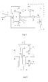
- Fig.4 is the circuit structure of the embodiment in the fig.3 ;
- Fig.5 is the circuit frame of the control circuit board of the embodiment in the fig.3 ;
- Fig.6 is the working flow chart of the embodiment in the fig.3 .
- the structure of the first embodiment in the present invention of a steam station which can remove the calcareous water scale is figured in the fig.2 .
- the housing 2 of the steam station is disposed with a water tank 3, a pump4, a boiler 5, a three-way solenoid valve 6, a power switch 7 and a removing switch 8.
- the outlet of the water tank 3 is connected to the inlet of the pump 4 by the first pipe 21.
- the outlet of the pump 4 is connected to the inlet of the boiler 5 by the second pipe 22.
- the steam outlet of the boiler 5 is connected to the inlet of the three-way solenoid valve by the third pipe 23.
- the first outlet of the three-way solenoid valve 6 is connected to the steam pipe 24, the leading-out end of which is connected to the external iron 1.
- the second outlet of the three-way solenoid valve 6 is connected to the water pipe 25, the leading-out end of which is connected to the external container 10.
- the power switch 7 is disposed to control the power supply of the pump 4 and the heating pan.
- the three-way solenoid valve 6 is switched over between a first status when the inlet is connected to the first outlet and a second status when the inlet is connected to second outlet under the control of the removing switch 8.
- the water is injected into the water tank 3. Then the power switch 7 is switched on but the removing switch is not.
- the three-way solenoid valve 6 is situated in the first status when the inlet is connected to the first outlet.
- the pump 4 and the heating pan of the boiler 5 are powered by the AC power; the water in the water tank 3 extracted to the boiler by the pump 4 is heated by the heating pan to make wet steam, which is transported to the external iron 1 to iron the cloth through the steam outlet, the first outlet of the three-way solenoid valve 6 and the steam pipe 24.
- the cleaning solution is injected to the water tank 3. Then the power switch 7 and the removing switch 8 are powered on.
- the three-way solenoid valve is switched over to the second status when the inlet is connected to the second outlet.
- the pump 4 and the heating pan of the boiler 5 are powered by the AC power.
- the cleaning solution in the water tank 3 extracted to the boiler by the pump 4 is heated by the heating pan.
- the cleaning solution heated with the dissolved calcareous water scale is extracted out to the container 10 through the second outlet of the three-way solenoid valve 6 and the water pipe 25.
- the structure of the second embodiment in the present invention of a steam station which can remove the calcareous water scale is figured in the fig.3 .
- the housing 2 of the steam station is disposed with a water tank 3, a pump 4, a boiler 5, a three-way solenoid valve 6, a power switch 7, a removing switch 8 and a control circuit board 9.
- the outlet of the water tank 3 is connected to the inlet of the pump 4 by the first pipe 21.
- the outlet of the pump 4 is connected to the inlet of the boiler 5 by the second pipe 22.
- the steam outlet of the boiler 5 is connected to the inlet of the three-way solenoid valve 6 by the third pipe 23.
- the first outlet of the three-way solenoid valve is connected to the steam pipe 24, the leading-out end of which is connected to the external iron 1.
- the second outlet of the three-way solenoid valve is connected to the water pipe 25, the leading-out end of which is connected to the external container 10.
- the boiler 5 is equipped with a heating pan 51, a first thermostat 52, a second thermostat 53 and a thermal fuse 54, which are series connected. Thereinto, the temperature control value of the first thermostat is 220°C, and that of the second one is 100°C.
- two input ports of the power switch are connected to the firing line L and the zero line N of the AC power separately.
- the output port of the firing line of the power switch 7 is connected to the input port 91 of the firing line of the AC power on the control circuit board 9, the firing line of the pump 4, the firing line port of the three-way solenoid valve 6 and the free end of the second thermostat 53 of the boiler 5.
- the output port of the zero line of the power switch 7 is connected to the input port 92 of the zero line of the AC power on the control circuit board 9 and the free end of the heating pan 51 of the boiler 5.
- the cleaning controlling ports 93, 94 of the control circuit board 9 are connected to the both ends of the removing switch 8 separately.
- the pump controlling input port 90 on the control circuit board 9 is connected to the external iron 1 to activate the sensor 12.
- the first output port 95 of the control circuit board 9 is connected to the zero line of the pump 4 to control it.
- the second output port 96 of the control circuit board 9 is connected to the joint of the first thermostat 52 and the second thermostat 53 to control heating pan to control the temperature of the boiler by the heating pan 51 made from the first thermostat 52 and the second thermostat 53.
- the third output port 97 of the control circuit board 9 is connected to the zero line of the three-way solenoid 6 to control the switchover of the three-way solenoid 6.
- the water is injected to the water tank 3. And then the power switch 7 is switched on to supply power to the input ports 91, 92 of the AC power on the control circuit board 9 while the removing switch is switched off.
- the removing switch 8 does not transfer control information to the cleaning controlling port 93, 94 on the control circuit board 9.
- the second output port 96 on the control circuit board 9 is connected to the firing line L of the AC power. Both ends of the second thermostat 53 are connected to the firing line L of the AC power separately, so the second thermostat 53 does not work.
- the boiler 5 is heated to work in a temperature of 220°C by the heating pan 51 made from the first thermostat under the control of the second output port 96 on the control circuit board 9.
- the first output port 95 on the control circuit board 9 is connected to the zero line N of the AC power, and the pump 4 is powered on.
- the water in the water tank 3 pumped to the boiler 5 is heated by the heating pan 51 to make wet steam.
- the third output port 97 on the control circuit board 9 is disconnected to the AC power. So the three-way solenoid valve powered off is situated in the first status when the inlet is connected to the first outlet.
- the wet steam is transported to the external iron 1 for ironing the cloth through the steam outlet of the boiler 5, the first outlet of the three-way solenoid valve 6 and the steam pipe 24.
- the cleaning solution is injected to the water tank 3.
- the power switch 7 is switched on to supply power to the input ports 91, 92 of the AC power on the control circuit board 9; the removing switch 8 is switched on, and the removing control port 93, 94 of the control circuit board 9is received the control information from the removing switch 8.
- the second output 96 on the control circuit board 9 is disconnected from the firing line L of the AC power.
- the second thermostat 53 works.
- the temperature control value of the second thermostat is 100°C, which is lower than that of the first one with 220°C. When the temperature of the boiler 5 reaches to 100°C, the second thermostat 53 turns to the cut-off status and the heating pan 51 is powered off.
- the boiler 5 is heated in a temperature of 100°C by the heating pan 51 made from the second thermostat under the control of the second output port 96 of the control circuit board.
- the first output port 95 on the control circuit board 9 is connected to the zero line N of the AC power, and the pump 4 is powered on.
- the cleaning solution in the box 3 is pumped to the boiler 5 by the pump 4 and heated by the heating pan 51.
- the calcareous water scale is dissolved with the heated cleaning solution.
- the third output port 97 on the control circuit board 9 is connected to the AC power.
- the three-way solenoid valve 6 is powered on and situated in the second status when the inlet is connected to the second outlet.
- the cleaning solution in the boiler is extracted out to the container 10 with the dissolved calcareous water scale through the second outlet of the three-way solenoid valve and the pipe 25.
- the control circuit board 9 applied is figured as the fig.5 .
- the control circuit board 9 is equipped with a controller 991, a power detector 992, a first switch 993, a second switch 994 and a third switch 995.
- the controller 991 is adopted with a programmable control unit or a microprocessor.
- the power detector 992 is adopted with a step-down/rectification combination circuit consisting of divider resistance and diode.
- the first switch 993, the second switch 994 and the third switch 995 can be adopted with some kind of switch device such as a relay or bidirectional triode thyristor.
- the zero line input port 92 of the AC power on the control circuit board 9 is connected to the input of the first switch 993.
- the firing line input port of the AC power on the control circuit board 9 is connected to the input of the power detector 992, the input of the second switch 994 and the input of the third switch 995.
- One of the inputs of the controller 991 is serviced as the pump control input port 90 to receive the activating signal from the activating sensor 12 of the external iron1.
- the power on signal is transmitted to the controller 991 from the power detector 992.
- the removing signal is transmitted to the controller 991 from the removing control port 93, 94.
- the first control output port of the controller is connected to the control input port of the first switch 993;
- the second control output port of the controller 991 is connected to the control input port of the second switch 994;
- the third control output port of the controller 991 is connected to the control input port of the third switch 995; the three switches are controlled by the three control output port of the controller 991 separately.
- the output of the first switch 993 is the first output port 95 on the control circuit board 9
- the output of the second switch 994 is the second output port 96 on the control circuit board 9
- the output of the third switch 995 is the third output port 97 on the control circuit board 9.
- the controlling method of this embodiment applying the control circuit board 8 is figured as in the fig.6 .
- Step 100 the controller 991 is received with the power-on signal transmitted from the power detector 992, make sure that the power switch 7 is shut down, and then go to the step 101.
- Step 101 the controller 991 detects that whether the controlling information is transported from the removing switch 8 to the cleaning controlling port 93, 94 on the control circuit board 9. That is whether the button of the removing switch 8 is pushed down and switched on. If is, go to the step 103 to remove the calcareous water scale; if not, go to the step 111 to generate the wet steam.
- Step 111 the gate signal to breakover the second switch 994 is transmitted to the control input port of the second switch 994 from the second control output port of the controller 991.
- the output of the second switch 994 as the second output port 96 of the control circuit board 9 is connected to the firing line L of the AC power.
- the second thermostat 53 doesn't work.
- the boiler is heated to work at the temperature of the 220°C by the heating pan 51 made from the first thermostat 52 under the control of the second output port 96 of the control circuit board 9. Then go to the step 112.
- Step 112 the controller 991 detects that whether the activating signal is transmitted to the activating sensor 12 of the external iron 1 from the pump control input port 90 of the control circuit board 9. That is whether the activating button 11 of the iron 1 is pushed down to activate the sensor 12. If is, go to the step 113 to make the wet steam; if not, go to the step 111 to pre-heat the boiler and wait for the activating button 11 to be pushed down.
- Step 113 the gate signal to breakover the first switch 993 is transmitted to the control input port of the first switch 993 from the first control output port of the controller 991.
- the first control output port of the controller 991 as the first output port 96 of the control circuit board 9 is connected to the zero line N of the AC power to power on the pump.
- the water in the water tank 3 is pumped by the pump 4 to be heated to make wet steam in the boiler by the heating pan 51.
- the third output port 97 of the control circuit board is disconnected from the AC power, and the three-way solenoid valve is powered off and situated in the first status when the inlet is connected to the first outlet.
- the wet steam is transported to the external iron 1 through the steam outlet of the boiler, the first outlet of the three-way solenoid valve 6 and the steam pipe 24. Go to the step 120 after the power switch 7 is shut down.
- Step 102 there is not gate signal transmitted to the control input port of the second switch 994 from the second control output port of the controller, so the second switch 994 is shut down.
- the second output port 96 of the control circuit board 9 is disconnected from the firing line L of the AC power.
- the second thermostat works. As the temperature control value of the second thermostat 53 is 100°C, which is far lower than that of the first one with 220°C, the second thermostat 53 is cut off and the heating pan 51 is powered off when the temperature of the boiler reaches to 100°C.
- the boiler is heated to work at the temperature of 100°C by the heating pan 51 made from the second thermostat under the control of the second output port 96 on the control circuit board 9. Then go to the step 103.
- Step 103 the gate signal to breakover the first switch 993 is transmitted to the control input port of the first switch 993 from the first control output port of the controller 991.
- the output port of the first switch 993 as the first output port 95 of the control circuit board 9 is connected to the zero line N of the AC power to power on the pump.
- the cleaning solution in the water tank 3 is pumped to the boiler 5 heated by the heating pan 51.
- the calcareous water scale in the boiler 5 is dissolved by the heated cleaning solution.
- the gate signal to breakover the third switch 995 is transmitted to the control input port of the third switch 995 from the third control output port of the controller 991.
- the output port of the third switch 995 as the third output port 97 of the control circuit board 9 is connected to the zero line N of the AC power to power on the three-way solenoid valve, which is situated to the second status when the inlet is connected to the second outlet.
- the cleaning solution in the boiler 5 is extracted out to the container 10 through the second outlet of the three-way solenoid valve 6 and the water pipe 25 with the dissolved calcareous water scale. Then go to the step 104.
- Step 104 a ten seconds gate signal to breakover the first switch 993 for ten seconds is transmitted to the control input port of the first switch 993 from the first control output port of the controller 991.
- the output port of the first switch 993 as the first output port 95 of the control circuit board 9 is connected to the zero line N of the AC power for ten seconds.
- the pump is powered on for ten seconds.
- the cleaning solution in the water tank 3 is pumped by the pump 4 to be heated for ten seconds.
- the calcareous water scale in the boiler 5 is dissolved by the heated cleaning solution.
- the gate signal is cut off for fifteen seconds to the control input port of the first switch 993 from the first control output port of the controller 991, making the first switch 993 shut down for fifteen seconds.
- the output of the first switch 993 as the first output port of the control circuit board 9 is disconnected from the zero line N of the AC power for fifteen seconds.
- the pump 4 is powered off for fifteen seconds.
- the cleaning solution in the water tank 3 is stopped to be pumped to the boiler 5 by the pump 4 and heated by the heating pan 51 for fifteen seconds.
- the pump 4 is controlled to work for ten cycles by the controller 991, and then go to the step 105.
- Step 105 the first control output port of the controller 991 stops to transmit the gate signal to the first switch 993 for three minutes, making the first switch shut down for three minutes.
- the output of the first switch 993 as the first output port of the control circuit board 9 is disconnected from the zero line N of the AC power for three minutes.
- the pump 4 is powered off for three minutes.
- the pump 4 stops to pump the cleaning solution in the water tank 3 to the boiler 5 to heat the cleaning solution by the heating pan 51 for three minutes. Then go to the step 106.
- Step 106 a ten seconds gate signal to breakover the first switch 993 for ten seconds is transmitted to the control input port of the first switch 993 from the first control output port of the controller 991.
- the output port of the first switch 993 as the first output port 95 of the control circuit board 9 is connected to the zero line N of the AC power for ten seconds.
- the pump is powered on for ten seconds.
- the cleaning solution in the water tank 3 is pumped by the pump 4 to be heated for ten seconds.
- the calcareous water scale in the boiler 5 is dissolved by the heated cleaning solution.
- the gate signal is cut off for fifteen seconds to the control input port of the first switch 993 from the first control output port of the controller 991, making the first switch 993 shut down for fifteen seconds.
- the output of the first switch 993 as the first output port of the control circuit board 9 is disconnected from the zero line N of the AC power for fifteen seconds.
- the pump 4 is powered off for fifteen seconds.
- the cleaning solution in the water tank 3 is stopped to be pumped to the boiler 5 by the pump 4 and heated by the heating pan 51 for fifteen seconds.
- the pump 4 is controlled to work for ten cycles by the controller 991, and then go to the step 107.
- Step 107 the gate signal to breakover the first switch 993 is transmitted to the control input port of the first switch 993 from the first control output port of the controller 991.
- the output port of the first switch 993 as the first output port 95 of the control circuit board 9 is connected to the zero line N of the AC power to power on the pump.
- the cleaning solution in the water tank 3 is pumped to the boiler 5 heated by the heating pan 51.
- the calcareous water scale in the boiler 5 is dissolved by the heated cleaning solution.
- the gate signal to breakover the third switch 995 is transmitted to the control input port of the third switch 995 from the third control output port of the controller 991.
- the output port of the third switch 995 as the third output port 97 of the control circuit board 9 is connected to the firing line L of the AC power to power on the three-way solenoid valve, which is situated to the second status when the inlet is connected to the second outlet.
- the cleaning solution in the boiler 5 is extracted out to the container 10 through the second outlet of the three-way solenoid valve 6 and the water pipe 25 with the dissolved calcareous water scale.
- the gate signal is transmitted to the control input of the second switch 994 from the second control output port of the controller 991 for one minute to breakover the second switch for one minute.
- the output of the second switch 994 as the second output port 96 of the control circuit board 9 is connected to the firing line L of the AC power for one minute.
- the boiler 5 is heated for one minute at a temperature of 220°C by the heating pan 51 made from the first thermostat 52 under the control of the second output port 96. Then go to the step 120.
- Step 120 the end.
- the calcareous water scale removing step is adopted with an alternation mode of dissolving, washing and drying. Then dissolve and wash the remaining calcareous water scale in the boiler in a high temperature. The effect of removing is well, the cleaning solution is saved, besides, it shortens the removing working hours.
- the present invention of a steam station which can remove the calcareous water scale is equipped with a three-way solenoid valve to switch the draw-off from the boiler. It can supply wet steam for the external iron, and remove the calcareous water scale by heating the cleaning solution in the boiler as well.
- the present invention is provided with well industrial applicability.
Landscapes
- Engineering & Computer Science (AREA)
- Textile Engineering (AREA)
- Health & Medical Sciences (AREA)
- Public Health (AREA)
- Irons (AREA)
- Cleaning By Liquid Or Steam (AREA)
Applications Claiming Priority (2)
| Application Number | Priority Date | Filing Date | Title |
|---|---|---|---|
| CN2009101113701A CN101839468B (zh) | 2009-03-19 | 2009-03-19 | 可去除钙质水垢的蒸汽站 |
| PCT/CN2010/070871 WO2010105524A1 (fr) | 2009-03-19 | 2010-03-04 | Centrale vapeur éliminant le tartre de calcaire |
Publications (1)
| Publication Number | Publication Date |
|---|---|
| EP2410088A1 true EP2410088A1 (fr) | 2012-01-25 |
Family
ID=42739181
Family Applications (1)
| Application Number | Title | Priority Date | Filing Date |
|---|---|---|---|
| EP10753091A Withdrawn EP2410088A1 (fr) | 2009-03-19 | 2010-03-04 | Centrale vapeur éliminant le tartre de calcaire |
Country Status (3)
| Country | Link |
|---|---|
| EP (1) | EP2410088A1 (fr) |
| CN (1) | CN101839468B (fr) |
| WO (1) | WO2010105524A1 (fr) |
Cited By (4)
| Publication number | Priority date | Publication date | Assignee | Title |
|---|---|---|---|---|
| EP2942430A1 (fr) * | 2014-05-06 | 2015-11-11 | Seb S.A. | Procede de fonctionnement d'un appareil de repassage comportant une cuve pour la generation de vapeur sous pression |
| EP2942431A1 (fr) * | 2014-05-06 | 2015-11-11 | Seb S.A. | Procédé de fonctionnement d'un appareil de repassage comportant une cuve pour la génération de vapeur sous pression |
| IT201900015201A1 (it) * | 2019-08-29 | 2021-03-01 | De Longhi Appliances Srl | Base di supporto per un apparato stirante |
| US11618992B2 (en) | 2017-06-16 | 2023-04-04 | Spectrum Brands, Inc. | Steam generator with pre-heat chamber and filter |
Families Citing this family (3)
| Publication number | Priority date | Publication date | Assignee | Title |
|---|---|---|---|---|
| CN103015144A (zh) * | 2012-12-11 | 2013-04-03 | 广东新宝电器股份有限公司 | 蒸汽站电熨斗 |
| IT201700104917A1 (it) * | 2017-09-20 | 2019-03-20 | De Longhi Appliances Srl | Caldaia |
| KR102793625B1 (ko) | 2019-12-11 | 2025-04-11 | 삼성전자주식회사 | 의류관리장치 및 그 제어방법 |
Family Cites Families (4)
| Publication number | Priority date | Publication date | Assignee | Title |
|---|---|---|---|---|
| ES2198832T3 (es) * | 1998-11-04 | 2004-02-01 | Esse 85 S.R.L. | Plancha a vapor del tipo profesional. |
| EP1678368A1 (fr) * | 2003-09-12 | 2006-07-12 | Nemox S.p.A | Fer a repasser |
| JP5053272B2 (ja) * | 2005-07-11 | 2012-10-17 | コーニンクレッカ フィリップス エレクトロニクス エヌ ヴィ | 蒸気装置との使用のためのボイラシステムを洗浄するための方法 |
| CN201056648Y (zh) * | 2007-01-19 | 2008-05-07 | 宁波夏纳电器有限公司 | 电热膜蒸汽发生器式蒸汽电熨斗 |
-
2009
- 2009-03-19 CN CN2009101113701A patent/CN101839468B/zh not_active Expired - Fee Related
-
2010
- 2010-03-04 EP EP10753091A patent/EP2410088A1/fr not_active Withdrawn
- 2010-03-04 WO PCT/CN2010/070871 patent/WO2010105524A1/fr not_active Ceased
Non-Patent Citations (1)
| Title |
|---|
| See references of WO2010105524A1 * |
Cited By (6)
| Publication number | Priority date | Publication date | Assignee | Title |
|---|---|---|---|---|
| EP2942430A1 (fr) * | 2014-05-06 | 2015-11-11 | Seb S.A. | Procede de fonctionnement d'un appareil de repassage comportant une cuve pour la generation de vapeur sous pression |
| EP2942431A1 (fr) * | 2014-05-06 | 2015-11-11 | Seb S.A. | Procédé de fonctionnement d'un appareil de repassage comportant une cuve pour la génération de vapeur sous pression |
| FR3020818A1 (fr) * | 2014-05-06 | 2015-11-13 | Seb Sa | Procede de fonctionnement d'un appareil de repassage comportant une cuve pour la generation de vapeur sous pression |
| FR3020817A1 (fr) * | 2014-05-06 | 2015-11-13 | Seb Sa | Procede de fonctionnement d'un appareil de repassage comportant une cuve pour la generation de vapeur sous pression |
| US11618992B2 (en) | 2017-06-16 | 2023-04-04 | Spectrum Brands, Inc. | Steam generator with pre-heat chamber and filter |
| IT201900015201A1 (it) * | 2019-08-29 | 2021-03-01 | De Longhi Appliances Srl | Base di supporto per un apparato stirante |
Also Published As
| Publication number | Publication date |
|---|---|
| WO2010105524A1 (fr) | 2010-09-23 |
| CN101839468A (zh) | 2010-09-22 |
| CN101839468B (zh) | 2012-07-25 |
Similar Documents
| Publication | Publication Date | Title |
|---|---|---|
| CN101726091B (zh) | 一种快速将水加热至沸腾的电加热装置及其加热方法 | |
| CN101839468B (zh) | 可去除钙质水垢的蒸汽站 | |
| JP6111619B2 (ja) | 浴槽洗浄装置 | |
| CN104848550A (zh) | 电热水器 | |
| CN105299725A (zh) | 烟机及其供水系统和控制方法 | |
| CN107034631B (zh) | 一种洗衣机及其控制方法 | |
| CN104764188B (zh) | 热水器及其加热控制方法 | |
| US10154754B2 (en) | Apparatus and method for managing water levels in a boiler of a coffee machine | |
| CN103015144A (zh) | 蒸汽站电熨斗 | |
| JP2017198379A (ja) | 風呂給湯装置 | |
| AU2014335804A1 (en) | Apparatus and method for managing water levels in a boiler of a coffee machine | |
| KR100809476B1 (ko) | 비데 및 비데용 순간온수모듈 제어방법 | |
| CN109706717B (zh) | 一种可切换熨烫模式的熨烫装置 | |
| CN107386397A (zh) | 一种用于医疗护理床的智能冲洗装置 | |
| JP5903540B2 (ja) | 給湯装置 | |
| JP2016191485A (ja) | 貯湯式給湯装置 | |
| CN104665572B (zh) | 蒸汽烹饪设备及其控制方法 | |
| JP2012247130A (ja) | 貯湯式給湯機 | |
| CN201983420U (zh) | 中央热水循环系统即热式电热水器 | |
| CN204574526U (zh) | 一种节能型热交换器水泵延时自动关闭控制装置 | |
| CN201229050Y (zh) | 一种全自动恒温式电热水器 | |
| CN208124421U (zh) | 向多个终端供应温开水的系统 | |
| CN110953626A (zh) | 一种隐藏式烟机热水器联动控制方式及结构 | |
| JP3021237B2 (ja) | 食器洗浄機を含む複数端末に対して一台の給湯機を用いて給湯するための制御装置 | |
| CN104807198A (zh) | 一种节能型热交换器水泵延时自动关闭控制装置 |
Legal Events
| Date | Code | Title | Description |
|---|---|---|---|
| PUAI | Public reference made under article 153(3) epc to a published international application that has entered the european phase |
Free format text: ORIGINAL CODE: 0009012 |
|
| 17P | Request for examination filed |
Effective date: 20111019 |
|
| AK | Designated contracting states |
Kind code of ref document: A1 Designated state(s): AT BE BG CH CY CZ DE DK EE ES FI FR GB GR HR HU IE IS IT LI LT LU LV MC MK MT NL NO PL PT RO SE SI SK SM TR |
|
| DAX | Request for extension of the european patent (deleted) | ||
| STAA | Information on the status of an ep patent application or granted ep patent |
Free format text: STATUS: THE APPLICATION HAS BEEN WITHDRAWN |
|
| 18W | Application withdrawn |
Effective date: 20151106 |