EP2410171A1 - Éolienne dotée d'un rotor avec moyeu - Google Patents
Éolienne dotée d'un rotor avec moyeu Download PDFInfo
- Publication number
- EP2410171A1 EP2410171A1 EP10170630A EP10170630A EP2410171A1 EP 2410171 A1 EP2410171 A1 EP 2410171A1 EP 10170630 A EP10170630 A EP 10170630A EP 10170630 A EP10170630 A EP 10170630A EP 2410171 A1 EP2410171 A1 EP 2410171A1
- Authority
- EP
- European Patent Office
- Prior art keywords
- rotor
- wind turbine
- rotor blade
- flow surface
- turbine according
- Prior art date
- Legal status (The legal status is an assumption and is not a legal conclusion. Google has not performed a legal analysis and makes no representation as to the accuracy of the status listed.)
- Withdrawn
Links
Images


Classifications
-
- F—MECHANICAL ENGINEERING; LIGHTING; HEATING; WEAPONS; BLASTING
- F03—MACHINES OR ENGINES FOR LIQUIDS; WIND, SPRING, OR WEIGHT MOTORS; PRODUCING MECHANICAL POWER OR A REACTIVE PROPULSIVE THRUST, NOT OTHERWISE PROVIDED FOR
- F03D—WIND MOTORS
- F03D1/00—Wind motors with rotation axis substantially parallel to the air flow entering the rotor
- F03D1/06—Rotors
- F03D1/0608—Rotors characterised by their aerodynamic shape
-
- F—MECHANICAL ENGINEERING; LIGHTING; HEATING; WEAPONS; BLASTING
- F05—INDEXING SCHEMES RELATING TO ENGINES OR PUMPS IN VARIOUS SUBCLASSES OF CLASSES F01-F04
- F05B—INDEXING SCHEME RELATING TO WIND, SPRING, WEIGHT, INERTIA OR LIKE MOTORS, TO MACHINES OR ENGINES FOR LIQUIDS COVERED BY SUBCLASSES F03B, F03D AND F03G
- F05B2240/00—Components
- F05B2240/10—Stators
- F05B2240/13—Stators to collect or cause flow towards or away from turbines
-
- Y—GENERAL TAGGING OF NEW TECHNOLOGICAL DEVELOPMENTS; GENERAL TAGGING OF CROSS-SECTIONAL TECHNOLOGIES SPANNING OVER SEVERAL SECTIONS OF THE IPC; TECHNICAL SUBJECTS COVERED BY FORMER USPC CROSS-REFERENCE ART COLLECTIONS [XRACs] AND DIGESTS
- Y02—TECHNOLOGIES OR APPLICATIONS FOR MITIGATION OR ADAPTATION AGAINST CLIMATE CHANGE
- Y02E—REDUCTION OF GREENHOUSE GAS [GHG] EMISSIONS, RELATED TO ENERGY GENERATION, TRANSMISSION OR DISTRIBUTION
- Y02E10/00—Energy generation through renewable energy sources
- Y02E10/70—Wind energy
- Y02E10/72—Wind turbines with rotation axis in wind direction
Definitions
- the present invention relates to a wind turbine comprising a rotor having at least two radially extending rotor blades, and a hub positioned at the center of the at least two radially extending rotor blades.
- the present invention seeks to provide an improvement in efficiency of a rotor blade construction of a wind turbine.
- a wind turbine according to the preamble defined above, wherein the wind turbine further comprises a flow surface for each rotor blade of the wind turbine rotor attached to the hub, each flow surface being arranged to direct flow of air from a center part of the rotor towards an associated rotor blade, and each flow surface extending in a radial direction beyond a root attachment of the associated rotor blade.
- the combination of flow surfaces forms a set of skirts, which cover a center part of the rotor surface (i.e. ⁇ r 2 where r is the rotor radius).
- each flow surface overlaps at least part of the wing shape of the rotor blade.
- rotor blades of wind turbines have a wing shape along a large part of the rotor blade, but this transitions into a circular shape near the rotor hub, in order to allow attachment of the rotor blade to the hub, and to allow a pitching mechanism in the rotor hub to connect to each rotor blade.
- each flow surface extends in a radial direction over a distance which is equal to or greater than 1% of a rotor blade length.
- the rotor blade length is somewhat smaller than the radius of the wind turbine rotor, as a result of the attachment of the rotor blades to the hub.
- the present invention embodiments are e.g. applied in direct drive wind turbines, wherein the hub is attached to a rotor part of a direct drive wind turbine generator. As the rotor part of the generator is in general larger for direct drive wind turbines, attachment of the flow surfaces is easier to accomplish.
- each flow surface is attached to the rotor part using a stub element attached to an outer section of the rotor part.
- the larger diameter of the rotor part allows to provide a strong and efficient structure for attaching the flow surfaces to the hub of the wind turbine.
- Each flow surface is moveably connected to the associated rotor blade in a further embodiment. This allows normal pitching of the rotor blade, and keeps the flow surfaces correctly positioned to work effectively.
- Each flow surface is e.g. connected to the associated rotor blade using a sliding mechanism, which keeps the outer part of the flow surface at a fixed distance from the rotor blade.
- each flow surface is connected to the associated rotor blade using a roller mechanism. This embodiment would allow a more easy pitching motion of the rotor blade with respect to the stationary position of the flow surface.
- each flow surface is connected to the associated rotor blade using a magnetic bearing mechanism, e.g.
- each flow surface is connected to the associated rotor blade using a flexible construction attached to the rotor blade.
- a material is used for the flow surfaces with sufficient flexibility in order to allow pitching operation of the associated rotor blade during operation. This would reduce the (frontal) surface area of the flow surface when moving the rotor blades towards vane position and consequently reduce loads resulting from high wind speeds.
- each flow surface is a curved surface.
- the curved surface is adapted to be effective at a nominal rotor speed, in order to provide an efficiency increase of the wind turbine at nominal operating conditions.
- each flow surface extends the effective cord length of the rotor blade near the root of the rotor blade, thus aiding in using more of the wind energy for transformation into rotation of the wind turbine rotor (and hence producing more electrical energy).
- Each flow surface is made of a material having a predetermined degree of flexibility in a further embodiment.
- the flexing of the flow surface allows the wind turbine to better withstand gusts of wind.
- the flexibility of the flow surface may aid in guiding the wind efficiently depending on wind force.
- each flow surface is a rotor blade shaped surface having a radius shorter than the radius of the rotor, wherein each rotor blade shaped surface is positioned in between rotor blades.
- This double rotor blade design is another form of improvement to existing wind turbine rotor designs which increases efficiency of the wind turbine.
- each rotor blade shaped surface is attached to the hub using a secondary pitching mechanism. The pitch capability of the additional blades (flow surfaces) allows to position these in the most efficient manner depending on the actual operational parameters of the wind turbine.
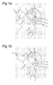
- Fig. 1 a part of a wind turbine is shown in a perspective view of a first embodiment of the present invention.
- Fig. 1a show a perspective view of the wind turbine where the rotor blades 2 are in feathering position, and Fig. 1b the same perspective view when the rotor blades 2 are pitched to an operational position.
- Fig. 1c shows a frontal view of the wind turbine, where a part of one of the flow surfaces 4 (see description below) is drawn in phantom lines.
- the rotor 1 of the wind turbine comprises at least two rotor blades 2, which extend in a radial direction of the rotor 1. In the embodiment shown three rotor blades 2 are provided.
- the rotor blades 2 are attached to a rotor hub 6 at a root attachment 5 of each rotor blade 2.
- the attachment at the root location 5 allows to pitch the rotor blades 2 depending on operational parameters of the wind turbine.
- the attachment at the root location 5 usually also means that the blade shape of the rotor blade cannot be extended all the way up to the root attachment 5 (see Fig. 1c ).
- a hub 3 or nose wing is provided at the center of the at least two radially extending rotor blades 2.
- the hub 3 comprises as many flow surfaces 4 as rotor blades 2 are present, in the embodiment shown three flow surfaces 4.
- the flow surfaces 4 are connected to each other to form an assembly of skirt like surfaces, which in operation provides a single assembly which captures wind in a limited radius around the rotor center.
- each flow surface 4 is arranged to direct flow of air from a center part of the rotor towards the associated rotor blade 2.
- Each flow surface 4 extends in a radial direction beyond the root attachment 5 of the rotor blade 2 to the rotor hub 6.
- the set of flow surfaces 4 thus covers at least a minimal a center part of the rotor surface (i.e. a part of ⁇ r 2 m 2 , r being the radius of the rotor 1).
- each flow surface 4 overlaps at least part of the wing shape of the associated rotor blade 2, i.e. well beyond the root attachment 5 seen in an axial direction of the rotor 1.
- the root attachment 5 of present day wind turbines may be fitted with covers which protect the rotating elements of the pitch mechanism of a rotor blade.
- Such covers in general are fitted around the entire root attachment 5 in order to prevent ingress of water and dirt, and are in no way designed to direct air flow from the center part of the rotor surface towards the rotor blades, for which effect the present embodiments of the flow surfaces 4 are designed.
- each flow surface 4 extends in a radial direction over a distance which is equal to or greater than 1% of a rotor blade length (the rotor blade length being defined as the longest dimension of the rotor blade 2 measured from the root attachment 5, i.e. somewhat smaller than the radius of wind turbine rotor 1). This effectively covers the region of the rotor blade 2 from the center to beyond the root attachment 5, and thus provides additional capability to catch wind energy and convert this energy into motion of the rotor 1.
- Each flow surface 4 is a curved surface, in which the curvature is determined to provide an aerodynamically suitable surface, which forms a combination of effective surface for converting wind energy into rotor motion, and guidance of the air flow towards the more aerodynamically efficient parts of each rotor blade 2.
- the surface is adapted to be effective at a nominal rotor speed range of the wind turbine as a whole. This provides the additional advantage that energy conversion efficiency is improved in a wind speed range which is mostly available in operation.
- the shape of the flow surface 4 can be adapted to extend the effective cord length l c of the rotor blade 2 near the root of the rotor blade 2 in further embodiments (see Fig. 1c ). This further extends the efficiency of energy conversion of the wind turbine.
- the hub 3 with the flow surfaces 4 is attached to a hub 6 of the rotor 1, or more in general to an element of the wind turbine fixedly connected to an axis of the rotor 1.
- the attachment can be made using various attachment mechanisms, e.g. using stubs or other light weight attachment assemblies.
- advantage can be taken of structural features of certain types of wind turbines, in this case of direct driven wind turbines.
- the hub 3 is attached to a rotor part 11 of a direct drive wind turbine generator.
- each flow surface 4 is attached to the rotor part 11 using a stub element 9 attached to an outer section of the rotor part (seen in radial direction of the rotor 1), as shown in the perspective vies of Fig. 1a-b and Fig. 2a-c ). This allows to provide as much constructional stiffness as possible when connecting the flow surfaces 4 to the hub 3 of the wind turbine.
- each flow surface 4 of the present invention embodiments are also supported at their remote end using a moveable connection to the associated rotor blade 2, to allow the pitching motion of the rotor blade 2.
- each flow surface is connected to rotor blade using a sliding mechanism 7, as shown in general in Fig. 1 .
- this embodiment provides sufficient strength to keep the flow surfaces 4 in position for proper operation, while still allowing the rotor blades 2 to pitch.
- each flow surface is connected to an associated rotor blade 2 using a roller mechanism 8. This would allow to obtain less friction between the attachment structure of the flow surface 4 and the surface of rotor blade 2.
- each flow surface 4 is connected to the associated rotor blade 2 using a magnetic bearing mechanism, comprising e.g. magnets on the flow surfaces, and a steel strip on the rotor blade 2.
- the flow surfaces 4 are made from a material having a predetermined degree of flexibility. When winds are very strong, or gusty, this will effectively decrease the wind catching surface of the flow surfaces 4, as the wind is able to bend away the flow surface 4 as a result of which a less efficient surface is provided.
- the material can be any usual material used for making rotor blades, including metal, carbon fiber or glass fiber based materials. The actual shape and thickness of the material used may then provide the desired degree of flexibility.
- a further group of embodiments comprises the feature that each flow surface 4 is connected to the associated rotor blade 2 using a flexible construction attached to the rotor blade 2.
- the flow surfaces 4 are also attached in a fixed manner to the hub 3.
- a material for the flow surfaces 4 a material is used with sufficient flexibility in order to allow pitching operation of the associated rotor blade 2 during operation.
- the flexible construction allows movement or shape change of the flow surface, and is e.g. a point attachment on the frontal wing part of the associated rotor blade 2.
- the flow surface 4 is stretched in this embodiment as a sail, and when the rotor blade 2 pitches to a vane position, the flow surface 4 is loosened. This would reduce the (frontal) surface area of the flow surface 4 when moving the rotor blades 2 towards vane position and consequently reduce loads resulting from high wind speeds.
- An even further group of embodiments uses a slightly different structure to better and more efficiently use as much as possible wind catching surface of the rotor 1, by providing a hub 3 with flow surfaces 4 as part of the rotor 1, wherein each flow surface 4 is a rotor blade shaped surface having a radius r s shorter than the radius of the rotor 1, wherein each flow surface 4 is positioned in between rotor blades 2.
- the hub 3 can be designed to effectively capture wind energy flowing at the center part of the rotor 1 wind catching surface.
- each rotor blade shaped surface 4 is attached to the hub using a secondary pitch mechanism 12. This allows the flow surfaces to be controlled in pitch, end hence in effectiveness in catching additional wind energy.
- the secondary pitch mechanism might also be fitted with additional elements (e.g. friction dampers) to allow the wind force itself to change the pitch of the rotor blade shaped surfaces 4, e.g. when gusts occur.
- additional elements e.g. friction dampers
Landscapes
- Engineering & Computer Science (AREA)
- Physics & Mathematics (AREA)
- Fluid Mechanics (AREA)
- Life Sciences & Earth Sciences (AREA)
- Sustainable Development (AREA)
- Sustainable Energy (AREA)
- Chemical & Material Sciences (AREA)
- Combustion & Propulsion (AREA)
- Mechanical Engineering (AREA)
- General Engineering & Computer Science (AREA)
- Wind Motors (AREA)
Priority Applications (3)
| Application Number | Priority Date | Filing Date | Title |
|---|---|---|---|
| EP10170630A EP2410171A1 (fr) | 2010-07-23 | 2010-07-23 | Éolienne dotée d'un rotor avec moyeu |
| PCT/NL2011/050532 WO2012011812A1 (fr) | 2010-07-23 | 2011-07-21 | Éolienne dotée d'une ailette de nez |
| EP11738072.5A EP2596236A1 (fr) | 2010-07-23 | 2011-07-21 | Éolienne dotée d'une ailette de nez |
Applications Claiming Priority (1)
| Application Number | Priority Date | Filing Date | Title |
|---|---|---|---|
| EP10170630A EP2410171A1 (fr) | 2010-07-23 | 2010-07-23 | Éolienne dotée d'un rotor avec moyeu |
Publications (1)
| Publication Number | Publication Date |
|---|---|
| EP2410171A1 true EP2410171A1 (fr) | 2012-01-25 |
Family
ID=43217081
Family Applications (2)
| Application Number | Title | Priority Date | Filing Date |
|---|---|---|---|
| EP10170630A Withdrawn EP2410171A1 (fr) | 2010-07-23 | 2010-07-23 | Éolienne dotée d'un rotor avec moyeu |
| EP11738072.5A Withdrawn EP2596236A1 (fr) | 2010-07-23 | 2011-07-21 | Éolienne dotée d'une ailette de nez |
Family Applications After (1)
| Application Number | Title | Priority Date | Filing Date |
|---|---|---|---|
| EP11738072.5A Withdrawn EP2596236A1 (fr) | 2010-07-23 | 2011-07-21 | Éolienne dotée d'une ailette de nez |
Country Status (2)
| Country | Link |
|---|---|
| EP (2) | EP2410171A1 (fr) |
| WO (1) | WO2012011812A1 (fr) |
Cited By (2)
| Publication number | Priority date | Publication date | Assignee | Title |
|---|---|---|---|---|
| EP3177838A4 (fr) * | 2014-08-05 | 2018-05-02 | Ryan Church | Structure de réorientation de fluide |
| US12078145B2 (en) | 2014-08-05 | 2024-09-03 | Biomerenewables Inc. | Fluidic turbine structure |
Families Citing this family (1)
| Publication number | Priority date | Publication date | Assignee | Title |
|---|---|---|---|---|
| RS59763B1 (sr) | 2015-11-19 | 2020-02-28 | Jiangsu Hengrui Medicine Co | Derivati benzofurana, postupci njihove pripreme i njihova upotreba u medicini |
Citations (8)
| Publication number | Priority date | Publication date | Assignee | Title |
|---|---|---|---|---|
| GB172997A (en) * | 1920-06-25 | 1921-12-28 | Alexander Albert Holle | Improvements in screw propellers and the like |
| DE483057C (de) * | 1926-01-12 | 1929-09-25 | Inst Voor Aero En Hydro Dynami | Propeller, bei dem zwischen den Hauptfluegeln kuerzere Hilfsfluegel angeordnet sind |
| NL1002324C1 (nl) * | 1996-02-13 | 1997-08-14 | Hendrikus Julianus Bouma | Rotorbladophanging van een windturbine. |
| WO2003104646A1 (fr) | 2002-06-05 | 2003-12-18 | Aloys Wobben | Pale de rotor d'une eolienne |
| US20060239821A1 (en) * | 2005-04-21 | 2006-10-26 | Mccabe Francis J | Windmill blade shaping and mounting to enhance performance |
| WO2007057021A1 (fr) * | 2005-11-21 | 2007-05-24 | L.M. Glasfiber S/A | Centrale eolienne avec jeu supplementaire d’aubes |
| DE102008037605A1 (de) * | 2007-12-06 | 2009-06-10 | General Electric Co. | Mehrteilige Rotorflügel und dieselben enthaltende Windkraftanlage |
| WO2009097850A2 (fr) * | 2008-02-05 | 2009-08-13 | Bjarne Flytklint | Rotor, en particulier pour des hélices ou des systèmes à énergie éolienne |
-
2010
- 2010-07-23 EP EP10170630A patent/EP2410171A1/fr not_active Withdrawn
-
2011
- 2011-07-21 WO PCT/NL2011/050532 patent/WO2012011812A1/fr not_active Ceased
- 2011-07-21 EP EP11738072.5A patent/EP2596236A1/fr not_active Withdrawn
Patent Citations (8)
| Publication number | Priority date | Publication date | Assignee | Title |
|---|---|---|---|---|
| GB172997A (en) * | 1920-06-25 | 1921-12-28 | Alexander Albert Holle | Improvements in screw propellers and the like |
| DE483057C (de) * | 1926-01-12 | 1929-09-25 | Inst Voor Aero En Hydro Dynami | Propeller, bei dem zwischen den Hauptfluegeln kuerzere Hilfsfluegel angeordnet sind |
| NL1002324C1 (nl) * | 1996-02-13 | 1997-08-14 | Hendrikus Julianus Bouma | Rotorbladophanging van een windturbine. |
| WO2003104646A1 (fr) | 2002-06-05 | 2003-12-18 | Aloys Wobben | Pale de rotor d'une eolienne |
| US20060239821A1 (en) * | 2005-04-21 | 2006-10-26 | Mccabe Francis J | Windmill blade shaping and mounting to enhance performance |
| WO2007057021A1 (fr) * | 2005-11-21 | 2007-05-24 | L.M. Glasfiber S/A | Centrale eolienne avec jeu supplementaire d’aubes |
| DE102008037605A1 (de) * | 2007-12-06 | 2009-06-10 | General Electric Co. | Mehrteilige Rotorflügel und dieselben enthaltende Windkraftanlage |
| WO2009097850A2 (fr) * | 2008-02-05 | 2009-08-13 | Bjarne Flytklint | Rotor, en particulier pour des hélices ou des systèmes à énergie éolienne |
Cited By (4)
| Publication number | Priority date | Publication date | Assignee | Title |
|---|---|---|---|---|
| EP3177838A4 (fr) * | 2014-08-05 | 2018-05-02 | Ryan Church | Structure de réorientation de fluide |
| US10578076B2 (en) | 2014-08-05 | 2020-03-03 | Ryan Church | Fluid-redirecting structure |
| US12078145B2 (en) | 2014-08-05 | 2024-09-03 | Biomerenewables Inc. | Fluidic turbine structure |
| US12584458B2 (en) | 2014-08-05 | 2026-03-24 | Biomerenewables Inc. | Fluidic turbine structure |
Also Published As
| Publication number | Publication date |
|---|---|
| WO2012011812A1 (fr) | 2012-01-26 |
| EP2596236A1 (fr) | 2013-05-29 |
Similar Documents
| Publication | Publication Date | Title |
|---|---|---|
| US9239040B2 (en) | Root end assembly configuration for a wind turbine rotor blade and associated forming methods | |
| KR101411057B1 (ko) | 풍력 터빈 로터 | |
| US8403642B2 (en) | Wind turbine rotor blade assembly with root curtain | |
| EP2712399B1 (fr) | Pale d'éolienne avec dispositifs permettant de réduire le bruit et procédé associé | |
| US7976283B2 (en) | Noise reducer for rotor blade in wind turbine | |
| EP2305999B1 (fr) | Des systèmes et les méthodes d'assemblage d'une extension de pale pour l'utilisation dans une éolienne | |
| EP2908002B1 (fr) | Ensemble de cloison pour pale de turbine éolienne | |
| EP2194267B1 (fr) | Manche pour le pied d'une pale d'éolienne | |
| EP2292926B1 (fr) | Pale d'éolienne à éléments hypersustentateurs | |
| US9523279B2 (en) | Rotor blade fence for a wind turbine | |
| EP2112372A1 (fr) | Éolienne à pales portées du côté sous le vent | |
| US20110142636A1 (en) | Expansion assembly for a rotor blade of a wind turbine | |
| US20120141250A1 (en) | Wind turbine shroud | |
| US20120027588A1 (en) | Root flap for rotor blade in wind turbine | |
| US20140377069A1 (en) | Pitch bearing assembly with stiffener | |
| KR102143165B1 (ko) | 풍력 발전 설비-로터 블레이드 및 이를 포함하는 풍력 발전 설비 | |
| JP5946812B2 (ja) | 風車ロータ及び風力発電装置 | |
| EP2410171A1 (fr) | Éolienne dotée d'un rotor avec moyeu | |
| US9261074B2 (en) | Variable bolt parameters for a wind turbine rotor blade | |
| CN103967700A (zh) | 鼓状可伸缩风轮以及采用该风轮的水平轴风力发电机 | |
| DK201270471A (en) | Angled blade root | |
| US20100135809A1 (en) | Wind wheel | |
| JP5918983B2 (ja) | 風力発電装置 | |
| EP2194266A1 (fr) | Agencement de rotor-stator d'une éolienne | |
| EP3085953B1 (fr) | Dôme de turbine éolienne et procédé d'assemblage |
Legal Events
| Date | Code | Title | Description |
|---|---|---|---|
| AK | Designated contracting states |
Kind code of ref document: A1 Designated state(s): AL AT BE BG CH CY CZ DE DK EE ES FI FR GB GR HR HU IE IS IT LI LT LU LV MC MK MT NL NO PL PT RO SE SI SK SM TR |
|
| AX | Request for extension of the european patent |
Extension state: BA ME RS |
|
| PUAI | Public reference made under article 153(3) epc to a published international application that has entered the european phase |
Free format text: ORIGINAL CODE: 0009012 |
|
| STAA | Information on the status of an ep patent application or granted ep patent |
Free format text: STATUS: THE APPLICATION HAS BEEN WITHDRAWN |
|
| 18W | Application withdrawn |
Effective date: 20120508 |