EP2410208A2 - Appareil de transmission de mouvement doté d'un dispositif d'élimination de jeu d'engrenage lubrifié avec de l'huile - Google Patents
Appareil de transmission de mouvement doté d'un dispositif d'élimination de jeu d'engrenage lubrifié avec de l'huile Download PDFInfo
- Publication number
- EP2410208A2 EP2410208A2 EP11174883A EP11174883A EP2410208A2 EP 2410208 A2 EP2410208 A2 EP 2410208A2 EP 11174883 A EP11174883 A EP 11174883A EP 11174883 A EP11174883 A EP 11174883A EP 2410208 A2 EP2410208 A2 EP 2410208A2
- Authority
- EP
- European Patent Office
- Prior art keywords
- driven gear
- oil
- gear
- driven
- annular flange
- Prior art date
- Legal status (The legal status is an assumption and is not a legal conclusion. Google has not performed a legal analysis and makes no representation as to the accuracy of the status listed.)
- Withdrawn
Links
- 239000010687 lubricating oil Substances 0.000 claims description 17
- 230000002093 peripheral effect Effects 0.000 claims description 6
- 230000006835 compression Effects 0.000 description 2
- 238000007906 compression Methods 0.000 description 2
- 230000001050 lubricating effect Effects 0.000 description 2
- 238000009827 uniform distribution Methods 0.000 description 1
Images

Classifications
-
- F—MECHANICAL ENGINEERING; LIGHTING; HEATING; WEAPONS; BLASTING
- F16—ENGINEERING ELEMENTS AND UNITS; GENERAL MEASURES FOR PRODUCING AND MAINTAINING EFFECTIVE FUNCTIONING OF MACHINES OR INSTALLATIONS; THERMAL INSULATION IN GENERAL
- F16H—GEARING
- F16H55/00—Elements with teeth or friction surfaces for conveying motion; Worms, pulleys or sheaves for gearing mechanisms
- F16H55/02—Toothed members; Worms
- F16H55/17—Toothed wheels
- F16H55/18—Special devices for taking up backlash
-
- F—MECHANICAL ENGINEERING; LIGHTING; HEATING; WEAPONS; BLASTING
- F16—ENGINEERING ELEMENTS AND UNITS; GENERAL MEASURES FOR PRODUCING AND MAINTAINING EFFECTIVE FUNCTIONING OF MACHINES OR INSTALLATIONS; THERMAL INSULATION IN GENERAL
- F16H—GEARING
- F16H57/00—General details of gearing
- F16H57/04—Features relating to lubrication or cooling or heating
- F16H57/042—Guidance of lubricant
- F16H57/0427—Guidance of lubricant on rotary parts, e.g. using baffles for collecting lubricant by centrifugal force
Definitions
- This invention relates to a gear clearance eliminating device, and more particularly to an oil-lubricated gear clearance eliminating device.
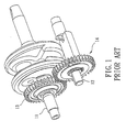
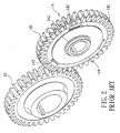
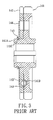
- a conventional motion transmitting apparatus includes a crankshaft 11, a balance shaft 12, a driving gear 13 sleeved fixedly on the crankshaft 11, and a driven gear unit 14 sleeved fixedly on the balance shaft 12 and meshing with the driving gear 13.
- the driven gear unit 14 includes a first driven gear 141 sleeved fixedly on the balance shaft 12 and meshing with the driving gear 13, a second driven gear 142 sleeved rotatably on an annular flange (141A) of the first driven gear 141, a plurality of coiled compression springs 143 received respectively within a plurality of grooves (141B) in a side surface of the first driven gear 141 and extending respectively into a plurality of apertures 142' in the second driven gear 142, a ring plate 144 sleeved on the flange (141A) and covering the openings 142' for confining the springs 143 between the first and second driven gears 141, 142, and a C-shaped retaining ring 145 received within an annular groove (141C) in the flange (141A) for retaining the ring plate (144) on the flange (141A).
- the first and second driven gears 141, 142 rotate relative to each other by a very small angle for eliminating clearance between the driving gear 13 and an assembly of the first and second driven gears 141, 142. Consequently, noise generated from relative rotation between the driving gear 13 and the assembly of the first and second driven gears 141, 142 can be reduced.
- a problem is encountered by the conventional motion transmitting apparatus. That is, serious wear occurs between the second driven gear 142 and the flange (141A) due to frequent change in the rotational direction of the second driven gear 142 relative to the first driven gear 141.
- the object of this invention is to provide a motion transmitting apparatus that includes an oil-lubricated gear clearance eliminating device, which can reduce wear experienced by two driven gears.
- a motion transmitting apparatus of this invention includes a driving gear, a rotating shaft, a first driven gear sleeved fixedly on the rotating shaft, and a gear clearance eliminating device.
- the gear clearance eliminating device includes a second driven gear sleeved rotatably on an annular flange of the first driven gear, at least one spring disposed among the first and second driven gears for eliminating clearance between the driving gear and an assembly of the first and second driven gears, a ring plate for confining the spring between the first and second driven gears, and a C-shaped retaining ring for retaining the ring plate on the annular flange.
- At least one oil-receiving groove is formed in the annular flange, crosses the positioning groove, and has an inner end aligned with the second driven gear. Lubricating oil can be received within the oil-receiving groove so as to facilitate smooth rotation of the second driven gear and reduce wear experienced by the second driven gear and the flange.
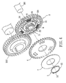
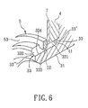
- the preferred embodiment of a motion transmitting apparatus includes a driving gear 202, a rotating shaft 201, a first driven gear 3 sleeved fixedly on the rotating shaft 201 and meshing with the driving gear 202, and an oil-lubricated gear clearance eliminating device.
- the first driven gear 3 has an annular flange 31 extending axially from an inner periphery thereof and having an annular outer surface 311 formed with an annular positioning groove 34.
- the gear clearance eliminating device includes a second driven gear 4 sleeved rotatably on the first driven gear 3 and meshing with the driving gear 202, a plurality of coiled compression springs 6 disposed between the first and second driven gears 3, 4 in a known manner for eliminating clearance between the driving gear 202 and an assembly of the first and second driven gears 3, 4 during rotation of the first and second driven gears 3, 4, and a ring plate 7 sleeved on the annular flange 31 for confining the spring 6 between the first and second driven gears 3, 4 in a known manner.
- the second driven gear 4 is disposed between the first driven gear 3 and the ring plate 7.
- the gear clearance eliminating device further includes a C-shaped retaining ring 5 received within the annular positioning groove 34 in the annular flange 31 so as to confine the second driven gear 4 and the ring plate 7 between the first driven gear 3 and the C-shaped retaining ring 5.
- the gear clearance eliminating device is disposed within an engine box.
- the first driven gear 3 further has a sleeve portion 30, from which the annular flange 31 extends, a central bore 301 defined by the sleeve portion 30 and permitting extension of the rotating shaft 201 therethrough, and a toothed portion 32 extending radially and outwardly from the sleeve portion 30.
- the annular outer surface 311 of the annular flange 31 is further formed with three angularly equidistant oil-receiving grooves 33 that extend along an axial direction of the annular flange 31, that cross the positioning groove 34, and that can receive lubricating oil.
- Each of the oil-receiving grooves 33 has an inner end 33' aligned with the second driven gear 4, and an open outer end 33" opposite to the inner end 33' .
- the gear clearance eliminating device may include only one oil-receiving groove 33.
- Each of the oil-receiving grooves 33 is defined by a bottom wall 334.
- the C-shaped retaining ring 5 has an inner peripheral surface 52 that is spaced apart from the bottom walls 334 of the oil-receiving grooves 33, so as to allow for flow of the lubricating oil within a space 333 between the inner peripheral surface 52 and each of the bottom walls 334.
- Each of the oil-receiving grooves 33 is divided by an outer side surface 53 of the C-shaped retaining ring 5 into an oil-storing area 331 and a lead-in area 332.
- the oil-storing area 331 of each of the oil-receiving grooves 33 is defined among the C-shaped retaining ring 5, the ring plate 7, the annular flange 31, and the second driven gear 4.
- each of the springs 6 is compressed to store a return force.
- the second driven gear 4 is biased by the springs 6 to rotate relative to the first driven gear 3 by a very small angle in an opposite direction to thereby eliminate clearance between the driving gear 202 and an assembly of the first and second driven gears 3, 4.
- the oil-lubricated gear clearance eliminating device of the motion transmitting apparatus of this invention has the following advantages:
Landscapes
- Engineering & Computer Science (AREA)
- General Engineering & Computer Science (AREA)
- Mechanical Engineering (AREA)
- General Details Of Gearings (AREA)
- Gear Transmission (AREA)
Applications Claiming Priority (1)
| Application Number | Priority Date | Filing Date | Title |
|---|---|---|---|
| TW99124355A TW201204964A (en) | 2010-07-23 | 2010-07-23 | Backlash eliminator with lubricant |
Publications (2)
| Publication Number | Publication Date |
|---|---|
| EP2410208A2 true EP2410208A2 (fr) | 2012-01-25 |
| EP2410208A3 EP2410208A3 (fr) | 2012-07-04 |
Family
ID=44851527
Family Applications (1)
| Application Number | Title | Priority Date | Filing Date |
|---|---|---|---|
| EP11174883A Withdrawn EP2410208A3 (fr) | 2010-07-23 | 2011-07-21 | Appareil de transmission de mouvement doté d'un dispositif d'élimination de jeu d'engrenage lubrifié avec de l'huile |
Country Status (2)
| Country | Link |
|---|---|
| EP (1) | EP2410208A3 (fr) |
| TW (1) | TW201204964A (fr) |
Cited By (6)
| Publication number | Priority date | Publication date | Assignee | Title |
|---|---|---|---|---|
| CN104358857A (zh) * | 2014-11-26 | 2015-02-18 | 安徽江淮汽车股份有限公司 | 一种变速箱齿轮啮合预紧结构 |
| US9664251B2 (en) | 2015-01-09 | 2017-05-30 | Deere & Company | Coupler for translating rotational forces |
| CN107120410A (zh) * | 2017-06-16 | 2017-09-01 | 盐城市禾鼎机械股份有限公司 | 一种消隙直齿轮 |
| CN108386527A (zh) * | 2018-03-27 | 2018-08-10 | 宝鸡法士特齿轮有限责任公司 | 一种可动态调节齿轮啮合侧隙的齿轮组 |
| CN108413014A (zh) * | 2018-03-27 | 2018-08-17 | 宝鸡法士特齿轮有限责任公司 | 一种六档变速器总成 |
| CN114483883A (zh) * | 2022-03-10 | 2022-05-13 | 苏州金亿精密齿轮有限公司 | 一种无侧隙啮合齿轮 |
Families Citing this family (1)
| Publication number | Priority date | Publication date | Assignee | Title |
|---|---|---|---|---|
| JP6166742B2 (ja) * | 2015-02-19 | 2017-07-19 | 株式会社豊田中央研究所 | 潤滑構造及び変速機 |
Family Cites Families (3)
| Publication number | Priority date | Publication date | Assignee | Title |
|---|---|---|---|---|
| JPS57189719A (en) * | 1981-05-11 | 1982-11-22 | Yanmar Diesel Engine Co Ltd | Working method of non-backlash gear |
| DE3901076A1 (de) * | 1988-01-28 | 1989-08-03 | Volkswagen Ag | Einrichtung zum zahnspiel-ausgleich |
| JPH08166055A (ja) * | 1994-10-12 | 1996-06-25 | Hino Motors Ltd | シザーズギヤの潤滑構造 |
-
2010
- 2010-07-23 TW TW99124355A patent/TW201204964A/zh unknown
-
2011
- 2011-07-21 EP EP11174883A patent/EP2410208A3/fr not_active Withdrawn
Non-Patent Citations (1)
| Title |
|---|
| None |
Cited By (8)
| Publication number | Priority date | Publication date | Assignee | Title |
|---|---|---|---|---|
| CN104358857A (zh) * | 2014-11-26 | 2015-02-18 | 安徽江淮汽车股份有限公司 | 一种变速箱齿轮啮合预紧结构 |
| US9664251B2 (en) | 2015-01-09 | 2017-05-30 | Deere & Company | Coupler for translating rotational forces |
| CN107120410A (zh) * | 2017-06-16 | 2017-09-01 | 盐城市禾鼎机械股份有限公司 | 一种消隙直齿轮 |
| CN107120410B (zh) * | 2017-06-16 | 2023-12-29 | 盐城市禾鼎机械股份有限公司 | 一种消隙直齿轮 |
| CN108386527A (zh) * | 2018-03-27 | 2018-08-10 | 宝鸡法士特齿轮有限责任公司 | 一种可动态调节齿轮啮合侧隙的齿轮组 |
| CN108413014A (zh) * | 2018-03-27 | 2018-08-17 | 宝鸡法士特齿轮有限责任公司 | 一种六档变速器总成 |
| CN114483883A (zh) * | 2022-03-10 | 2022-05-13 | 苏州金亿精密齿轮有限公司 | 一种无侧隙啮合齿轮 |
| CN114483883B (zh) * | 2022-03-10 | 2024-04-12 | 苏州金亿精密齿轮有限公司 | 一种无侧隙啮合齿轮 |
Also Published As
| Publication number | Publication date |
|---|---|
| TW201204964A (en) | 2012-02-01 |
| EP2410208A3 (fr) | 2012-07-04 |
Similar Documents
| Publication | Publication Date | Title |
|---|---|---|
| EP2410208A2 (fr) | Appareil de transmission de mouvement doté d'un dispositif d'élimination de jeu d'engrenage lubrifié avec de l'huile | |
| EP1813839A2 (fr) | Lubrification positive d'un engrenage moteur | |
| US8033941B2 (en) | Lubricating oil feeding device for automatic transmission | |
| US20070240964A1 (en) | Spring Clutch | |
| US10400873B2 (en) | Torsional vibration damper | |
| EP2562445A1 (fr) | Dispositif de poulie doté d'un élément amortissant | |
| CN111043279B (zh) | 一种惰齿轮装置及发动机 | |
| JP5968199B2 (ja) | 駆動力伝達装置の潤滑構造 | |
| JP2006144879A (ja) | 自動変速機用ピストン | |
| JPH08178004A (ja) | Vベルト式自動変速装置 | |
| JP2004239186A (ja) | 冷媒圧縮機 | |
| JP4369940B2 (ja) | 回転軸オイルシール部の潤滑構造 | |
| JP2003042195A (ja) | ワンウェイクラッチ装置 | |
| JP2014181721A (ja) | 歯車装置 | |
| JP2017155927A (ja) | 自動変速機の摩擦締結要素における潤滑構造 | |
| JP5812722B2 (ja) | 内燃機関の潤滑装置の構造 | |
| EP2562444A1 (fr) | Dispositif de poulie doté d'un élément de limitation de couple | |
| US9518640B2 (en) | Dry variable speed drive mechanism | |
| JP6499143B2 (ja) | 回転体のオイル排出構造 | |
| KR20180056007A (ko) | 피니언 샤프트 및 이를 구비하는 구동 장치 | |
| JP2013217480A (ja) | フリクションダンパ | |
| JP2013076419A (ja) | 車両用流体伝動装置 | |
| JP5192010B2 (ja) | 差動装置のデフケースにおける潤滑構造 | |
| JP6475221B2 (ja) | 遊星ギア装置 | |
| JP2001032855A (ja) | コーンクラッチ |
Legal Events
| Date | Code | Title | Description |
|---|---|---|---|
| AK | Designated contracting states |
Kind code of ref document: A2 Designated state(s): AL AT BE BG CH CY CZ DE DK EE ES FI FR GB GR HR HU IE IS IT LI LT LU LV MC MK MT NL NO PL PT RO RS SE SI SK SM TR |
|
| AX | Request for extension of the european patent |
Extension state: BA ME |
|
| PUAI | Public reference made under article 153(3) epc to a published international application that has entered the european phase |
Free format text: ORIGINAL CODE: 0009012 |
|
| PUAL | Search report despatched |
Free format text: ORIGINAL CODE: 0009013 |
|
| AK | Designated contracting states |
Kind code of ref document: A3 Designated state(s): AL AT BE BG CH CY CZ DE DK EE ES FI FR GB GR HR HU IE IS IT LI LT LU LV MC MK MT NL NO PL PT RO RS SE SI SK SM TR |
|
| AX | Request for extension of the european patent |
Extension state: BA ME |
|
| RIC1 | Information provided on ipc code assigned before grant |
Ipc: F16H 55/18 20060101AFI20120531BHEP Ipc: F16H 57/04 20100101ALI20120531BHEP |
|
| STAA | Information on the status of an ep patent application or granted ep patent |
Free format text: STATUS: THE APPLICATION IS DEEMED TO BE WITHDRAWN |
|
| 18D | Application deemed to be withdrawn |
Effective date: 20130105 |