EP2410623A2 - Module directionnel et système de tension d'un conducteur sur un pylône à haute tension - Google Patents
Module directionnel et système de tension d'un conducteur sur un pylône à haute tension Download PDFInfo
- Publication number
- EP2410623A2 EP2410623A2 EP11005633A EP11005633A EP2410623A2 EP 2410623 A2 EP2410623 A2 EP 2410623A2 EP 11005633 A EP11005633 A EP 11005633A EP 11005633 A EP11005633 A EP 11005633A EP 2410623 A2 EP2410623 A2 EP 2410623A2
- Authority
- EP
- European Patent Office
- Prior art keywords
- deflection
- module
- conductor
- mast
- voltage
- Prior art date
- Legal status (The legal status is an assumption and is not a legal conclusion. Google has not performed a legal analysis and makes no representation as to the accuracy of the status listed.)
- Withdrawn
Links
Images
Classifications
-
- H—ELECTRICITY
- H02—GENERATION; CONVERSION OR DISTRIBUTION OF ELECTRIC POWER
- H02G—INSTALLATION OF ELECTRIC CABLES OR LINES, OR OF COMBINED OPTICAL AND ELECTRIC CABLES OR LINES
- H02G1/00—Methods or apparatus specially adapted for installing, maintaining, repairing or dismantling electric cables or lines
- H02G1/02—Methods or apparatus specially adapted for installing, maintaining, repairing or dismantling electric cables or lines for overhead lines or cables
- H02G1/04—Methods or apparatus specially adapted for installing, maintaining, repairing or dismantling electric cables or lines for overhead lines or cables for mounting or stretching
Definitions
- the invention relates to a deflection module for a high-voltage conductor cable and a system for tensioning a conductor cable on high voltage pylons.
- high voltage power lines for example, for a voltage of 110kV or 380kV
- conductor cables are stretched between high-voltage masts, which - depending on the voltage level - have a distance of, for example, 100m to 400m.
- the ladder cables are connected by hanging insulators to the traverses of the high voltage masts.
- Power supply systems are usually three-phase, i. a ladder system consists of three individual ladders.
- a ladder system consists of three individual ladders.
- several conductor systems - in some cases also different voltage levels - are often mounted on a single mast.
- there is a ground wire which is led over the tips of the respective high voltage masts and which serves as lightning protection.
- An overhead line has to reduce the skin effect usually a plurality of layers of twisted conductors, wherein in the interior of the conductor to increase the tensile force, a steel core is woven and the surrounding conductor layers made of aluminum. Due to this structure of a conductor cable is especially during transport and assembly, make sure that it is not bent too much, otherwise damage to the rope would occur. As a rough guideline, it can be assumed that the minimum bending radius of the conductor does not fall below its 30-fold radius.
- a conductor As a multi-strand system, i. several parallel e.g. in a square with 30cm - 50cm edge length and provided with spacers arranged conductor cables are electrically connected in parallel, resulting in a ladder system of 3 phases already 12 individual conductors. This makes it particularly difficult to construct such an overhead line because according to the prior art each conductor cable is pulled individually onto the high-voltage mast.
- high-voltage masts are usually designed only as a support poles, which are not able to take on their hanging insulators horizontally acting on the ladder cable forces.
- Tie-down masts which can also intercept horizontal forces of the conductors due to their insulator arrangement, are usually provided only at a very large distance from each other. In order not to let these horizontal forces during the clamping process to be too large, it is either necessary to arrange the role with the exciting overhead line at a very large distance from the high voltage mast, for example, at a distance greater 120m.
- a deflection module for a high-voltage conductor cable, comprising an arcuate deflection channel, which is so pronounced that a conductor cable can be guided in this along its extension, a module holder with connection device, which is provided for releasably connected to a high voltage mast be and a spacer element through which a mechanically rigid connection between the deflection channel and module holder is formed.
- the idea according to the invention here is to make the high-voltage mast, by means of which the conductor cable is to be tensioned, fit to a guy mast by temporary installation of deflection modules so that its separate erection is eliminated.
- the designed as a support pole high-voltage mast as such is quite able to absorb horizontal forces, it is only the hanging insulator, which is not able by its hanging attachment to a single point of the crossmember of the mast, acting on the conductor rope carried by him horizontal forces intercept.
- This is effected according to the invention of the deflection modules to be mounted on the high-voltage mast. After the tensioning of the desired conductor cables, the deflection modules must then be removed again from the high-voltage mast.
- a deflection module initially has a deflection channel for the conductor cable to be clamped. This is necessary in order to be able to guide the conductor cable from the foot of the high-voltage mast to the desired position in the upper area.
- the deflection channel is to be designed such that the conductor cable along the Umlenkkanals is movable relative to the high-voltage mast. This allows pulling of the rope through the deflection channel.
- the deflection channel is also designed to execute in a radius of curvature, by which an excessive bending of the conductor cable is avoided. A bend of about 90 ° in a deflection channel is to be regarded as a typical size, which allows a particularly flexible cable guide along the high-voltage mast.
- the module holder with connecting device serves to establish a temporary and non-positive connection with the high-voltage mast.
- This can be, for example, a screw, clamp and / or plug connection, which are particularly easy to detach again.
- high voltage masts are usually designed as a grid structures with a variety of struts.
- a strut can namely be particularly easily enclosed by a connecting element in its diameter, so that a simple and secure connection can be realized.
- several connection points of a module holder with the high-voltage mast are possible, so as to realize a particularly stable connection.
- the spacer element serves to ensure a distance from the high-voltage mast to the deflection channel and thus to prevent possible contact with the tensioned conductor cable with the high-voltage mast.
- the deflection channel is at least partially formed by a respective segment portion of a freely rotatable roller with grooved recess for guiding the conductor along its circumference.
- a movement of a conductor cable through the deflecting channel formed at least in sections from the groove-shaped recess can be realized in a particularly simple and low-friction manner by a rotational movement of the roller. Even if, during a rotational movement of the roller, there is no relative movement to a conductor cable guided over the roller, this is to be regarded as movement of the conductor cable through a deflection channel.
- a plurality of freely rotatable rollers arranged parallel in a common plane and along an arc are provided, so that along the arc a polygon-like deflection channel is formed for a conductor cable.
- a plurality of deflection channels arranged in parallel are provided. This allows in particular the synchronous pulling of several conductors each through one of the deflection channels.
- the parallelism of the deflection channels is helpful in particular for the parallel guidance of several conductor cables from the ladder cable rollers to be provided on the mast base into the upper area of the mast, where the ropes are then inserted into the desired clamping positions.
- the spacer element is adaptable, so that a selectable distance and / or a selectable orientation of the deflection channel to the module holder can be realized.
- the desired conductor cable guide from the foot of the high-voltage mast in the upper region requires namely the arrangement of the deflection of the deflection modules at specific positions relative to the mast.
- the module holder of the deflection can only on the high-voltage mast, and this in particular on the lattice struts, mount, which sometimes only a certain, but not ideal for the conductor guide position or orientation is possible.
- a lockable telescopic extension of a spacer element or even a lockable rotary joint are devices that allow a correspondingly high flexibility in the installation of the deflection or in the conductor cable guide. But also the fixed mounting of additional intermediate, extension or kink pieces in the spacer achieved the same purpose.
- the first deflection module is arranged on the high-voltage mast that the first end of the Umlenkkanals the first Umlenkmoduls is aligned in the imaginary extension of the exciting conductor in its desired position on the high voltage mast and the second end of the Umlenkkanals preferably in vertical orientation.
- the conductor rope to be tensioned coming from the conductor pulley is first introduced vertically into the second end of the deflection channel, where it is deflected by approximately 90 ° and then at the first end of the Umlenkkanals in the pulling direction something in front of the insulator, which is to carry the ladder cable on the mast, executed approximately in a horizontal direction.
- the conductor cable is then pulled with the desired sag to the adjacent high-voltage mast to the corresponding comparable position.
- further deflection modules are arranged on the high-voltage mast in such a way that a conductor cable subjected to a tensile force can be guided mastnah from the foot of the high-voltage mast to a traverse located in the upper region and from there along the traverse to the second end of the deflection channel of the first deflection module is.
- the arrangement of the further deflection modules ensures a cable guide from the foot of the high-voltage mast to the first deflection module. This is very dependent on the shape of the mast.
- a deflecting module at the foot of the high-voltage mast may initially make sense in order to divert the conductor cable, which has been unwound horizontally from the conductor pulley, into a mast-proximate vertical.
- a further deflection module is to be provided, which guides the conductor cable into the outer region of the traverse.
- a deflection module is to be provided there, which feeds the conductor cable from the vertical direction, ie from above or below, to the first deflection module.
- deflection modules are provided with a plurality of parallel deflection channels, so that a plurality of conductor cables interconnected at their respective one end can be pulled together via the deflection modules.
- the conductors to be pulled synchronously are connected at their one end to a common connecting blade.
- the conductor cables are fastened in preferably equidistant spacing, which is adapted to the distances between the parallel deflection channels.
- a pull rope is centrally connected, with which the sword and the conductor cables can be pulled over the deflection modules.
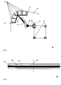
- Fig. 1 shows an exemplary system 10 for tensioning a conductor cable, in the illustrated variant for synchronously tensioning four conductor cables 28 on a mast 20, which for example has a height of 30m - 70m.
- the mast has two trusses 22, 24, wherein the four to exciting conductor cables 28 are to form a connected phase conductor of a 3-phase system and to be held at the outer end of the crossbar 24 by an insulator, not shown.
- the four ladder ropes are unwound and provided by a respective conductor pulley, as indicated by the reference numeral 26.
- the four conductor cables 28 are deflected close to the mast in an approximately vertical direction and guided in the upper mast area to the mounted there third deflection module 16, which in turn also has four parallel deflection channels.
- the plane of the four parallel conductors leads to a torsion of about 90 °, as indicated in the drawing.
- the conductor cables are now deflected in an approximately horizontal direction and guided to the left outer edge of the cross member 24 and there deflected a second deflection module 14 in the vertical and the first deflection module 12.
- the respective deflection modules are each connected to the mast 20 or its cross members 22, 24 with module holders and spacer elements, not shown. After tensioning the respective conductor cables, the deflection modules must be removed again.
- All deflection modules 12, 14, 16, 18 are each provided with four deflection channels, one deflection channel being assigned to one conductor cable in each case.
- the deflection channels are indicated in this case as a respective rotatable roller with groove-like depression, which of course, for example, also formed of a plurality of smaller and arranged on a circular path rollers polygon-like deflection channels are used.
- a slight offset of the parallel deflection channels is indicated in order to supply the conductor cables in each case exactly perpendicular to the corresponding deflection channel of the first deflection module 12. But this is not necessarily necessary. It is also conceivable that - as with the deflection modules 12, 16, 18 - all parallel deflection channels are arranged around the same imaginary axis of rotation.
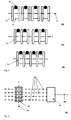
- Fig. 2 shows a first exemplary deflection module 40.
- This includes an arcuate deflection channel, the two ends are indicated by the reference numerals 57 and 58.
- the arcuate deflection channel is polygon similar approximated by a plurality of freely rotatable rollers 42 with groove-like depression, so that the minimum bending radius of the guided through the deflection channel 57-58 conductor cable 56 is not exceeded.
- rollers 42 By using the rollers 42, a movement of the conductor cable through the deflection channel is made possible in a particularly simple and low-friction manner.
- the six in a common plane arranged rotatable rollers 42 are connected via a common holder with a spacer 44 in this example.
- This has for geometrical adaptation to a length-adjustable cylinder 46 which can be locked in the desired length position, for example by a screw connection.
- the length-adjustable cylinder 46 in turn is connected at its opposite end with a device for adjusting the orientation, for example a ball joint with locking device.
- the two latter devices are optional components of the spacer element 44, which allow increased flexibility in the arrangement of the deflection module 40 on the high voltage mast - in this case on the struts 54 of a traverse.
- the device for adjusting the orientation 48 is connected to a module holder 50, which is non-positively connected to a high-voltage mast or the associated struts 54.
- a U-shaped bracket is provided, which encloses a strut in its cross section and is connected via a locking device releasably connected to a strut 54.
- the deflection module 40 is particularly easy to mount on a mast - also due to its reduced by using several smaller roles - weight - and disassemble again.
- Fig. 3 shows in comparison a roll with a large roller diameter 60, which is at least so large that the minimum bending radius - for example, 0.8 m - of the guided over the roller 62 conductor 68 is not exceeded.
- the roller 62 is rotatable about the axis of rotation 66 and has a groove-like recess 64, which in this case serves in sections as a deflection channel.
- Fig. 4 shows various roll variants with small roll diameter, which can be used to approximate the arc shape of several parallel Umlenkkanälen polygon similar.
- Reference numeral 70a shows four identical individual rollers 72, which are arranged around the same axis of rotation 82 and which guide a conductor cable 80 in a respective groove-like recess 78.
- Reference numeral 70b shows two double or tandem rollers 74, each guiding two conductor cables 80 in corresponding groove-like depressions.
- the reference number 70c shows a single quadrilateral roller 76, which has four groove-like recesses 78, in each of which a conductor cable 78 is guided. This figure illustrates that the assembly cost is advantageously reduced in such multiple roles.
- 2-, 3- or 5-fold variants are conceivable.
- the reference numeral 90 shows a connecting blade 92 with four conductor cables 100 and a pull cable 94.
- the four conductor cables 100 are hinted still guided by a quadruple roller 96 which is rotatable about a rotation axis 98.
- a connecting blade 92 it is particularly advantageous if the leadership of the conductors 100 from the foot of the high-voltage mast to the insertion point in the upper region of the mast, ie in the pulling direction shortly before the insulator, which is to carry the conductor, takes place in mutually parallel planes.
- connection sword 92 can be pulled with the pull cable 94 easily from the lower part of the high-voltage mast on all deflection to the upper part of the high-voltage mast and from there to all other pylons, where it pulls in this case four conductors by itself through all deflection channels.
- connection sword 92 realized, but it could possibly mean a certain additional effort in the leadership of the connection sword in the upper mast area.
Landscapes
- Suspension Of Electric Lines Or Cables (AREA)
- Installation Of Indoor Wiring (AREA)
Applications Claiming Priority (1)
| Application Number | Priority Date | Filing Date | Title |
|---|---|---|---|
| DE102010031722.5A DE102010031722B4 (de) | 2010-07-21 | 2010-07-21 | Umlenkmodul und System zum Spannen eines Leiterseils auf Hochspannungsmasten |
Publications (2)
| Publication Number | Publication Date |
|---|---|
| EP2410623A2 true EP2410623A2 (fr) | 2012-01-25 |
| EP2410623A3 EP2410623A3 (fr) | 2014-09-24 |
Family
ID=44720430
Family Applications (1)
| Application Number | Title | Priority Date | Filing Date |
|---|---|---|---|
| EP11005633.0A Withdrawn EP2410623A3 (fr) | 2010-07-21 | 2011-07-09 | Module directionnel et système de tension d'un conducteur sur un pylône à haute tension |
Country Status (2)
| Country | Link |
|---|---|
| EP (1) | EP2410623A3 (fr) |
| DE (1) | DE102010031722B4 (fr) |
Cited By (3)
| Publication number | Priority date | Publication date | Assignee | Title |
|---|---|---|---|---|
| EP2916405A1 (fr) * | 2013-11-19 | 2015-09-09 | European Trans Energy GmbH | Pont de protection |
| CN109713612A (zh) * | 2018-12-24 | 2019-05-03 | 江苏省送变电有限公司 | 迪尼玛绳高空收紧装置 |
| CN112234513A (zh) * | 2020-10-22 | 2021-01-15 | 谢晓佳 | 一种简易型线缆拉紧器 |
Family Cites Families (7)
| Publication number | Priority date | Publication date | Assignee | Title |
|---|---|---|---|---|
| FR1104834A (fr) * | 1954-05-06 | 1955-11-24 | Le Bois Bakelise | Perfectionnements apportés aux engins pour la mise en place des câbles de transport d'énergie électrique |
| DD281061A1 (de) * | 1989-03-31 | 1990-07-25 | Verbundnetze Energie Ve K | Vorrichtung zur montage von leiterseilen |
| DE19519773A1 (de) * | 1995-05-30 | 1996-12-05 | Siemens Ag | Verfahren zur Installation eines Lichtwellenleiter-Kabels an einer Hochspannungsfreileitung |
| DE19709727A1 (de) * | 1996-04-12 | 1997-10-30 | Siemens Ag | Verfahren zum Anbringen eines optischen Kabels an einer Freileitung und Einrichtung zur Durchführung des Verfahrens |
| DE19857131A1 (de) * | 1998-12-11 | 2000-06-15 | Alcatel Sa | Verfahren zur Installation eines Kabels an einem Seil einer Hochspannungsfreileitung |
| DE19937003B4 (de) * | 1999-08-06 | 2006-06-29 | Ltb Leitungsbau Gmbh | Verfahren und Vorrichtung zur Demontage von Freileitungsseilen |
| DE102005052612A1 (de) * | 2005-11-02 | 2007-05-03 | Hydro Aluminium Deutschland Gmbh | Verfahren zur Herstellung eines Hohlprofilverbunds |
-
2010
- 2010-07-21 DE DE102010031722.5A patent/DE102010031722B4/de active Active
-
2011
- 2011-07-09 EP EP11005633.0A patent/EP2410623A3/fr not_active Withdrawn
Non-Patent Citations (1)
| Title |
|---|
| None |
Cited By (4)
| Publication number | Priority date | Publication date | Assignee | Title |
|---|---|---|---|---|
| EP2916405A1 (fr) * | 2013-11-19 | 2015-09-09 | European Trans Energy GmbH | Pont de protection |
| CN109713612A (zh) * | 2018-12-24 | 2019-05-03 | 江苏省送变电有限公司 | 迪尼玛绳高空收紧装置 |
| CN109713612B (zh) * | 2018-12-24 | 2024-04-12 | 国家电网有限公司 | 迪尼玛绳高空收紧装置 |
| CN112234513A (zh) * | 2020-10-22 | 2021-01-15 | 谢晓佳 | 一种简易型线缆拉紧器 |
Also Published As
| Publication number | Publication date |
|---|---|
| DE102010031722B4 (de) | 2025-05-22 |
| EP2410623A3 (fr) | 2014-09-24 |
| DE102010031722A1 (de) | 2012-01-26 |
Similar Documents
| Publication | Publication Date | Title |
|---|---|---|
| EP2363314A1 (fr) | Dispositif de couplage de systèmes de caténaires électriques et fixes | |
| DE102017120764B4 (de) | Kran | |
| AT515083B1 (de) | Fahrleitungsmast für Oberleitungsanlagen elektrischer Schienenfahrzeuge | |
| EP2246952B1 (fr) | Dispositif de retenue pour une ligne aérienne et agencement de ligne aérienne | |
| DE102010031722A1 (de) | Umlenkmodul und System zum Spannen eines Leiterseils auf Hochspannungsmasten | |
| EP3581737A1 (fr) | Dispositif de maintien et de descente des câbles conducteurs d'une ligne aérienne | |
| EP2501006B1 (fr) | Installation de ligne aérienne, notamment pour lignes aériennes à haute tension | |
| DE102005009844B4 (de) | Hochspannungsleitung mit unterschiedlicher Aufhängehöhe der Seile einer Traverse und Verfahren zur Begrenzung der Magnetfelder | |
| DE202017107205U1 (de) | Befestigungsvorrichtung für Stromschienen | |
| EP2501007B1 (fr) | Installation de ligne aérienne, notamment pour lignes aériennes à haute tension | |
| DE19937003B4 (de) | Verfahren und Vorrichtung zur Demontage von Freileitungsseilen | |
| DE2628634C3 (de) | Drahtantennenanlage | |
| EP1826882B1 (fr) | Revêtement isolant pour une traverse de pylône de ligne électrique aérienne | |
| DE2705262C2 (de) | Vorrichtung zum Kurzschließen und Erden von Leitern eines mehrphasigen Hochspannungs-Freileitungssystems | |
| DE20007840U1 (de) | Seilzugschutztraverse | |
| DE10240432B4 (de) | Führungsrolle für Fahrdrahtzug am Seitenhalter | |
| DE202016104350U1 (de) | Aufhängeeinrichtung für eine Stromschiene einer Windkraftanlage und Anordnung mit einer Aufhängeeinrichtung | |
| DE7019955U (de) | Erdungsstange. | |
| EP3118054A1 (fr) | Suspension de barrette de connexion sur des poutres | |
| DE425750C (de) | Hochspannungsleitungsanlage | |
| DE2547596A1 (de) | Katenarische aufhaengung fuer leiter | |
| DE202017100725U1 (de) | Kabelbahnanschluss | |
| EP3303205B1 (fr) | Équipement de levage, en particulier câble de transmission | |
| DE1640846C3 (de) | Abspannvorrichtung für elektrische Hochspannungs-Freileitungsseile, insbesonere für teilisolierte Leiter | |
| DE9421833U1 (de) | Vorrichtung zum Auswechseln eines Mastkopfes eines Winkeltragmastes einer Hochspannungsfreileitung |
Legal Events
| Date | Code | Title | Description |
|---|---|---|---|
| AK | Designated contracting states |
Kind code of ref document: A2 Designated state(s): AL AT BE BG CH CY CZ DE DK EE ES FI FR GB GR HR HU IE IS IT LI LT LU LV MC MK MT NL NO PL PT RO RS SE SI SK SM TR |
|
| AX | Request for extension of the european patent |
Extension state: BA ME |
|
| PUAI | Public reference made under article 153(3) epc to a published international application that has entered the european phase |
Free format text: ORIGINAL CODE: 0009012 |
|
| PUAL | Search report despatched |
Free format text: ORIGINAL CODE: 0009013 |
|
| AK | Designated contracting states |
Kind code of ref document: A3 Designated state(s): AL AT BE BG CH CY CZ DE DK EE ES FI FR GB GR HR HU IE IS IT LI LT LU LV MC MK MT NL NO PL PT RO RS SE SI SK SM TR |
|
| AX | Request for extension of the european patent |
Extension state: BA ME |
|
| RIC1 | Information provided on ipc code assigned before grant |
Ipc: H02G 1/04 20060101AFI20140815BHEP |
|
| STAA | Information on the status of an ep patent application or granted ep patent |
Free format text: STATUS: THE APPLICATION IS DEEMED TO BE WITHDRAWN |
|
| 18D | Application deemed to be withdrawn |
Effective date: 20150325 |