EP2411230B1 - Als zeitung ausgebildetes druckprodukt - Google Patents
Als zeitung ausgebildetes druckprodukt Download PDFInfo
- Publication number
- EP2411230B1 EP2411230B1 EP10709515.0A EP10709515A EP2411230B1 EP 2411230 B1 EP2411230 B1 EP 2411230B1 EP 10709515 A EP10709515 A EP 10709515A EP 2411230 B1 EP2411230 B1 EP 2411230B1
- Authority
- EP
- European Patent Office
- Prior art keywords
- page
- printed product
- fold
- perforation
- cover sheet
- Prior art date
- Legal status (The legal status is an assumption and is not a legal conclusion. Google has not performed a legal analysis and makes no representation as to the accuracy of the status listed.)
- Not-in-force
Links
Images


Classifications
-
- B—PERFORMING OPERATIONS; TRANSPORTING
- B42—BOOKBINDING; ALBUMS; FILES; SPECIAL PRINTED MATTER
- B42D—BOOKS; BOOK COVERS; LOOSE LEAVES; PRINTED MATTER CHARACTERISED BY IDENTIFICATION OR SECURITY FEATURES; PRINTED MATTER OF SPECIAL FORMAT OR STYLE NOT OTHERWISE PROVIDED FOR; DEVICES FOR USE THEREWITH AND NOT OTHERWISE PROVIDED FOR; MOVABLE-STRIP WRITING OR READING APPARATUS
- B42D7/00—Newspapers or the like
-
- B—PERFORMING OPERATIONS; TRANSPORTING
- B41—PRINTING; LINING MACHINES; TYPEWRITERS; STAMPS
- B41F—PRINTING MACHINES OR PRESSES
- B41F13/00—Common details of rotary presses or machines
- B41F13/54—Auxiliary folding, cutting, collecting or depositing of sheets or webs
- B41F13/56—Folding or cutting
- B41F13/58—Folding or cutting lengthwise
-
- B—PERFORMING OPERATIONS; TRANSPORTING
- B65—CONVEYING; PACKING; STORING; HANDLING THIN OR FILAMENTARY MATERIAL
- B65H—HANDLING THIN OR FILAMENTARY MATERIAL, e.g. SHEETS, WEBS, CABLES
- B65H45/00—Folding thin material
- B65H45/12—Folding articles or webs with application of pressure to define or form crease lines
- B65H45/22—Longitudinal folders, i.e. for folding moving sheet material parallel to the direction of movement
-
- B—PERFORMING OPERATIONS; TRANSPORTING
- B42—BOOKBINDING; ALBUMS; FILES; SPECIAL PRINTED MATTER
- B42D—BOOKS; BOOK COVERS; LOOSE LEAVES; PRINTED MATTER CHARACTERISED BY IDENTIFICATION OR SECURITY FEATURES; PRINTED MATTER OF SPECIAL FORMAT OR STYLE NOT OTHERWISE PROVIDED FOR; DEVICES FOR USE THEREWITH AND NOT OTHERWISE PROVIDED FOR; MOVABLE-STRIP WRITING OR READING APPARATUS
- B42D1/00—Books or other bound products
- B42D1/003—Books or other bound products characterised by shape or material of the sheets
- B42D1/004—Perforated or punched sheets
- B42D1/005—Perforated or punched sheets having plural perforation lines, e.g. for detaching parts of the sheets
-
- B—PERFORMING OPERATIONS; TRANSPORTING
- B42—BOOKBINDING; ALBUMS; FILES; SPECIAL PRINTED MATTER
- B42D—BOOKS; BOOK COVERS; LOOSE LEAVES; PRINTED MATTER CHARACTERISED BY IDENTIFICATION OR SECURITY FEATURES; PRINTED MATTER OF SPECIAL FORMAT OR STYLE NOT OTHERWISE PROVIDED FOR; DEVICES FOR USE THEREWITH AND NOT OTHERWISE PROVIDED FOR; MOVABLE-STRIP WRITING OR READING APPARATUS
- B42D1/00—Books or other bound products
- B42D1/003—Books or other bound products characterised by shape or material of the sheets
- B42D1/006—Books or other bound products characterised by shape or material of the sheets with at least one foldable or folded sheet
-
- B—PERFORMING OPERATIONS; TRANSPORTING
- B42—BOOKBINDING; ALBUMS; FILES; SPECIAL PRINTED MATTER
- B42P—INDEXING SCHEME RELATING TO BOOKS, FILING APPLIANCES OR THE LIKE
- B42P2221/00—Books or filing appliances with additional arrangements
- B42P2221/06—Books or filing appliances with additional arrangements with information carrying means, e.g. advertisement
Definitions
- the invention relates to a printed product according to the preamble of claim 1.
- the attractiveness of the printed product can be further increased by the print product in addition to the print more features are added.
- the print product in addition to the print more features are added.
- perforation or by attaching an additional fold on the cover sheet new applications arise.
- DD 220 577 A1 It is known in a web-fed rotary printing press by means of a Pflugfalzes a more or less narrow strip of a web, for example, for advertising purposes, to fold longitudinally.
- a device is known with which a perforating knife, which perforates a web in a longitudinal direction, is arranged so that it can be adjusted in an arbitrary position in its position transversely to a web running direction.
- a printed product which is a side formed as a cover sheet, one connected via a center fold with the cover sheet, as
- a plow folding device By the DE 38 06 188 C1 a plow folding device is known, by means of which a printed product can be provided in addition to a middle fold with a further fold, which can be freely positioned with respect to a direction perpendicular to a transport direction of a printing material.
- a device is known by means of the printed products can be provided by means of a Pflugfalzes with a further fold in addition to a middle fold and by means of which the printed products can be provided with a perforation in a transport direction of a printing material.
- the devices for the further fold and the perforation can be adjusted.
- a printed product which serves as a deposit, wherein several glued together pages each have a perforation, all of which must be severed in order to remove the deposit as a whole from a publication can.
- a middle fold, further folds and perforations are parallel to each other.
- the insert is incorporated by means of back wire stitching in another document.
- About the perforations insert pages are associated with the printed product, which in turn are glued to the publication or connected by stapling with the publication.
- WO 99/30310 A1 It is known to combine different widths of substrate webs to a printed product, such as a newspaper, wherein different layers of the printing material webs are disclosed to each other. In this case, a narrower substrate web is always surrounded by a wider substrate web. It is also disclosed to arrange perforations parallel to a medial fold.
- the invention has for its object to provide an attractive printed product.
- the achievable with the present invention consist in particular in that on a cover sheet or a back of a printed product, such as a newspaper or a magazine, a part of a surface with an advertising message or another can be printed informative and / or decorative printed image and that by a perforation and a longitudinal fold a detachable printed product, such as a leaflet is created and that a title page is still preserved with its full surface.
- a detachable printed product or leaflet can be conspicuously but not disruptively placed, completely separated by a reader simply by severing a perforation and stored separately.
- a further advantage of the printed product is that an additional front fold or back side surface can be made variable by an additional longitudinal fold which is located anywhere relative to a width of the printed product.
- the perforation which is at an arbitrary position with respect to the width of the printed product, creates the possibility of either laying the perforation on the middle fold and thus the entire cover sheet or the entire back side of the latter to separate the remaining printed product or to leave part of the perforated cover sheet or the perforated back side.
- the remaining newspaper or magazine can be freed of visible traces after a separation of the folder or to create a different printed image in combination with the non-separated remainder of the perforated cover sheet or the perforated rear side.
- Another advantage is that after severing only one perforation, a portion of the printed product is completely detached from the remaining printed product.
- a further advantage of an embodiment is that at least one fold mark or pattern of fold marks is printed on the detachable fold sheet, so that a reader brings the separated fold sheet into an intended, practical format can.
- Such an application is very well suited, for example, to timetables, trade fair plans or any other printed product that the reader can take with them and possibly use for longer. As a result, this printed product, for example, even more attractive as a carrier of advertising messages.
- a further advantage is that, due to the additional fold, the area of the separable folder is greater than the area of the front page of the printed product covered by the unseparated folder.
- the entire area of the folded leaflet may even be larger than the area of the title page, although in the folded state of the printed product even a part of the title page is visible. Regardless of the other printed product or leaflet, the actual printed product can continue to be recognized by a customer at first glance without the advertisement hindering it.
- Another advantage is that, by choosing widths such that a folded-over substrate strip and a cover sheet each have half the width of the title page, all printing material webs used may have widths that correspond to integer multiples of a width used, for example, the title page.
- the printed product 01 which may be, for example, a newspaper 01 or a magazine 01, comprises at least one page 02 formed as a cover page 02, which is connected via a middle fold 03 with a side 04 formed as a back 04, and at least one intermediate, for example as Title page 09 trained page 09.
- This further fold 07 runs parallel to the middle fold 03.
- the further fold 07 produces a printing material strip 08, which points from the fold 07 in the direction of the middle fold 03.
- This printing material strip 08 can be folded over so that the printing material strip 08 itself between the back 04 and a not belonging to the substrate strip 08 part of the cover sheet 02 is, ie the fold 07 strikes the strip of printing material 08 inside.
- the printing material strip 08 can also be turned over in such a way that the part of the cover sheet 02 not belonging to the printing material strip 08 lies between the back side 04 and the folded-over printing material strip 08, ie the fold 07 strikes the printing material strip 08 to the outside.
- the cover sheet 02 is the part of the printed product 01 carrying the fold 07.
- the fold 07 can be located in a direction perpendicular to the middle fold 03 at an arbitrary distance from the center fold 03.
- a page 09 of the printed product 01 is referred to, which lies directly behind the cover sheet 02.
- results in a surface of the title page 09 which is visible in the folded state of the printed product 01 and results in a distance of an edge 11 of the embarked
- the strip of printing material 08 is exactly half as wide as the title page 09 and the edge 11 of the printing material strip 08 lies exactly on the middle fold 03 (FIG. Fig. 3a ).
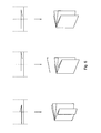
- FIG. 3 is, without limiting the invention thereto, for the purpose of better clarity of the additional fold each outwardly striking shown.
- a page 02; 04, which carries another fold 07, in the unfolded state is wider than the title page 09 of the printed product 01.
- the arrangement of an example web-shaped printing material 18 with respect to a direction B of its extension perpendicular to the transport direction A can be used to both the width of the Cover sheet 02 and the back 04 as well as the printing material strip 08 to vary.
- Partial width rear side 04 is less wide, such as the front page 09, which on a front of the printed product 01 in width more substrate 18 is available, which is divided on the substrate strip 08 and the remaining part of the cover sheet 02 can be ( Fig. 3b ) and c)). It is also possible to take advantage of variations in width of the substrate used for the sheet 06 18 further influence on the amount of substrate 18, which is available for the cover page 02 and the strip of printing material 08 available.
- a width of the printing material strip 08 and a width of the area covered by the cover page 02 of the title page 09 can be set as desired.
- the cover sheet 02 in the unfolded state may be wider, less wide, or as wide as the title page 09 (FIG. Fig. 3d )).
- Fig. 3 a denotes a width a of the title page 09 of the printed product 01, b a width b of the back 04, c a width c of the printing substrate strip 08 and d a width d of the part of the cover sheet 02 which does not belong to the printing material strip 08.
- a perforation 12 of the sheet 06 also runs parallel to the middle fold 03.
- a distance of the perforation 12 from the middle fold 03 is arbitrary.
- the distance of the perforation 12 from the center fold 03 is in a special relationship to a choice of the width of the printing material strip 08 and the distance of the fold 07 from the middle fold 03.
- the perforation 12 is on the cover sheet 02 and the back 04 forming Sheet 06 in a range of one third of a width of the title page 09 around the middle fold.
- the perforation 12 lies exactly on the center fold 03, so that the cover sheet 02 can be completely separated as a leaflet 13 and the remaining printed product 01 has at most small traces of a part of the printed product 01 has been removed.
- the perforation 12 in a tolerance range, preferably of 2 cm and more preferably of 0.5 cm, may lie around the middle fold 03, for example, to increase the stability of the unseparated printed product 01 and / or to keep inconspicuous after a separation remaining edge strips.
- the perforation 12 is not exactly on the middle fold 03, so is the perforation 12 having side 02; 04 at least formed a fold 07 supporting.
- the distance of the perforation 12 from the middle fold 03 is matched to the printed image of the cover sheet 02 and the front page 09, so that after removing the leaflet 13 from the non-separated part of the cover sheet 02 and the non-covered part of the title page 09 gives an intended overall picture.
- the perforation 12 is located on the same side 02; 04 like the fold 07 ( Fig. 4 ).
- the perforation 12 is arranged so that the leaflet 13 is connected only over a line along the perforation 12 with the rest of the printed product 01 and is completely solved by severing the perforation 12 of the printed product 01. This means that, for example, in the case of a newspaper, the leaflet 13 is no longer in contact with a side which is in contact with other sides via the middle fold 03.
- the part 13 of the cover sheet 02 which is separable as a folded sheet 13 is printed with at least one folding mark 14, so that the separated sheet 13 can be made smaller in a manner intended.
- a leaflet to a newspaper 01, which can be taken and used by the reader in the folded state for a long time, for example a trade fair layout or something similar.
- Fig. 2 There are various applications and embodiments conceivable ( Fig. 2 ).
- folds 07 and / or one or more perforations 12 on the cover sheet 02 and / or on the back 04.
- the folds 07 can thereby strike appropriate printing material strips 08 inwards or outwards.
- sides of the printed product 01 lying further inside the printed product 01 are provided with folds 07 and perforations 12.
- printed on the cover sheet 02 printed image is upside down compared to a printed on the front page 09 print image, d. H. is twisted by an angle of 180 °.
- the described printed product 01 can be produced with a device for a printing press, wherein the device comprises at least one perforating device 26, in particular a perforating knife 26 or shortly knife 26, which is in a direction B perpendicular to a transport direction A of a printing material 18, which is preferably web-shaped is adjustable in a freely selectable position and wherein the device further comprises at least one Pflugfalzvorides 16 which is adjustable in the direction B also in a freely selectable position. It is conceivable both for the perforating device 26 and for the Pflugfalzvorides 16, an adjusting mechanism by hand, by means of a controllable device and / or by means of a machine control remote control is operable.
- At least one printing material web 18 is processed both by the perforating device 26 and by the Pflugfalzvorraum 16.
- the perforating device 26 and the Pflugfalzvorides 16 are mounted in the transport direction A of the printing material 18 after a means for printing the substrate 18 and more preferably the perforator 26 is mounted in the transport direction A of the printing material 18 in front of the Pflugfalzvorraum 16.
- This facilitates attachment of the perforation 12 and attachment of a fold 03 or middle fold 03 on at least one and the same line and prevents unwanted double perforation 12 at one another
- a method for producing the printed product 01 will be described below.
- a height of the finished printed product 01 ie a dimension parallel to the middle fold 03, is parallel to the transport direction A of the printing material 18 during the production process, which is present here in the form of a printing material web 18 or web 18 for short.
- pages 09 of the print product 01 which are not to be perforated and have an additional fold are processed in the usual way, i. H.
- the corresponding printing material webs 18 are printed, optionally perforated, optionally longitudinally cut, webs 18 and / or partial webs 18 are superimposed and the superimposed webs 18 and / or partial webs 18 are fed as a strand of a folder forming device, at the desired location, ie usually in a middle of the strand that provides strand with the midfold 03.
- the folded strands are processed further, for example, cut transversely, further folded and so on. It is also possible to carry out method steps other than those specified here, and a sequence of method steps is not limited to that described above.
- the web 18, which is to carry a perforation 12 and another fold 07, is also printed, wherein the printed image may also include folding marks 14.
- This is followed by various steps: possibly cutting the web 18 parallel to the transport direction A, perforating the web 18 parallel to the transport direction A with the aid of a perforating knife 26 described above, which position is perpendicular to the transport direction A of the web 18, arranging a fold 07 along the Transport direction A by means of a Pflugfalzvorraum 16, aligning the web 18 perpendicular to its transport direction A, for example by means of turning bars, feeding the folded and perforated web 18 to the remaining strand and Joint transport of the strand to the former.
- the order here is not determined as described above, for example, an orientation of the web 18 may also take place before the attachment of the perforation 12 or before the action of the Pflugfalzvorraum 16.
- the operation of the Pflugfalzvoriques 16 for attaching a longitudinal fold is the following: by means of a corresponding Pflugfalzvoriques 16 is a part 17 of a web 18, which is transported in a transport direction A, initially bent or kinked relative to the rest of the web 18, in such a way that a line 19 from one end 21 to the other end 22 of the web 18, along the web 18 and in a direction B perpendicular to its transport direction A, is no longer a straight line 19 but has a bend 23 or a bend 23.
- the bending or buckling is, as far as continued along the transport path of the web 18 until the one end 21 of the line 19 and the other end 22 of the line 19 in a same direction perpendicular to the transport direction A of the web 18.
- a device 24 is attached, which presses the bent or kinked portion 17 of the web 18 to the other part of the web 18 and thus produces a pronounced fold 07.
- a preferred example of such a device 24 is a pair of rollers 24, which has only a small gap through which the web 18 or a bent portion 17 of the web 18 is at least passed to the point at which the fold 07 is to arise.
- the rollers of the roller pair 24 are preferably so wide that the complete web 18 is transported through the gap.
- the folded through the fold 07 part 17 of the web 18 in the finished printed product 01 inwardly or outwardly.
- the perforation 12 of the printed product 01 preferably takes place in the following manner: a perforating device 26 designed as a perforating knife 26, which is designed as a circular knife 26 with a non-continuous cutting edge along its circumference, is rotatably mounted about an axis of rotation 27. It is made to the web 18 in the way that a rotation axis 27 of the blade 26 is perpendicular to the transport direction A of the web 18 and a peripheral speed of the blade 26 and a transport speed of the web 18 are matched. This results in a perforation 12 along the transport direction A of the web 18.
- a printed product 01 produced in tabloid format can be produced according to the above description only if the perforation 12 runs perpendicular to the transport direction A in the production process. In this case, however, the use of other means for attaching the fold 07 is necessary, since this then also perpendicular to the transport direction A of the web 18 runs.
- the printed product as described above and in kind as well as in Fig.
- the webs 18 and / or partial webs 18 may be merged, inter alia, that each side edge of a first substrate web 18 in the direction B, perpendicular to the transport direction A of the printing material webs 18, offset from each side edge of a second substrate web 18.
- web 18 or partial web 18 perpendicular to its transport direction A for example by turning bars, different layers or widths of, generated by this partial web 18, pages 02; 04 of the printed product 01 relative to the remaining pages 09 of the printed product 01 are generated.
- a method for producing the printed product 01 is used, in which at least two printing material webs 18 are brought together and guided over the former, whereby at least on one of these printing material webs 18 of the middle fold 03 is attached, at least this one printing material 18 before attaching the Mittelfalzes 03, by means of the perforator 26 is provided parallel to the middle fold 03 with the perforation 12 and wherein this is passed a printing material 18 after attaching the perforation 12 and before attaching the middle fold 03 on the Pflugfalzvorides 16 and thereby the further fold 07, the is parallel to the middle fold 03, attached to this printing substrate 18 is and after being guided over the Pflugfalzvorraum 16 and before attaching the middle fold 03, the at least two printing material webs 18 are merged by a printing material 18, which still carries no fold, from one, a folded from the other fold 07 substrate strip 08 side facing away is applied to the further fold 07 supporting substrate web 18 and wherein the further fold 07 supporting substrate web 18 is provided by the former with exactly one middle fold
- the method is preferably an in-line method and preferably includes preliminary steps which serve, for example, printing and / or painting of the printing material 18 in at least one printing unit and / or at least one coating unit and / or subsequent steps, for example, cutting and / or transverse folds of the printing material 18 serve for example in a folder.
- an in-line method is a method in which all method steps are carried out consecutively without the printing material 18 remaining stationary.
- one or more of the printing material webs 18 are partial webs of at least one printing material web 18.
- the printing material web 18, which is provided by means of the Pflugfalzvorraum 16 with the additional fold 07 a width corresponding to a double width of a page in a broadsheet format.
- Such a width in broadsheet format corresponds, for example, to the width a of the title page 09.
- the printing material web 18 may be a partial web of a originally, for example, four or six pages in broadsheet format broad substrate web 18. Other partial webs of the same printing material web 18 can then also be incorporated into the production of the same printed product.
- the printing material webs 18 are at least partially glued or stapled, so that a firmly cohesive printed product is formed, of which a part can be separated by severing the perforation.
Landscapes
- Engineering & Computer Science (AREA)
- Mechanical Engineering (AREA)
- Folding Of Thin Sheet-Like Materials, Special Discharging Devices, And Others (AREA)
- Credit Cards Or The Like (AREA)
Description
- Die Erfindung betrifft ein Druckprodukt gemäß dem Oberbegriff des Anspruches 1.
- Bei der Produktion eines Druckprodukts, beispielsweise einer Zeitung oder einer Zeitschrift, kann die Attraktivität des Druckprodukts weiter gesteigert werden, indem dem Druckprodukt neben dem Bedruck noch weitere Merkmale zugefügt werden. So können beispielsweise durch Perforierung oder durch das Anbringen eines zusätzlichen Falzes auf dem Deckblatt neue Einsatzmöglichkeiten entstehen.
- Durch die
DD 220 577 A1 - Durch die
EP 1 040 013 B1 ist ein Verfahren zur Herstellung einer Zeitung bekannt, bei dem vor dem Querscheiden einer Teilwarenbahn eine Perforierung, die über eine gesamte Höhe einer Seite durchgeht, in die Teilwarenbahn eingebracht wird. - Durch die
DE 10 2007 019 864 A1 ist eine Vorrichtung bekannt, mit der ein, eine Bahn in einer Längsrichtung perforierendes, Perforiermesser so angebracht ist, dass es in seiner Position quer zu einer Bahnlaufrichtung an einer beliebigen Position einstellbar ist. - Durch die
DE 36 15 121 A1 ist es bekannt, eine Längsfalzvorrichtung und eine Perforiervorrichtung in einer Druckmaschine anzuordnen. - Durch die
US 5 799 979 A ist ein Druckprodukt bekannt, das eine als Deckblatt ausgebildete Seite, eine über einen Mittelfalz mit dem Deckblatt verbundene, als - Rückseite ausgebildete, Seite und zumindest eine dazwischen liegende, als Titelseite ausgebildete, Seite umfasst, wobei ein, das Deckblatt und die Rückseite bildender, Bogen parallel zu dem, das Deckblatt mit der Rückseite verbindenden, Mittelfalz zumindest einen weiteren Falz aufweist und wobei der, das Deckblatt und die Rückseite bildende, Bogen parallel zu dem, das Deckblatt mit der Rückseite verbindenden, Mittelfalz zumindest eine Perforierung aufweist.
- Durch die
DE 38 06 188 C1 ist eine Pflugfalzvorrichtung bekannt, mittels der ein Druckprodukt zusätzlich zu einem Mittelfalz mit einem weiteren Falz versehen werden kann, der bezüglich einer Richtung senkrecht zu einer Transportrichtung eines Bedruckstoffs frei positioniert werden kann. - Durch die
EP 1 604 931 A2 ist eine Vorrichtung bekannt, mittels der Druckprodukte mittels eines Pflugfalzes mit einem weiteren Falz zusätzlich zu einem Mittelfalz versehen werden können und mittels der die Druckprodukte mit einer Perforation in einer Transportrichtung eines Bedruckstoffs versehen werden können. Die Vorrichtungen für den weiteren Falz und die Perforation können dabei verstellt werden. - Durch die
DE 30 16 573 A1 ist ein Druckprodukt bekannt, das als Einlage dient, wobei mehrere zusammengeklebte Seiten jeweils eine Perforation aufweisen, die sämtlich durchtrennt werden müssen, um die Einlage als ganzes aus einer Druckschrift entnehmen zu können. Ein Mittelfalz, weitere Falze und Perforationen liegen parallel zueinander. Die Einlage wird mittels Rückdrahtheftung in eine weitere Druckschrift eingebunden. Über die Perforationen sind Einlegeseiten mit dem Druckprodukt verbunden, die wiederum mit der Druckschrift verklebt oder durch Heftung mit der Druckschrift verbunden sind. - Durch die
US 4 340 212 A ist ein Druckprodukt bekannt, das einen Mittelfalz und zwei weitere, dazu parallele Falze und zwei dazu parallele Perforierungen aufweist. Es handelt sich dabei um Briefumschläge, die als insert" in einem zweiten Druckprodukt angeordnet werden. Die Briefumschläge sind nur über eine Linie entlang der Perforierung mit dem restlichen Druckprodukt verbunden und durch Durchtrennen der Perforierung von dem zweiten Druckprodukt vollständig lösbar. - Durch die
WO 99/30310 A1 - Der Erfindung liegt die Aufgabe zugrunde, ein attraktives Druckprodukt zu schaffen.
- Die Aufgabe wird erfindungsgemäß durch die Merkmale des Anspruches 1 gelöst.
- Die mit der Erfindung erzielbaren Vorteile bestehen insbesondere darin, dass auf einem Deckblatt oder einer Rückseite eines Druckprodukts, beispielsweise einer Zeitung oder einer Zeitschrift, ein Teil einer Fläche mit einer Werbebotschaft oder einem anderen informativen und/oder dekorativen Druckbild bedruckt sein kann und dass durch eine Perforierung und einen Längsfalz ein abtrennbares Druckprodukt, beispielsweise ein Faltblatt entsteht und dass eine Titelseite trotzdem mit ihrer vollen Fläche erhalten bleibt. Dadurch kann das abtrennbare Druckprodukt bzw. Faltblatt auffällig aber nicht störend platziert, von einem Leser einfach mittels Durchtrennen einer Perforation vollständig abgetrennt und separat aufbewahrt werden.
- Ein weiterer Vorteil des Druckprodukts besteht darin, dass durch einen zusätzlichen Längsfalz, der bezüglich einer Breite des Druckprodukts an einer beliebigen Stelle liegt, eine von dem abtrennbaren Faltblatt bedeckte Fläche der Titelseite oder einer Rückseite variabel gestaltet werden kann.
- Ein weiterer Vorteil des Druckprodukts besteht darin, dass durch die Perforierung, die bezüglich der Breite des Druckprodukts an einer beliebigen Stelle liegt, die Möglichkeit geschaffen wird, entweder die Perforierung auf den Mittelfalz zu legen und damit das gesamte Deckblatt bzw. die gesamte Rückseite von dem restlichen Druckprodukt abzutrennen oder einen Teil des perforierten Deckblatts bzw. der perforierten Rückseite stehen zu lassen. Dadurch kann beispielsweise die übrige Zeitung oder Zeitschrift nach einem Abtrennen des Faltblattes von sichtbaren Spuren befreit sein oder auch in Kombination mit dem nicht abgetrennten Rest des perforierten Deckblattes bzw. der perforierten Rückseite ein anderes Druckbild zu schaffen.
- Ein weiterer Vorteil besteht darin, dass nach einem Durchtrennen lediglich einer Perforierung ein Teil des Druckprodukts vollständig von dem restlichen Druckprodukt gelöst ist.
- Ein weiterer Vorteil einer Ausführungsform besteht darin, dass auf dem abtrennbaren Faltblatt zumindest eine Faltmarke oder ein Muster aus Faltmarken abgedruckt ist, so dass ein Leser das abgetrennte Faltblatt in ein vorgesehenes, praktisches Format bringen kann. Eine solche Anwendung eignet sich beispielsweise sehr gut für Fahrpläne, Messepläne oder beliebige andere Druckprodukte, die der Leser mitnehmen und eventuell länger benutzen kann. Dadurch wird dieses Druckprodukt beispielsweise auch als Träger von Werbebotschaften noch attraktiver.
- Ein weiterer Vorteil besteht darin, dass durch den zusätzlichen Falz die Fläche des abtrennbaren Faltblattes größer ist, als die von dem unabgetrennten Faltblatt bedeckte Fläche der Titelseite des Druckprodukts. So kann die gesamte Fläche des aufgefalteten Faltblatts sogar größer sein, als die Fläche der Titelseite, obwohl im zusammengefalteten Zustand des Druckprodukts sogar noch ein Teil der Titelseite sichtbar ist. Unabhängig von dem weiteren Druckprodukt bzw. Faltblatt kann dadurch das eigentliche Druckprodukt weiterhin auf den ersten Blick von einem Kunden erkannt werden, ohne dass die Werbung ihn dabei behindern würde.
- Ein weiterer Vorteil besteht darin, dass durch eine Wahl von Breiten derart, dass ein umgeschlagener Bedruckstoffstreifen und ein Deckblatt jeweils die Hälfte der Breite der Titelseite aufweisen, alle verwendeten Bedruckstoffbahnen Breiten aufweisen können, die ganzzahligen Vielfachen einer verwendeten Breite, beispielsweise der Titelseite, entsprechen.
- Ausführungsbeispiele der Erfindung sind in den Zeichnungen dargestellt und werden im Folgenden näher beschrieben.
- Es zeigen:
- Fig. 1
- eine schematische Darstellung eines Druckprodukts;
- Fig. 2
- eine schematische Darstellung eines vom restlichen Druckprodukt abgetrennten Faltblatts;
- Fig. 3
- Beispiele möglicher Varianten a), b), c), und d) bezüglich eines Abstandes eines zusätzlichen Falzes von einem Mittelfalz sowie einer Breite einer Deckseite, einer Rückseite und eines Bedruckstoffstreifens;
- Fig. 4
- eine schematische Darstellung einer Abbildung auf einem Deckblatt und einer Abbildung auf einer Titelseite, die in Kombination eine gemeinsame Abbildung erzeugen, und zwar auf verschiedene Arten, je nachdem, ob ein mittels Perforierung abtrennbares Faltblatt vom restlichen Druckprodukt abgetrennt ist oder nicht;
- Fig. 5
- eine schematische Darstellung einer Pflugfalzvorrichtung, einer Perforiervorrichtung und einer von diesen beiden bearbeiteten Bedruckstoffbahn;
- Fig. 6
- Ausführungsbeispiele für eine Ausrichtung einer, mit einem zusätzlichen Falz versehenen, Bedruckstoffbahn relativ zu einer anderen Bedruckstoffbahn und daraus entstehende Druckprodukte.
- Die folgenden Erläuterungen eines Druckprodukts 01 beziehen sich auf ein Druckprodukt 01 in einem vollständig zusammengeklappten Zustand. Das Druckprodukt 01, das beispielsweise eine Zeitung 01 oder eine Zeitschrift 01 sein kann, umfasst zumindest eine als Deckblatt 02 ausgebildete Seite 02, die über einen Mittelfalz 03 mit einer als Rückseite 04 ausgebildeten Seite 04 verbunden ist, sowie zumindest eine dazwischen liegende, beispielsweise als Titelseite 09 ausgebildete Seite 09. Ein Bogen 06 aus Bedruckstoff 18, vorzugsweise aus Papier, der das Deckblatt 02 und die Rückseite 04 bildet, weist neben dem Mittelfalz 03 noch zumindest einen weiteren Falz 07 auf. Dieser weitere Falz 07 verläuft parallel zum Mittelfalz 03. Durch den weiteren Falz 07 entsteht ein Bedruckstoffstreifen 08, der vom Falz 07 aus in Richtung Mittelfalz 03 weist. Dieser Bedruckstoffstreifen 08 kann so umgeschlagen sein, dass der Bedruckstoffstreifen 08 sich zwischen der Rückseite 04 und einem nicht zum Bedruckstoffstreifen 08 gehörenden Teil des Deckblattes 02 befindet, d. h. der Falz 07 schlägt den Bedruckstoffstreifen 08 nach innen. Der Bedruckstoffstreifen 08 kann aber auch so umgeschlagen sein, dass der nicht zum Bedruckstoffstreifen 08 gehörende Teil des Deckblatts 02 zwischen der Rückseite 04 und dem umgeschlagenen Bedruckstoffstreifen 08 liegt, d. h. der Falz 07 schlägt den Bedruckstoffstreifen 08 nach außen. In beiden Fällen ist das Deckblatt 02 der, den Falz 07 tragende, Teil des Druckprodukts 01. (
Fig. 1 und 2 ) - Der Falz 07 kann sich in einer Richtung senkrecht zum Mittelfalz 03 in einem beliebigen Abstand vom Mittelfalz 03 befinden. Mit einer Titelseite 09 wird eine Seite 09 des Druckprodukts 01 bezeichnet, die direkt hinter dem Deckblatt 02 liegt. Je nachdem, wie breit der Bogen 06 ursprünglich ist und in welchem Abstand zum Mittelfalz 03 sich der Falz 07 befindet, ergibt sich eine Fläche der Titelseite 09, die im zusammengefalteten Zustand des Druckproduktes 01 sichtbar ist und ergibt sich ein Abstand einer Kante 11 des eingeschlagenen Bedruckstoffstreifens 08 zum Mittelfalz 03 und ergibt sich eine Breite des Bedruckstoffstreifens 08. Es ist möglich, die Kante 11 auf den Mittelfalz 03 zu schlagen und somit eine Fläche des abtrennbaren Faltblatts 13 im ausgeklappten Zustand zu erzeugen, die doppelt so groß ist, wie eine von dem unabgetrennten Faltblatt 13 bedeckte Fläche der Titelseite 09. In einer bevorzugten Ausführungsform ist der Bedruckstoffstreifen 08 genau halb so breit wie die Titelseite 09 und liegt die Kante 11 des Bedruckstoffstreifens 08 genau auf dem Mittelfalz 03 (
Fig. 3a ). In derFig. 3 ist, ohne die Erfindung darauf zu beschränken, zum Zweck einer besseren Übersichtlichkeit der zusätzliche Falz jeweils nach außen schlagend dargestellt. Es ist aber auch möglich, dass eine Seite 02; 04, die einen weiteren Falz 07 trägt, im ausgeklappten Zustand breiter ist, als die Titelseite 09 des Druckprodukts 01. Auch die Anordnung eines beispielsweise bahnförmigen Bedruckstoffs 18 bezüglich einer Richtung B seiner Ausdehnung senkrecht zur Transportrichtung A kann dazu verwendet werden, sowohl die Breite des Deckblatts 02 und der Rückseite 04 als auch des Bedruckstoffstreifens 08 zu variieren. So kann beispielsweise durch entsprechende Verschiebung des Bedruckstoffes 18 nur eine teilbreite Rückseite 04 angeordnet werden, d. h. die Rückseite 04 ist weniger breit, als beispielsweise die Titelseite 09, wodurch auf einer Vorderseite des Druckprodukts 01 in der Breite mehr Bedruckstoff 18 zur Verfügung steht, der auf den Bedruckstoffstreifen 08 und den restlichen Teil des Deckblattes 02 aufgeteilt werden kann (Fig. 3b ) und c) ). Es ist ebenfalls möglich, durch Variationen in einer Breite des für den Bogen 06 eingesetzten Bedruckstoffes 18 weiteren Einfluss auf die Menge an Bedruckstoff 18 zu nehmen, die für die Deckseite 02 und den Bedruckstoffstreifen 08 zur Verfügung steht. Durch Kombination der beiden Möglichkeiten, also einer Verschiebung des Bedruckstoffes 18 und einer Variation der Breite des Bedruckstoffs 18, können eine Breite des Bedruckstoffstreifens 08 und eine Breite der von der Deckseite 02 bedeckten Fläche der Titelseite 09 beliebig eingestellt werden. Beispielsweise kann das Deckblatt 02 im ausgeklappten Zustand breiter, weniger breit oder genauso breit sein, wie die Titelseite 09 (Fig. 3d ) ). InFig. 3 bezeichnet a eine Breite a der Titelseite 09 des Druckproduktes 01, b eine Breite b der Rückseite 04, c eine Breite c des Bedruckstoffstreifens 08 und d eine Breite d des Teils des Deckblatts 02, der nicht zum Bedruckstoffstreifen 08 gehört. - Eine Perforierung 12 des Bogens 06 verläuft ebenfalls parallel zum Mittelfalz 03. Auch ein Abstand der Perforierung 12 vom Mittelfalz 03 ist beliebig wählbar. Bevorzugt steht der Abstand der Perforierung 12 vom Mittelfalz 03 in einem speziellen Zusammenhang zu einer Wahl der Breite des Bedruckstoffstreifens 08 und dem Abstand des Falzes 07 vom Mittelfalz 03. In einer bevorzugten Ausführungsform liegt die Perforierung 12 auf dem das Deckblatt 02 und die Rückseite 04 bildenden Bogen 06 in einem Bereich von einem Drittel einer Breite der Titelseite 09 um den Mittelfalz. In einer anderen bevorzugten Ausführungsform liegt die Perforierung 12 genau auf dem Mittelfalz 03, so dass das Deckblatt 02 komplett als ein Faltblatt 13 abgetrennt werden kann und das übrige Druckprodukt 01 höchstens noch geringe Spuren davon aufweist, dass ein Teil des Druckprodukts 01 entfernt wurde. Wenn dabei von einer Lage der Perforierung 12 genau auf dem Mittelfalz 03 bzw. auf dem Mittelfalz 03 die Rede ist, so ist gemeint, dass die Perforierung 12 in einem Toleranzbereich, bevorzugt von 2 cm und weiter bevorzugt von 0,5 cm, um den Mittelfalz 03 liegen kann, beispielsweise um eine Stabilität des ungetrennten Druckprodukts 01 zu erhöhen und/oder einen nach einer Trennung übrigen Randstreifen unauffällig zu halten. Wenn also die Perforierung 12 nicht exakt auf dem Mittelfalz 03 liegt, so ist bevorzugt die die Perforierung 12 aufweisende Seite 02; 04 zumindest einen Falz 07 tragend ausgebildet. In einer anderen bevorzugten Ausführungsform ist der Abstand der Perforierung 12 vom Mittelfalz 03 auf das Druckbild des Deckblattes 02 und der Titelseite 09 abgestimmt, so dass sich nach Entfernen des Faltblatts 13 aus dem nicht abgetrennten Teil des Deckblatts 02 und dem nicht verdeckten Teil der Titelseite 09 ein beabsichtigtes Gesamtbild ergibt. Bevorzugt befindet sich die Perforierung 12 auf der gleichen Seite 02; 04 wie der Falz 07 (
Fig. 4 ). Bevorzugt ist die Perforierung 12 so angeordnet, dass das Faltblatt 13 nur über eine Linie entlang der Perforierung 12 mit dem restlichen Druckprodukt 01 verbunden ist und bei Durchtrennen der Perforierung 12 von dem Druckprodukt 01 vollständig gelöst ist. Das bedeutet, dass das Faltblatt 13 beispielsweise im Fall einer Zeitung nicht mehr mit einer Seite in Kontakt steht, die über den Mittelfalz 03 mit anderen Seiten in Kontakt steht. - In einer anderen bevorzugten Ausführungsform ist der als Faltblatt 13 abtrennbare Teil des Deckblatts 02 mit zumindest einer Faltmarke 14 bedruckt, so dass das abgetrennte Faltblatt 13 in einer vorgesehenen Weise in ein kleineres Format gebracht werden kann. Somit ist es beispielsweise möglich, einer Zeitung 01 eine Beilage beizufügen, die vom Leser im gefalteten Zustand längere Zeit mitgenommen und verwendet werden kann, beispielsweise ein Messeplan oder etwas ähnliches. Es sind verschiedenste Anwendungen und Ausführungsformen denkbar (
Fig. 2 ). - Es ist auch möglich, den zusätzlichen Falz 07 und gegebenenfalls die Perforierung 12 auf der Rückseite 04 anzubringen. Alle oben genannten Details und Ausführungsbeispiele lassen sich entsprechend übertragen, so ist dann beispielsweise mit dem, den Falz 07 tragenden, Teil des Druckproduktes 01 nicht mehr das Deckblatt 02, sondern die Rückseite 04 gemeint.
- In einer anderen Ausführungsform ist es auch möglich, einen oder mehrere Falze 07 und/oder eine oder mehrere Perforierungen 12 auf dem Deckblatt 02 und/oder auf der Rückseite 04 anzubringen. Die Falze 07 können dabei entsprechende Bedruckstoffstreifen 08 beliebig nach innen bzw. nach außen schlagen. Es ist prinzipiell auch denkbar, dass weiter innen im Druckprodukt 01 liegende Seiten des Druckprodukts 01 mit Falzen 07 und Perforierungen 12 versehen sind. Weiterhin ist in einer Ausführungsform vorgesehen, dass ein auf dem Deckblatt 02 abgedrucktes Druckbild im Vergleich zu einem auf der Titelseite 09 abgedruckten Druckbild auf dem Kopf steht, d. h. um einen Winkel von 180° verdreht ist.
- Das beschriebene Druckprodukt 01 lässt sich mit einer Vorrichtung für eine Druckmaschine erzeugen, wobei die Vorrichtung zumindest eine Perforiervorrichtung 26, insbesondere ein Perforiermesser 26 oder kurz Messer 26, umfasst, die in einer Richtung B senkrecht zu einer Transportrichtung A eines Bedruckstoffes 18, der bevorzugt bahnförmig ist, in einer frei wählbaren Position einstellbar ist und wobei die Vorrichtung weiterhin zumindest eine Pflugfalzvorrichtung 16 umfasst, die in der Richtung B ebenfalls in einer frei wählbaren Position einstellbar ist. Es ist sowohl für die Perforiereinrichtung 26 als auch für die Pflugfalzvorrichtung 16 denkbar, einen Verstellmechanismus von Hand, mittels einer steuerbaren Vorrichtung und/oder mittels einer Maschinensteuerung ferngesteuert betreibbar ist.
- Zumindest eine Bedruckstoffbahn 18 wird sowohl von der Perforiervorrichtung 26, als auch von der Pflugfalzvorrichtung 16 bearbeitet. Bevorzugt sind die Perforiervorrichtung 26 und die Pflugfalzvorrichtung 16 in Transportrichtung A des Bedruckstoffes 18 nach einer Einrichtung zum Bedrucken den Bedruckstoffs 18 angebracht und weiter bevorzugt ist die Perforiervorrichtung 26 in Transportrichtung A des Bedruckstoffes 18 vor der Pflugfalzvorrichtung 16 angebracht. Dies erleichtert ein Anbringen der Perforierung 12 und eine Anbringung eines Falzes 03 oder Mittelfalzes 03 auf zumindest einer gleichen Linie und verhindert eine unerwünschte zweifache Perforierung 12 bei aufeinander gefalzten Teilen eines Bedruckstoffes 18. Es ist aber auch denkbar, die Perforiervorrichtung 26 in Transportrichtung A des Bedruckstoffs 18 nach der Pflugfalzvorrichtung 16 anzuordnen.
- Ein Verfahren zur Herstellung des Druckproduktes 01 wird im Folgenden beschrieben. Eine Höhe des fertigen Druckprodukts 01, also eine Abmessung parallel zum Mittelfalz 03, liegt während des Herstellungsprozesses parallel zur Transportrichtung A des Bedruckstoffs 18, der hier in Form einer Bedruckstoffbahn 18 oder kurz Bahn 18 vorliegt. Seiten 09 des Druckprodukts 01, die nicht mit einer Perforierung und einem zusätzlichen Falz versehen werden sollen, werden beispielsweise auf gewöhnliche Art verarbeitet, d. h. die entsprechenden Bedruckstoffbahnen 18 werden bedruckt, gegebenenfalls perforiert, gegebenenfalls längs geschnitten, Bahnen 18 und/oder Teilbahnen 18 werden übereinander gelegt und die übereinander gelegten Bahnen 18 und/oder Teilbahnen 18 werden als Strang einer Falztrichtervorrichtung zugeführt, der an gewünschter Stelle, also üblicherweise in einer Mitte des Stranges, den Strang mit dem Mittelfalz 03 versieht. Weiterhin werden die gefalzten Stränge weiterverarbeitet, also beispielsweise quer geschnitten, weiter gefalzt und so weiter. Es können auch andere als die hier angegebenen Verfahrensschritte erfolgen und eine Reihenfolge von Verfahrensschritten ist nicht auf die oben beschriebene beschränkt.
- Die Bahn 18, die eine Perforierung 12 und einen weiteren Falz 07 tragen soll, wird ebenfalls bedruckt, wobei das Druckbild auch Faltmarken 14 umfassen kann. Darauf folgen verschiedene Schritte: eventuelles Schneiden der Bahn 18 parallel zur Transportrichtung A, Perforieren der Bahn 18 parallel zur Transportrichtung A mit Hilfe eines oben beschriebenen, in seiner Position senkrecht zur Transportrichtung A der Bahn 18 variablen, Perforiermessers 26, Anordnen eines Falzes 07 entlang der Transportrichtung A mit Hilfe einer Pflugfalzvorrichtung 16, Ausrichten der Bahn 18 senkrecht zu ihrer Transportrichtung A, beispielsweise mit Hilfe von Wendestangen, Zuführung der gefalzten und perforierten Bahn 18 zum restlichen Strang und gemeinsamer Transport des Strangs auf den Falztrichter. Die Reihenfolge ist hierbei nicht, wie oben beschrieben, festgelegt, beispielsweise kann eine Ausrichtung der Bahn 18 auch vor dem Anbringen der Perforierung 12 oder vor dem Einwirken der Pflugfalzvorrichtung 16 stattfinden.
- Die Arbeitsweise der Pflugfalzvorrichtung 16 zum Anbringen eines Längsfalzes ist dabei folgende: mittels einer entsprechenden Pflugfalzvorrichtung 16 wird ein Teil 17 einer Bahn 18, die in einer Transportrichtung A transportiert wird, zunächst relativ zur restlichen Bahn 18 umgebogen oder geknickt, und zwar in der Weise, dass eine Linie 19 von einem Ende 21 zum anderen Ende 22 der Bahn 18, entlang der Bahn 18 und in einer Richtung B senkrecht zu ihrer Transportrichtung A, keine durchgehend gerade Linie 19 mehr ist, sondern eine Biegung 23 oder einen Knick 23 aufweist. Das Umbiegen oder Knicken wird, entlang des Transportweges der Bahn 18, soweit fortgeführt, bis das eine Ende 21 der Linie 19 und das andere Ende 22 der Linie 19 in eine gleiche Richtung senkrecht zur Transportrichtung A der Bahn 18 weisen. Es ist bevorzugt eine Vorrichtung 24 angebracht, die den umgebogenen oder geknickten Teil 17 der Bahn 18 an den anderen Teil der Bahn 18 presst und somit einen ausgeprägten Falz 07 erzeugt. Ein bevorzugtes Beispiel für eine solche Vorrichtung 24 ist ein Walzenpaar 24, das nur einen kleinen Spalt aufweist, durch den die Bahn 18 bzw. ein geknickter Teil 17 der Bahn 18 zumindest mit der Stelle hindurchgeführt wird, an der der Falz 07 entstehen soll. Bevorzugt sind die Walzen des Walzenpaares 24 jedoch so breit, dass die komplette Bahn 18 durch den Spalt transportiert wird. Je nachdem, in welche Richtung ein Teil 17 der Bahn 18 gefalzt wird und wie die Ausrichtung der Bahn 18 zum Rest des Druckprodukts 01 ist, weist der durch den Falz 07 umgeschlagene Teil 17 der Bahn 18 im fertigen Druckprodukt 01 nach innen oder nach außen. In
Fig. 5 ist die Funktionsweise der Pflugfalzvorrichtung 16 und einer Perforiervorrichtung 26 schematisch dargstellt. Zu sehen ist eine Bahn 18, die mit einer beispielhaften Pflugfalzvorrichtung 16 gefalzt wird, sowie die beschriebene Linie 19 in verschiedenen Stadien des Vorgangs. Die Pflugfalzvorrichtung 16 selbst ist, der Übersichtlichkeit halber, in Form von Walzen 16 dargestellt, sie ist aber prinzipiell nicht auf diese Ausführungsform und/oder diese Bahnführung festgelegt. - Die Perforierung 12 des Druckproduktes 01 geschieht bevorzugt auf folgende Weise: eine als Perforiermesser 26 ausgebildete Perforiervorrichtung 26, die als kreisförmiges Messer 26 mit nicht durchgehender Schneide entlang seines Umfangs ausgebildet ist, ist um eine Rotationsachse 27 drehbar gelagert. Es wird in der Art an die Bahn 18 angestellt, dass eine Rotationsachse 27 des Messers 26 senkrecht zur Transportrichtung A der Bahn 18 verläuft und eine Umfangsgeschwindigkeit des Messers 26 und eine Transportgeschwindigkeit der Bahn 18 aufeinander abgestimmt sind. Dadurch entsteht eine Perforierung 12 entlang der Transportrichtung A der Bahn 18. Es ist denkbar, die Bahn 18 nur Abschnittsweise zu perforieren, so dass das Druckprodukt 01 eine nicht über seine gesamte Höhe verlaufende Perforierung 12 aufweist, bevorzugt verläuft die Perforierung 12 jedoch durchgehend. Soll eine Perforierung 12 an genau der gleichen Stelle angebracht werden, wie der Mittelfalz 03 oder der Falz 07 oder auch in dessen Nähe, so ist es ratsam, zuerst die Perforierung 12 und danach den Mittelfalz 03 oder Falz 07 anzubringen. Die umgekehrte Reihenfolge ist zwar möglich, aber weniger einfach durchzuführen und kann beispielsweise zu dem Problem führen, dass eine Perforierung 12 auch eine Stelle des Bedruckstoffs 18 betrifft, die unter einer vorgesehenen Stelle liegt und eigentlich gar nicht perforiert werden soll. Es ist ebenfalls denkbar, Querperforierungen anzubringen, um beispielsweise das abtrennbare Faltblatt 13 in weitere Teile teilen zu können. Auch kann ein im Tabloidformat produziertes Druckprodukt 01 gemäß der obigen Beschreibung nur erzeugt werden, wenn die Perforierung 12 im Herstellungsprozess senkrecht zur Transportrichtung A verläuft. In diesem Fall ist aber auch der Einsatz anderer Mittel zum Anbringen der Falzes 07 nötig, da dieser dann ebenfalls senkrecht zur Transportrichtung A der Bahn 18 verläuft.
- Im Lauf des Herstellungsverfahrens des Druckprodukts 01 werden die Bahnen 18 und/oder Teilbahnen 18, die nicht mit einer Perforierung 12 und mit einem zusätzlichen Falz 07 versehen sind und/oder werden, und die Bahn 18 oder Teilbahn 18, die mit einem zusätzlichen Falz 07 und mit einer Perforierung 12 versehen ist und/oder wird, zusammengeführt und über einen Falztrichter geführt, so dass zumindest ein Teil der Bahnen 18 und/oder Teilbahnen 18 mit einem Mittelfalz 03 versehen wird. Um Variationen des Druckprodukts wie weiter oben beschrieben und in der Art wie auch in
Fig. 3 gezeigt zu erreichen, können die Bahnen 18 und/oder Teilbahnen 18 unter anderem so zusammengeführt werden, dass jede Seitenkante einer ersten Bedruckstoffbahn 18 in der Richtung B, senkrecht zu der Transportrichtung A der Bedruckstoffbahnen 18, versetzt zu jeder Seitenkante einer zweiten Bedruckstoffbahn 18 liegt. Durch das Ausrichten der, mit einer Perforierung 12 und einem Falz 07 versehenen und/oder zu versehenden, Bahn 18 oder Teilbahn 18 senkrecht zu ihrer Transportrichtung A, beispielsweise mittels Wendestangen, können verschiedene Lagen bzw. Breiten der, von dieser Teilbahn 18 erzeugten, Seiten 02; 04 des Druckprodukts 01 relativ zu den restlichen Seiten 09 des Druckprodukts 01 erzeugt werden. Dadurch entsteht die weiter oben beschriebene Gestaltungsmöglichkeit hinsichtlich der Breite der Rückseite 04 relativ zu anderen Seiten 09, hinsichtlich der gesamten Breite von nicht umgeschlagener Deckseite 02 und Bedruckstoffstreifen 08 und hinsichtlich der von der Deckseite 02 verdeckten Fläche der Titelseite 09. Beispiele für Auswirkungen von Ausrichtungen der einen zusätzlichen Falz 07 tragenden Seiten 02; 04 relativ zu anderen Seiten 09 auf das Druckprodukt 01 sind inFig. 6 zu sehen. - Bevorzugt kommt ein Verfahren zur Herstellung des Druckprodukts 01 zum Einsatz, bei dem zumindest zwei Bedruckstoffbahnen 18 zusammengeführt werden und über den Falztrichter geführt werden, wodurch zumindest an einer dieser Bedruckstoffbahnen 18 der Mittelfalz 03 angebracht wird, wobei zumindest diese eine Bedruckstoffbahn 18 vor dem Anbringen des Mittelfalzes 03, mittels der Perforiervorrichtung 26 parallel zum Mittelfalz 03 mit der Perforierung 12 versehen wird und wobei diese eine Bedruckstoffbahn 18 nach dem Anbringen der Perforierung 12 und vor dem Anbringen des Mittelfalzes 03 über die Pflugfalzvorrichtung 16 geleitet wird und dadurch der weitere Falz 07, der parallel zum Mittelfalz 03 liegt, an dieser Bedruckstoffbahn 18 angebracht wird und wobei nach dem Führen über die Pflugfalzvorrichtung 16 und vor dem Anbringen des Mittelfalzes 03 die zumindest zwei Bedruckstoffbahnen 18 zusammengeführt werden, indem eine Bedruckstoffbahn 18, die noch keinen Falz trägt, von einer, einem von dem weiteren Falz 07 umgeschlagenen Bedruckstoffstreifen 08 abgewandten Seite an die den weiteren Falz 07 tragende Bedruckstoffbahn 18 angelegt wird und wobei die den weiteren Falz 07 tragende Bedruckstoffbahn 18 von dem Falztrichter mit genau einem Mittelfalz 03 versehen wird. Das Verfahren ist bevorzugt ein in-line-Verfahren und beinhaltet bevorzugt vorausgehende Schritte, die beispielsweise einem Bedrucken und/oder einem Lackieren des Bedruckstoffs 18 in zumindest einem Druckwerk und/oder zumindest einem Lackierwerk dienen und/oder nachfolgende Schritte, die beispielsweise einem Schneiden und/oder Querfalzen des Bedruckstoffs 18 beispielsweise in einem Falzapparat dienen. Unter einem in-line-Verfahren ist dabei ein Verfahren zu verstehen, bei dem alle Verfahrensschritte aufeinander folgend ausgeführt werden, ohne dass der Bedruckstoff 18 stehen bleibt.
- Es ist auch möglich, dass eine oder mehrere der Bedruckstoffbahnen 18 Teilbahnen von zumindest einer Bedruckstoffbahn 18 sind. Beispielsweise weist die Bedruckstoffbahn 18, die mittels der Pflugfalzvorrichtung 16 mit dem zusätzlichen Falz 07 versehen wird, eine Breite auf, die einer doppelten Breite einer Seite in einem Broadsheet-Format entspricht. Eine solche Breite im Broadsheet-Format entspricht beispielsweise der Breite a der Titelseite 09. Die Bedruckstoffbahn 18 kann dabei eine Teilbahn einer ursprünglich beispielsweise vier oder sechs Seiten im Broadsheet-Format breiten Bedruckstoffbahn 18 sein. Andere Teilbahnen derselben Bedruckstoffbahn 18 können dann ebenfalls in die Herstellung des gleichen Druckprodukts einfließen.
- In einer Ausführungsform werden die Bedruckstoffbahnen 18 zumindest teilweise zusammengeklebt oder geheftet, so dass ein fest zusammenhängendes Druckprodukt entsteht, von dem ein Teil mittels Durchtrennen der Perforation abtrennbar ist.
-
01 Druckprodukt, Zeitung, Zeitschrift 02 Seite, Deckblatt 03 Mittelfalz 04 Seite, Rückseite 05 - 06 Bogen 07 Falz 08 Bedruckstoffstreifen 09 Seite, Titelseite 10 - 11 Kante (08) 12 Perforierung 13 Faltblatt 14 Faltmarke (13) 15 - 16 Pflugfalzvorrichtung, Walze 17 Teil (18) 18 Bedruckstoff, Bahn, Teilbahn, Bedruckstoffbahn 19 Linie (18) 20 - 21 Ende (19) 22 Ende (19) 23 Biegung, Knick (19) 24 Vorrichtung, Walzen, Walzenpaar 25 - 26 Perforiervorrichtung, Perforiermesser, Messer 27 Rotationsachse (26) a Breite (09) b Breite (04) c Breite (02) d Breite (08) A Transportrichtung (18) B Richtung senkrecht zu (A)
Claims (12)
- Druckprodukt (01), wobei das Druckprodukt (01) als eine Zeitung (01) ausgebildet ist und wobei das Druckprodukt (01) eine als Deckblatt (02) ausgebildete Seite (02), eine über einen Mittelfalz (03) mit dem Deckblatt (02) verbundene, als Rückseite (04) ausgebildete Seite (04) und zumindest eine dazwischen liegende, als Titelseite (09) ausgebildete Seite (09) umfasst, wobei ein das Deckblatt (02) und die Rückseite (04) bildender Bogen (06) parallel zu dem das Deckblatt (02) mit der Rückseite (04) verbindenden Mittelfalz (03) zumindest einen weiteren Falz (07) aufweist und wobei der das Deckblatt (02) und die Rückseite (04) bildende Bogen (06) parallel zu dem das Deckblatt (02) mit der Rückseite (04) verbindenden Mittelfalz (03) zumindest eine Perforierung (12) aufweist und wobei zumindest einer der weiteren Falze (07) beziehungsweise der weitere Falz (07) als ein, einen angrenzenden Bedruckstoffstreifen (08) nach außen schlagender Falz (07) ausgebildet ist und wobei das die Perforierung (12) aufweisende Deckblatt (02) oder die die Perforierung (12) aufweisende Rückseite (04) den zumindest einen weiteren Falz (07) tragend ausgebildet ist, wodurch ein Faltblatt (13) nur über eine Linie entlang der Perforierung (12) mit dem restlichen Druckprodukt (01) verbunden ist und durch Durchtrennen der Perforierung (12) von dem Druckprodukt (01) vollständig lösbar ist.
- Druckprodukt nach Anspruch 1, dadurch gekennzeichnet, dass zumindest eine Perforierung (12) auf dem das Deckblatt (02) und die Rückseite (04) bildenden Bogen (06) in einem Bereich von einem Drittel einer Breite der Titelseite (09) um den Mittelfalz (03) liegend angeordnet ist.
- Druckprodukt nach Anspruch 1, dadurch gekennzeichnet, dass zumindest eine Perforierung (12) auf dem das Deckblatt (02) mit der Rückseite (04) verbindenden Mittelfalz (03) oder innerhalb eines Toleranzbereichs von 2 cm um den Mittelfalz (03) liegt.
- Druckprodukt nach Anspruch 1, dadurch gekennzeichnet, dass sich zumindest einer der weiteren Falze (07) beziehungsweise der weitere Falz (07) auf dem Deckblatt (02) befindet.
- Druckprodukt nach Anspruch 1, dadurch gekennzeichnet, dass der Bedruckstoffstreifen (08) halb so breit ist wie die Titelseite (09)und dass das Deckblatt (02) halb so breit ist wie die Titelseite (09).
- Druckprodukt nach Anspruch 1, dadurch gekennzeichnet, dass ein Abstand zwischen dem Mittelfalz (03) und dem zumindest einen weiteren Falz (07) so ausgebildet ist, dass ein Druckbild auf einer den Falz (07) tragenden Seite (02; 04) mit einem Druckbild auf einer, hinter dieser Seite (02; 04) liegenden, Seite (09) des Druckprodukts (01) ein zusammengehöriges Druckbild ergibt.
- Druckprodukt nach Anspruch 1, dadurch gekennzeichnet, dass ein Abstand zwischen dem Mittelfalz (03) und der zumindest einen Perforierung (12) so ausgebildet ist, dass bei durchtrennter Perforierung (12) ein Druckbild auf einer die Perforierung (12) tragenden Seite (02; 04) mit einem Druckbild auf einer, hinter dieser Seite (02; 04) liegenden, Seite (09) des Druckprodukts (01) ein zusammengehöriges Druckbild ergibt.
- Druckprodukt nach Anspruch 1, dadurch gekennzeichnet, dass ein Teil des, das Deckblatt (02) und die Rückseite (04) bildenden, Bogens (06) mit zumindest einer Faltmarke (14) bedruckt ist.
- Druckprodukt nach Anspruch 1, dadurch gekennzeichnet, dass eine Seite (02; 04) des Bogens (06), die keinen weiteren Falz (07) tragend ausgebildet ist, weniger breit ist, als die Titelseite (09) des Druckprodukts (01).
- Druckprodukt nach Anspruch 1, dadurch gekennzeichnet, dass eine Seite (02; 04), die einen weiteren Falz (07) tragend ausgebildet ist, in einem ausgeklappten Zustand breiter ist, als die Titelseite (09) des Druckprodukts (01).
- Druckprodukt nach Anspruch 1, dadurch gekennzeichnet, dass eine Seite (02; 04), die einen weiteren Falz (07) tragend ausgebildet ist, in einem ausgeklappten Zustand weniger breit ist, als die Titelseite (09) des Druckprodukts (01).
- Druckprodukt nach Anspruch 1, dadurch gekennzeichnet, dass zumindest ein Teil eines Druckbildes der den zusätzlichen Falz (07) tragenden Seite (02; 04) im Vergleich zu anderen Druckbildern des Druckproduktes (01) um 180° gedreht angeordnet ist.
Applications Claiming Priority (2)
| Application Number | Priority Date | Filing Date | Title |
|---|---|---|---|
| DE200910001767 DE102009001767B4 (de) | 2009-03-24 | 2009-03-24 | Druckprodukt |
| PCT/EP2010/053502 WO2010108839A2 (de) | 2009-03-24 | 2010-03-18 | Druckprodukt und ein verfahren zur herstellung eines druckprodukts |
Publications (2)
| Publication Number | Publication Date |
|---|---|
| EP2411230A2 EP2411230A2 (de) | 2012-02-01 |
| EP2411230B1 true EP2411230B1 (de) | 2013-05-08 |
Family
ID=42697450
Family Applications (1)
| Application Number | Title | Priority Date | Filing Date |
|---|---|---|---|
| EP10709515.0A Not-in-force EP2411230B1 (de) | 2009-03-24 | 2010-03-18 | Als zeitung ausgebildetes druckprodukt |
Country Status (3)
| Country | Link |
|---|---|
| EP (1) | EP2411230B1 (de) |
| DE (1) | DE102009001767B4 (de) |
| WO (1) | WO2010108839A2 (de) |
Families Citing this family (1)
| Publication number | Priority date | Publication date | Assignee | Title |
|---|---|---|---|---|
| US8852696B2 (en) | 2008-05-30 | 2014-10-07 | Alta Devices, Inc. | Method for vapor deposition |
Family Cites Families (12)
| Publication number | Priority date | Publication date | Assignee | Title |
|---|---|---|---|---|
| US4340212A (en) * | 1979-09-24 | 1982-07-20 | Simson Walter A | Method and apparatus for producing sheet-like printed products having a folded portion |
| DE3016573A1 (de) * | 1980-04-30 | 1981-11-05 | Fried. Krupp Gmbh, 4300 Essen | Verfahren zur herstellung einer mehrseitien einlage in einer druckschrift aus einer fortlaufend nachgefuehrten materialbahn |
| DD220577A1 (de) | 1984-01-20 | 1985-04-03 | Polygraph Leipzig | Laengsfalzvorrichtung |
| DE3441199C1 (de) * | 1984-11-10 | 1985-09-05 | Kurt Dipl.-Wirtsch.-Ing. 8072 Manching Beltle | Aufzeichnungsträger |
| DE3615121A1 (de) | 1986-05-03 | 1987-11-05 | Adolf Weingartner | Vorrichtung zum falzen und schneiden kleinformatiger in-line-falzprodukte |
| DE3806188C1 (en) * | 1986-12-11 | 1989-06-01 | Baldwin-Gegenheimer Gmbh, 8900 Augsburg, De | Plough folding device for the longitudinal folding of a web of material |
| US5799979A (en) * | 1996-12-16 | 1998-09-01 | Publishers Printing Company, Inc. | Perforated cover |
| JP2994633B2 (ja) | 1997-12-10 | 1999-12-27 | 松下電器産業株式会社 | 疑似輪郭ノイズ検出装置およびそれを用いた表示装置 |
| DE59802100D1 (de) * | 1997-12-16 | 2001-12-13 | Koenig & Bauer Ag | Druckprodukt und verfahren zur herstellung eines druckproduktes |
| US6435092B1 (en) | 1997-12-16 | 2002-08-20 | Koenig & Bauer Aktiengesellschaft | Method of producing a newspaper |
| DE10313774B4 (de) * | 2002-12-18 | 2006-12-14 | Koenig & Bauer Ag | Vorrichtung zur Verarbeitung einer laufenden Materialbahn |
| DE102007019864B4 (de) | 2007-04-23 | 2011-06-22 | KOENIG & BAUER Aktiengesellschaft, 97080 | Längsperforationsvorrichtungen für eine Rollenrotationsdruckmaschine mit mindestens einem Perforiermesser |
-
2009
- 2009-03-24 DE DE200910001767 patent/DE102009001767B4/de not_active Expired - Fee Related
-
2010
- 2010-03-18 EP EP10709515.0A patent/EP2411230B1/de not_active Not-in-force
- 2010-03-18 WO PCT/EP2010/053502 patent/WO2010108839A2/de not_active Ceased
Also Published As
| Publication number | Publication date |
|---|---|
| DE102009001767B4 (de) | 2014-03-27 |
| WO2010108839A3 (de) | 2011-07-14 |
| WO2010108839A2 (de) | 2010-09-30 |
| DE102009001767A1 (de) | 2010-10-21 |
| EP2411230A2 (de) | 2012-02-01 |
Similar Documents
| Publication | Publication Date | Title |
|---|---|---|
| EP1005984B1 (de) | Verfahren zur Herstellung gefalteter, gebundener Druckerzeugnisse sowie Druckerzeugnis | |
| EP2159070B2 (de) | Verafahren und Vorrichtung zum Herstellen von Buchblöcke bildenden Stapeln | |
| EP2148779B1 (de) | Verfahren und vorrichtung zur erzeugung eines produktabschnittes in einer bahnverarbeitenden maschine | |
| EP2177465B1 (de) | Falzapparat und Falzverfahren | |
| DE102014205939B4 (de) | Verfahren und Vorrichtung zur Herstellung eines Druckproduktes | |
| EP1896266B1 (de) | Rollenrotationsdruckmaschine mit formzylinderbelegung | |
| EP2136996B1 (de) | Rotationsdruckmaschine sowie verfahren zur herstellung eines zeitungsprodukts im tabloidformat | |
| EP2411230B1 (de) | Als zeitung ausgebildetes druckprodukt | |
| DE102010027410B4 (de) | Verfahren zur Herstellung eines überbreiten Druckprodukts | |
| EP2123585B1 (de) | Verfahren und Vorrichtung zum Bearbeiten einer bewegten, bedruckten Materialbahn | |
| DE102012201099B4 (de) | Vorrichtung und Verfahren zur Herstellung eines Druckproduktes | |
| EP2347899B1 (de) | Falzwerk | |
| DE102014205938B4 (de) | Verfahren zur Herstellung eines Druckproduktes in einer Druckmaschine | |
| DE102015202379B4 (de) | Verfahren zur Herstellung eines Druckproduktes | |
| EP2336062B1 (de) | Verfahren und Vorrichtung zur Verarbeitung von aus mehreren Papierlagen bestehenden Druckprodukten. | |
| EP2388114B1 (de) | Vorrichtung zum Querperforieren oder Querschneiden von bewegten Materialbahnen | |
| DE102005054810B4 (de) | Vorrichtung und Verfahren zum Herstellen von Teilmaterialbahnen aus einer Materialbahn | |
| EP0119436A1 (de) | Falzverfahren sowie Vorrichtung zur Durchführung des Verfahrens | |
| DE102016216429B4 (de) | Druckprodukt, Verfahren und Rollendruckmaschine zur Herstellung eines Druckproduktes | |
| DE102015202381B3 (de) | Verfahren und Vorrichtung zur Herstellung eines Druckproduktes | |
| DE3737139C1 (en) | Device for folding and cutting small-size in-line products to be folded | |
| DE102014207835B4 (de) | Verfahren und Druckmaschine zur Herstellung von Druckprodukten | |
| DE102008001872A1 (de) | Verfahren und eine Vorrichtung zur Erzeugung eines Produktabschnittes in einer bahnverarbeitenden Maschine sowie Produktabschnitt | |
| DE10007344A1 (de) | Vorrichtung und Verfahren zur Herstellung von Falzprodukten | |
| DE102011102542A1 (de) | Falzwerk |
Legal Events
| Date | Code | Title | Description |
|---|---|---|---|
| PUAI | Public reference made under article 153(3) epc to a published international application that has entered the european phase |
Free format text: ORIGINAL CODE: 0009012 |
|
| 17P | Request for examination filed |
Effective date: 20111010 |
|
| AK | Designated contracting states |
Kind code of ref document: A2 Designated state(s): AT BE BG CH CY CZ DE DK EE ES FI FR GB GR HR HU IE IS IT LI LT LU LV MC MK MT NL NO PL PT RO SE SI SK SM TR |
|
| DAX | Request for extension of the european patent (deleted) | ||
| RIC1 | Information provided on ipc code assigned before grant |
Ipc: B42D 7/00 20060101AFI20121026BHEP |
|
| GRAP | Despatch of communication of intention to grant a patent |
Free format text: ORIGINAL CODE: EPIDOSNIGR1 |
|
| GRAS | Grant fee paid |
Free format text: ORIGINAL CODE: EPIDOSNIGR3 |
|
| GRAA | (expected) grant |
Free format text: ORIGINAL CODE: 0009210 |
|
| AK | Designated contracting states |
Kind code of ref document: B1 Designated state(s): AT BE BG CH CY CZ DE DK EE ES FI FR GB GR HR HU IE IS IT LI LT LU LV MC MK MT NL NO PL PT RO SE SI SK SM TR |
|
| REG | Reference to a national code |
Ref country code: GB Ref legal event code: FG4D Free format text: NOT ENGLISH |
|
| REG | Reference to a national code |
Ref country code: CH Ref legal event code: EP Ref country code: AT Ref legal event code: REF Ref document number: 610878 Country of ref document: AT Kind code of ref document: T Effective date: 20130515 |
|
| REG | Reference to a national code |
Ref country code: IE Ref legal event code: FG4D Free format text: LANGUAGE OF EP DOCUMENT: GERMAN |
|
| REG | Reference to a national code |
Ref country code: DE Ref legal event code: R096 Ref document number: 502010003275 Country of ref document: DE Effective date: 20130704 |
|
| REG | Reference to a national code |
Ref country code: LT Ref legal event code: MG4D |
|
| REG | Reference to a national code |
Ref country code: NL Ref legal event code: VDEP Effective date: 20130508 |
|
| PG25 | Lapsed in a contracting state [announced via postgrant information from national office to epo] |
Ref country code: LT Free format text: LAPSE BECAUSE OF FAILURE TO SUBMIT A TRANSLATION OF THE DESCRIPTION OR TO PAY THE FEE WITHIN THE PRESCRIBED TIME-LIMIT Effective date: 20130508 Ref country code: SI Free format text: LAPSE BECAUSE OF FAILURE TO SUBMIT A TRANSLATION OF THE DESCRIPTION OR TO PAY THE FEE WITHIN THE PRESCRIBED TIME-LIMIT Effective date: 20130508 Ref country code: FI Free format text: LAPSE BECAUSE OF FAILURE TO SUBMIT A TRANSLATION OF THE DESCRIPTION OR TO PAY THE FEE WITHIN THE PRESCRIBED TIME-LIMIT Effective date: 20130508 Ref country code: NO Free format text: LAPSE BECAUSE OF FAILURE TO SUBMIT A TRANSLATION OF THE DESCRIPTION OR TO PAY THE FEE WITHIN THE PRESCRIBED TIME-LIMIT Effective date: 20130808 Ref country code: ES Free format text: LAPSE BECAUSE OF FAILURE TO SUBMIT A TRANSLATION OF THE DESCRIPTION OR TO PAY THE FEE WITHIN THE PRESCRIBED TIME-LIMIT Effective date: 20130819 Ref country code: SE Free format text: LAPSE BECAUSE OF FAILURE TO SUBMIT A TRANSLATION OF THE DESCRIPTION OR TO PAY THE FEE WITHIN THE PRESCRIBED TIME-LIMIT Effective date: 20130508 Ref country code: PT Free format text: LAPSE BECAUSE OF FAILURE TO SUBMIT A TRANSLATION OF THE DESCRIPTION OR TO PAY THE FEE WITHIN THE PRESCRIBED TIME-LIMIT Effective date: 20130909 Ref country code: IS Free format text: LAPSE BECAUSE OF FAILURE TO SUBMIT A TRANSLATION OF THE DESCRIPTION OR TO PAY THE FEE WITHIN THE PRESCRIBED TIME-LIMIT Effective date: 20130908 Ref country code: GR Free format text: LAPSE BECAUSE OF FAILURE TO SUBMIT A TRANSLATION OF THE DESCRIPTION OR TO PAY THE FEE WITHIN THE PRESCRIBED TIME-LIMIT Effective date: 20130809 |
|
| PG25 | Lapsed in a contracting state [announced via postgrant information from national office to epo] |
Ref country code: HR Free format text: LAPSE BECAUSE OF FAILURE TO SUBMIT A TRANSLATION OF THE DESCRIPTION OR TO PAY THE FEE WITHIN THE PRESCRIBED TIME-LIMIT Effective date: 20130508 Ref country code: PL Free format text: LAPSE BECAUSE OF FAILURE TO SUBMIT A TRANSLATION OF THE DESCRIPTION OR TO PAY THE FEE WITHIN THE PRESCRIBED TIME-LIMIT Effective date: 20130508 Ref country code: CY Free format text: LAPSE BECAUSE OF FAILURE TO SUBMIT A TRANSLATION OF THE DESCRIPTION OR TO PAY THE FEE WITHIN THE PRESCRIBED TIME-LIMIT Effective date: 20130508 Ref country code: BG Free format text: LAPSE BECAUSE OF FAILURE TO SUBMIT A TRANSLATION OF THE DESCRIPTION OR TO PAY THE FEE WITHIN THE PRESCRIBED TIME-LIMIT Effective date: 20130808 |
|
| PG25 | Lapsed in a contracting state [announced via postgrant information from national office to epo] |
Ref country code: LV Free format text: LAPSE BECAUSE OF FAILURE TO SUBMIT A TRANSLATION OF THE DESCRIPTION OR TO PAY THE FEE WITHIN THE PRESCRIBED TIME-LIMIT Effective date: 20130508 |
|
| PG25 | Lapsed in a contracting state [announced via postgrant information from national office to epo] |
Ref country code: SK Free format text: LAPSE BECAUSE OF FAILURE TO SUBMIT A TRANSLATION OF THE DESCRIPTION OR TO PAY THE FEE WITHIN THE PRESCRIBED TIME-LIMIT Effective date: 20130508 Ref country code: CZ Free format text: LAPSE BECAUSE OF FAILURE TO SUBMIT A TRANSLATION OF THE DESCRIPTION OR TO PAY THE FEE WITHIN THE PRESCRIBED TIME-LIMIT Effective date: 20130508 Ref country code: EE Free format text: LAPSE BECAUSE OF FAILURE TO SUBMIT A TRANSLATION OF THE DESCRIPTION OR TO PAY THE FEE WITHIN THE PRESCRIBED TIME-LIMIT Effective date: 20130508 Ref country code: DK Free format text: LAPSE BECAUSE OF FAILURE TO SUBMIT A TRANSLATION OF THE DESCRIPTION OR TO PAY THE FEE WITHIN THE PRESCRIBED TIME-LIMIT Effective date: 20130508 |
|
| PLBI | Opposition filed |
Free format text: ORIGINAL CODE: 0009260 |
|
| PG25 | Lapsed in a contracting state [announced via postgrant information from national office to epo] |
Ref country code: NL Free format text: LAPSE BECAUSE OF FAILURE TO SUBMIT A TRANSLATION OF THE DESCRIPTION OR TO PAY THE FEE WITHIN THE PRESCRIBED TIME-LIMIT Effective date: 20130508 Ref country code: RO Free format text: LAPSE BECAUSE OF FAILURE TO SUBMIT A TRANSLATION OF THE DESCRIPTION OR TO PAY THE FEE WITHIN THE PRESCRIBED TIME-LIMIT Effective date: 20130508 Ref country code: IT Free format text: LAPSE BECAUSE OF FAILURE TO SUBMIT A TRANSLATION OF THE DESCRIPTION OR TO PAY THE FEE WITHIN THE PRESCRIBED TIME-LIMIT Effective date: 20130508 |
|
| 26 | Opposition filed |
Opponent name: MANROLAND WEB SYSTEMS GMBH Effective date: 20140205 |
|
| PLAX | Notice of opposition and request to file observation + time limit sent |
Free format text: ORIGINAL CODE: EPIDOSNOBS2 |
|
| REG | Reference to a national code |
Ref country code: DE Ref legal event code: R026 Ref document number: 502010003275 Country of ref document: DE Effective date: 20140205 |
|
| PLBB | Reply of patent proprietor to notice(s) of opposition received |
Free format text: ORIGINAL CODE: EPIDOSNOBS3 |
|
| PG25 | Lapsed in a contracting state [announced via postgrant information from national office to epo] |
Ref country code: LU Free format text: LAPSE BECAUSE OF FAILURE TO SUBMIT A TRANSLATION OF THE DESCRIPTION OR TO PAY THE FEE WITHIN THE PRESCRIBED TIME-LIMIT Effective date: 20140318 |
|
| REG | Reference to a national code |
Ref country code: CH Ref legal event code: PL |
|
| REG | Reference to a national code |
Ref country code: IE Ref legal event code: MM4A |
|
| PG25 | Lapsed in a contracting state [announced via postgrant information from national office to epo] |
Ref country code: CH Free format text: LAPSE BECAUSE OF NON-PAYMENT OF DUE FEES Effective date: 20140331 Ref country code: IE Free format text: LAPSE BECAUSE OF NON-PAYMENT OF DUE FEES Effective date: 20140318 Ref country code: LI Free format text: LAPSE BECAUSE OF NON-PAYMENT OF DUE FEES Effective date: 20140331 |
|
| REG | Reference to a national code |
Ref country code: FR Ref legal event code: PLFP Year of fee payment: 6 |
|
| PGFP | Annual fee paid to national office [announced via postgrant information from national office to epo] |
Ref country code: FR Payment date: 20150319 Year of fee payment: 6 Ref country code: GB Payment date: 20150319 Year of fee payment: 6 |
|
| PG25 | Lapsed in a contracting state [announced via postgrant information from national office to epo] |
Ref country code: MT Free format text: LAPSE BECAUSE OF FAILURE TO SUBMIT A TRANSLATION OF THE DESCRIPTION OR TO PAY THE FEE WITHIN THE PRESCRIBED TIME-LIMIT Effective date: 20130508 |
|
| PG25 | Lapsed in a contracting state [announced via postgrant information from national office to epo] |
Ref country code: SM Free format text: LAPSE BECAUSE OF FAILURE TO SUBMIT A TRANSLATION OF THE DESCRIPTION OR TO PAY THE FEE WITHIN THE PRESCRIBED TIME-LIMIT Effective date: 20130508 |
|
| REG | Reference to a national code |
Ref country code: AT Ref legal event code: MM01 Ref document number: 610878 Country of ref document: AT Kind code of ref document: T Effective date: 20150318 |
|
| PG25 | Lapsed in a contracting state [announced via postgrant information from national office to epo] |
Ref country code: MC Free format text: LAPSE BECAUSE OF FAILURE TO SUBMIT A TRANSLATION OF THE DESCRIPTION OR TO PAY THE FEE WITHIN THE PRESCRIBED TIME-LIMIT Effective date: 20130508 |
|
| PG25 | Lapsed in a contracting state [announced via postgrant information from national office to epo] |
Ref country code: HU Free format text: LAPSE BECAUSE OF FAILURE TO SUBMIT A TRANSLATION OF THE DESCRIPTION OR TO PAY THE FEE WITHIN THE PRESCRIBED TIME-LIMIT; INVALID AB INITIO Effective date: 20100318 Ref country code: TR Free format text: LAPSE BECAUSE OF FAILURE TO SUBMIT A TRANSLATION OF THE DESCRIPTION OR TO PAY THE FEE WITHIN THE PRESCRIBED TIME-LIMIT Effective date: 20130508 |
|
| PG25 | Lapsed in a contracting state [announced via postgrant information from national office to epo] |
Ref country code: AT Free format text: LAPSE BECAUSE OF NON-PAYMENT OF DUE FEES Effective date: 20150318 |
|
| PLCK | Communication despatched that opposition was rejected |
Free format text: ORIGINAL CODE: EPIDOSNREJ1 |
|
| GBPC | Gb: european patent ceased through non-payment of renewal fee |
Effective date: 20160318 |
|
| REG | Reference to a national code |
Ref country code: DE Ref legal event code: R100 Ref document number: 502010003275 Country of ref document: DE |
|
| REG | Reference to a national code |
Ref country code: FR Ref legal event code: ST Effective date: 20161130 |
|
| PG25 | Lapsed in a contracting state [announced via postgrant information from national office to epo] |
Ref country code: GB Free format text: LAPSE BECAUSE OF NON-PAYMENT OF DUE FEES Effective date: 20160318 Ref country code: FR Free format text: LAPSE BECAUSE OF NON-PAYMENT OF DUE FEES Effective date: 20160331 |
|
| PLBN | Opposition rejected |
Free format text: ORIGINAL CODE: 0009273 |
|
| STAA | Information on the status of an ep patent application or granted ep patent |
Free format text: STATUS: OPPOSITION REJECTED |
|
| 27O | Opposition rejected |
Effective date: 20161203 |
|
| PG25 | Lapsed in a contracting state [announced via postgrant information from national office to epo] |
Ref country code: BE Free format text: LAPSE BECAUSE OF NON-PAYMENT OF DUE FEES Effective date: 20140331 |
|
| PG25 | Lapsed in a contracting state [announced via postgrant information from national office to epo] |
Ref country code: MK Free format text: LAPSE BECAUSE OF FAILURE TO SUBMIT A TRANSLATION OF THE DESCRIPTION OR TO PAY THE FEE WITHIN THE PRESCRIBED TIME-LIMIT Effective date: 20130508 |
|
| PGFP | Annual fee paid to national office [announced via postgrant information from national office to epo] |
Ref country code: DE Payment date: 20240301 Year of fee payment: 15 |
|
| REG | Reference to a national code |
Ref country code: DE Ref legal event code: R119 Ref document number: 502010003275 Country of ref document: DE |
|
| PG25 | Lapsed in a contracting state [announced via postgrant information from national office to epo] |
Ref country code: DE Free format text: LAPSE BECAUSE OF NON-PAYMENT OF DUE FEES Effective date: 20251001 |