EP2412876A2 - Agencement de chargeur frontal - Google Patents
Agencement de chargeur frontal Download PDFInfo
- Publication number
- EP2412876A2 EP2412876A2 EP11173966A EP11173966A EP2412876A2 EP 2412876 A2 EP2412876 A2 EP 2412876A2 EP 11173966 A EP11173966 A EP 11173966A EP 11173966 A EP11173966 A EP 11173966A EP 2412876 A2 EP2412876 A2 EP 2412876A2
- Authority
- EP
- European Patent Office
- Prior art keywords
- locking
- front loader
- actuating element
- actuating
- der
- Prior art date
- Legal status (The legal status is an assumption and is not a legal conclusion. Google has not performed a legal analysis and makes no representation as to the accuracy of the status listed.)
- Granted
Links
- 238000006073 displacement reaction Methods 0.000 claims description 4
- 238000000034 method Methods 0.000 description 4
- 230000008569 process Effects 0.000 description 4
- 229910000831 Steel Inorganic materials 0.000 description 2
- 230000006835 compression Effects 0.000 description 2
- 238000007906 compression Methods 0.000 description 2
- 230000007246 mechanism Effects 0.000 description 2
- 239000007787 solid Substances 0.000 description 2
- 239000010959 steel Substances 0.000 description 2
- 238000003860 storage Methods 0.000 description 2
- 230000008878 coupling Effects 0.000 description 1
- 238000010168 coupling process Methods 0.000 description 1
- 238000005859 coupling reaction Methods 0.000 description 1
- 238000006731 degradation reaction Methods 0.000 description 1
- 230000001419 dependent effect Effects 0.000 description 1
- 238000011161 development Methods 0.000 description 1
- 230000018109 developmental process Effects 0.000 description 1
- 238000004519 manufacturing process Methods 0.000 description 1
- 239000002184 metal Substances 0.000 description 1
- 238000005065 mining Methods 0.000 description 1
- 238000012986 modification Methods 0.000 description 1
- 230000004048 modification Effects 0.000 description 1
- 238000003825 pressing Methods 0.000 description 1
- 230000002787 reinforcement Effects 0.000 description 1
- 230000001960 triggered effect Effects 0.000 description 1
Images


Classifications
-
- E—FIXED CONSTRUCTIONS
- E02—HYDRAULIC ENGINEERING; FOUNDATIONS; SOIL SHIFTING
- E02F—DREDGING; SOIL-SHIFTING
- E02F3/00—Dredgers; Soil-shifting machines
- E02F3/04—Dredgers; Soil-shifting machines mechanically-driven
- E02F3/627—Devices to connect beams or arms to tractors or similar self-propelled machines, e.g. drives therefor
-
- E—FIXED CONSTRUCTIONS
- E02—HYDRAULIC ENGINEERING; FOUNDATIONS; SOIL SHIFTING
- E02F—DREDGING; SOIL-SHIFTING
- E02F3/00—Dredgers; Soil-shifting machines
- E02F3/04—Dredgers; Soil-shifting machines mechanically-driven
- E02F3/28—Dredgers; Soil-shifting machines mechanically-driven with digging tools mounted on a dipper- or bucket-arm, i.e. there is either one arm or a pair of arms, e.g. dippers, buckets
- E02F3/36—Component parts
- E02F3/3604—Devices to connect tools to arms, booms or the like
- E02F3/3609—Devices to connect tools to arms, booms or the like of the quick acting type, e.g. controlled from the operator seat
- E02F3/3645—Devices to connect tools to arms, booms or the like of the quick acting type, e.g. controlled from the operator seat with auto-engagement means for automatic snap-on of the tool coupler part
-
- E—FIXED CONSTRUCTIONS
- E02—HYDRAULIC ENGINEERING; FOUNDATIONS; SOIL SHIFTING
- E02F—DREDGING; SOIL-SHIFTING
- E02F3/00—Dredgers; Soil-shifting machines
- E02F3/04—Dredgers; Soil-shifting machines mechanically-driven
- E02F3/627—Devices to connect beams or arms to tractors or similar self-propelled machines, e.g. drives therefor
- E02F3/6276—Devices to connect beams or arms to tractors or similar self-propelled machines, e.g. drives therefor on one side of the frame
Definitions
- the invention relates to a front loader assembly for an agricultural vehicle with a console and a mast assembly for attaching a front loader to the console, wherein the mast assembly comprises a support for placing on a bearing of the console and a displaceably arranged locking element which displaceable from an unlocked position into a locking position in which the locking element extends through at least one first opening formed on the mast arrangement and through at least one second opening which can be brought into alignment with the first opening and formed on the bracket.
- Front loader arrangements ie the arrangement of a front loader on a vehicle, in particular on an agricultural vehicle, or also on another type of commercial vehicle, are known.
- front loaders can be connected or attached to a vehicle, for example a tractor or an agricultural tractor, by means of a mounting frame or console in order to carry out loading work.
- the attachment frame or the console is usually screwed to the vehicle frame or is attached to this.
- the front loader itself has a connection or attachment point or mast arrangement that is connected to the console or mounted or articulated.
- various possibilities are known.
- some known embodiments of front loader arrangements have mechanisms which provide two hooks formed on the console which serve to receive two bearing pins formed on the mast assembly of the front loader, at least one of the catch hooks being locked after receiving the bearing pins.
- the inclusion of the bearing pin is done by bringing it the console or approaching the vehicle to the mast assembly or to the front loader, which is located in the corresponding parking position or mounting position. After receiving the bearing pin locking the catch hooks can be done manually or semi-automatic or fully automated or foreign motor or remote controlled.
- Other mechanisms provide that the console has only one catch hook, which serves to receive a formed on the mast assembly bearing pin.
- connection opening are further formed in each case on bracket and mast assembly, which, brought into alignment with each other, are connected to each other via a locking bolt and through which a locking bolt is guided.
- the lock can be done manually or semi-automatically or fully automated or foreign motor or remote controlled.
- Such a partially automated locking discloses the US 2007 / 0059147A1 in which a front loader assembly is presented, which comprises a spring-biased locking bolt, which is actuated by trained on a mast assembly and a console actuators by the actuators by relative movement to trigger a lock, such that the locking bolt by spring force in the mast assembly and is formed on the console of the front loader assembly formed connecting openings.
- a front loader assembly which comprises a spring-biased locking bolt, which is actuated by trained on a mast assembly and a console actuators by the actuators by relative movement to trigger a lock, such that the locking bolt by spring force in the mast assembly and is formed on the console of the front loader assembly formed connecting openings.
- To unlock the locking bolt against the spring force must be led out manually from the connection openings and the adjusting elements are brought into a corresponding unlocked position.
- the disadvantage here is that in particular the design and arrangement of the formed on the mast assembly control element, as well as its Connection with the locking bolt require a relatively complex
- the object underlying the invention is seen to provide a front loader arrangement of the type mentioned, by which the aforementioned disadvantages are overcome.
- a front-end loader arrangement of the type mentioned above is formed such that the locking element via a connecting element with an offset parallel to the locking element arranged actuating element, preferably rigidly connected, wherein the actuating element actuated by a foreign force and the locking element by means of the connecting element and by actuating the actuating element the unlocking position is displaceable in the locking position.
- a likewise uncomplicated and easily executable connecting element such as a connecting plate, a connecting rod, a connecting rod, a connecting pipe, etc.
- a connecting plate for example by a spring force or by a connected hydraulic, pneumatic, electrical or mechanical actuator, wherein the locking element is carried on actuation or displacement or movement of the actuating element via the connecting element.
- the external force acting on the actuating element can thus be transmitted to the locking element and act on the latter.
- the geometric dimensions of the actuator can be made arbitrary, so that here is a simpler and more compact design favors, since it is not directly related to the actuation required actuating elements or actuators to the relatively large dimensions of a locking element.
- the actuating element and the locking element are displaceably mounted or guided on the mast arrangement, wherein the locking element when moving the
- Actuating element is moved together with the actuating element, guided in parallel.
- the mast assembly is formed by two opposing mirror-image plates, which are interconnected via one or more webs. Said displaceable mounting of the actuating bolt can take place, for example, via recesses formed on both metal sheets through which the actuating element can extend or in which it is guided.
- the usually robust design of a locking element on a front loader also allows a correspondingly robust bearing or guiding the locking element, which can accommodate relatively large bearing forces. Accordingly, the guide or storage of the actuating element can be relatively simple and uncomplicated, as the majority of the on the actuator acting forces is absorbed by the rigid connection between the locking, connecting, and actuating element of the trained for the locking element guide or storage.
- the actuating element can be connected to an actuator, which is hydraulically, electrically, pneumatically or electromechanically adjustable and exerts a force on the actuating element.
- actuators for example, hydraulic cylinders, pneumatic cylinders, stepper motors, spindle motors or other types of electric motors can be used.
- the front loader assembly comprises a locking device with which the actuating element can be locked in the unlocked position.
- the actuating element In the unlocked position, the actuating element is biased or acted upon by the above-mentioned force for actuation such that it is moved into the locking position as soon as the lock is released.
- the locking is on the other hand made automatically when the actuator is moved from the locked position to the unlocked position.
- the locking device may comprise a mounted on the mast assembly locking lever, which is urged or biased by a further or second spring in a locking position in which the locking lever in the Unlocking position with a trained on the actuator paragraph can be brought into engagement.
- the locking lever in this case has an actuating surface which can be brought into engagement with the console such that the locking lever is moved against the spring force of the second spring out of the locking position.
- the locking lever is arranged such that when connecting the front loader or the mast assembly to the vehicle or to the console of the locking lever is actuated by contact with the console or with a part connected thereto, so that the lock is automatically released.
- the locking lever may be formed as a rocker arm or rocker arm or pendulum lever, wherein it is connected at one end of the lever with the spring and engageable at the other end of the lever with the console.
- the spring for actuating the actuating element may be formed, for example, as a helical spring, wherein conical springs or truncated cones or barrel springs may be used here. These can be designed as tension or compression springs.
- the actuating element and the locking element are designed as round bolts, which may be formed solid or hollow as a pipe or pipe profile. Unlike the locking element, the actuating element can also have a rectangular cross-section, since it does not have to perform a rotational movement about its longitudinal axis, but only a translational movement or displacement (it is arranged in both the transverse, so radial, and longitudinally displaceable, however not rotatable about its longitudinal axis). The locking element, however, can undergo a rotational movement (about its longitudinal axis) as well as a translatory movement (in the direction of its longitudinal axis).
- the actuating element is mounted displaceably in guide openings formed on the mast arrangement such that in an unlocking position the locking lever can be brought into engagement with its actuating surface with the console in engagement with the shoulder on the actuating element. That is, when the lock lever is engaged with the bracket and the spring is in the cocked condition for biasing the lock lever, the actuator may translate in the direction of the lock lever. be moved in the transverse direction to its longitudinal axis, so that the actuating element is moved in the direction of the locking lever and the locking lever with the shoulder on the actuating lever is engageable.
- the locking element performs the above-mentioned rotational movement, so that when translational displacement of the actuating element by the rigid connection between the locking and actuating element, the first set in a rotational movement and the latter is moved on a circular path around the locking element.
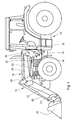
- FIG. 1 is a loader in the form of an agricultural tractor shown.
- the tractor 10 has an attached front loader assembly 12.
- the front loader assembly 12 includes a front loader 13 and a frame assembly or console 16 attached to a vehicle frame 14 of the tractor 12.
- the front loader 13 includes a mast assembly 18 by which the front loader 13 attaches to the console 16 of the front loader assembly 12 is attached to the tractor 10.
- the front loader assembly 12 and the front loader 13 further includes a front loader rocker 20 pivotally mounted to the mast assembly 18, to which a pivotable front loader tool 22 connects.
- the front loader tool 22 is designed, for example, in the form of a loading shovel, wherein the front loader tool 22 could also be designed as a loading fork, gripper, etc.
- the front loader swing 20 is over a hydraulic lift cylinder 24 extending between the mast assembly 18 and the front loader rocker 20, pivotable. Between a connected to the front loader arm 20 link 25 and the mast assembly 18, a steering linkage 26, which serves for parallel guidance of the front loader tool 22 extends.
- the front loader tool 22 is pivotable about a connected to the front loader rocker 20 and the front loader tool 22 pivot linkage 27, as well as a connected to the pivot link 27 and the handlebar 25 hydraulic swing cylinder 28.
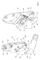
- FIGS. 2 and 2 ' the mast assembly 18 and the console 16 of the front loader assembly 12 is shown enlarged in a perspective side view and in a perspective cross-sectional view.
- the bracket 16 is formed as a solid frame plate 30 and has a receiving area 32 for receiving or coupling the mast assembly 18, and a mounting portion 34 for attaching the bracket 16 to the vehicle frame 14.
- the console 16 is screwed via screw (not shown) to the vehicle frame 14.
- the bracket 16 has at a lower portion of the receiving portion 32 a hook-shaped bearing 36 and at an upper portion of the receiving portion 34 has an opening 38 in the form of a bearing bore.
- the mast assembly 18 has a front side panel 40 and a mirror-inverted opposite rear side panel 42. Between the side plates 40, 42 extends a double-angle arranged frame plate 44, which serves as a reinforcement and support structure. About the frame plate 44th Both side plates 40, 42 are arranged parallel to each other.
- the side plates each have an upper bearing 46, 46 ', a central bearing 48, 48' and a lower bearing 50, 50 ', wherein the upper bearing points 46, 46', the steering linkage 26, to the central bearings 48, 48 ' the front loader rocker 20 and to the lower bearings 50, 50 'of the lifting cylinder 24 are pivotally articulated.
- the side plates 40, 42 in a central region in each case an opening 52, 52 'in the form of a bore, with which the mast assembly 18 is lockable to the opening 38 of the bracket 16, as will be described in detail below.
- a support 53 in the form of a bearing pin, which serves to support the mast assembly 18 on the mounting portion 32 of the console 16 formed bearing 36.
- a locking element 54 is arranged in the form of a connecting bolt which is displaceable in the direction of its longitudinal axis in the openings 52, 52' storable.
- the locking element 54 is rigidly connected via a connecting element 56 in the form of a flat profile or flat steel with an actuating element 58 in the form of a bolt or a round steel or a rod.
- the actuating element 58 is arranged with its longitudinal axis parallel to the locking element 54.
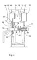
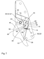
- a locking device 59 is provided which comprises a parallel to the side plates 40, 42 extending and fixed to the frame plate 44 guide plate or retaining plate 60.
- the locking device 59 between the retaining plate 60 and the front side plate 40, a pivotally mounted on a bearing pin 62 locking lever 64, wherein the bearing pin 62 is arranged approximately centrally with respect to the locking lever 64.
- the locking lever 64 is on a first end 66 is connected via a spring 68 with a retaining plate 70, wherein the retaining plate 70 is attached in the form of an angle to the front side wall 40.
- the locking lever 64 has an actuating surface 74 at its second end 72.
- a guide opening 76 is formed on the holding plate 60, through which a free end 78 of the actuating element 58 is guided.
- the actuating element also extends through corresponding passage openings 77, 77 'on the side plates 40, 42, which are designed such that an unimpeded movement of the actuating element 58 is made possible.
- the other end of the actuating element is rigidly connected to the connecting element 56, preferably welded or screwed.
- a threaded bolt 80 is provided with a bolt head 82.
- a spring 84 is tensioned, wherein the spring 84 is formed as a conical or frusto-conical compression spring.
- a shoulder 86 is formed in the context of the locking device 59, which can be brought into engagement with a recess 88 formed on the first end 66 of the locking lever 64.
- the guide opening 76 is formed as a slot, the slot having an upper portion 90 having a first diameter and a lower portion 92 having a smaller second diameter, wherein the first diameter is approximately the normal cross-sectional dimension of the actuator 58 and the second diameter is approximately Cross-sectional dimension of the actuating element 58 corresponds to the shoulder 86, so that in the lower region 92 by the smaller second diameter, a guide of the actuating element 58 at its shoulder 86 or at its free end 78 can take place, as will be described later.
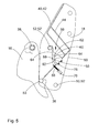
- the actuating member 58 is shown in an unlocked position in which the locking lever 64 is engaged with the shoulder 86 of the actuating element 58 and holds the actuating element 58 against a force applied by the spring 84 actuating force in this position.
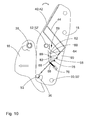
- the actuator 58 is shown in a locked position after the lock lever 64 is actuated (with respect to FIG. 2 rotated clockwise about the bearing pin 62) or the engagement of the locking lever 64 on the shoulder 86 of the actuator 58 released or solved by the locking lever 64 previously made locking so that the actuator 58 by the applied force of the spring 84 was moved. Due to the rigid connection between the actuating element 58 and the locking element 54 produced via the connecting element 56, the latter was displaced accordingly and moved into its locking position, in which it extends through the previously aligned and aligned openings 52, 38 and 52 '. By the force applied by the spring 84 actuating force is the actuating element 58 and thus also the locking element in the locking position according to FIG. 4 held.
- a handle-like projection 94 is provided on the connecting element 56, through which a counter to the force of the spring 84 acting tensile force can be applied or the locking element 54 from the openings 52, 38 and 52 'can be moved out.
Landscapes
- Engineering & Computer Science (AREA)
- Mechanical Engineering (AREA)
- Mining & Mineral Resources (AREA)
- Civil Engineering (AREA)
- General Engineering & Computer Science (AREA)
- Structural Engineering (AREA)
- Shovels (AREA)
- Operation Control Of Excavators (AREA)
- Lock And Its Accessories (AREA)
Applications Claiming Priority (1)
| Application Number | Priority Date | Filing Date | Title |
|---|---|---|---|
| DE102010038469A DE102010038469A1 (de) | 2010-07-27 | 2010-07-27 | Frontladeranordnung |
Publications (3)
| Publication Number | Publication Date |
|---|---|
| EP2412876A2 true EP2412876A2 (fr) | 2012-02-01 |
| EP2412876A3 EP2412876A3 (fr) | 2012-02-22 |
| EP2412876B1 EP2412876B1 (fr) | 2013-05-01 |
Family
ID=44508794
Family Applications (1)
| Application Number | Title | Priority Date | Filing Date |
|---|---|---|---|
| EP11173966.0A Not-in-force EP2412876B1 (fr) | 2010-07-27 | 2011-07-14 | Agencement de chargeur frontal |
Country Status (3)
| Country | Link |
|---|---|
| US (1) | US10337166B2 (fr) |
| EP (1) | EP2412876B1 (fr) |
| DE (1) | DE102010038469A1 (fr) |
Cited By (1)
| Publication number | Priority date | Publication date | Assignee | Title |
|---|---|---|---|---|
| CN104074215A (zh) * | 2014-06-27 | 2014-10-01 | 广西大学 | 一种具有主动变胞功能的多连杆装载机构 |
Families Citing this family (3)
| Publication number | Priority date | Publication date | Assignee | Title |
|---|---|---|---|---|
| US9903095B2 (en) | 2015-01-30 | 2018-02-27 | Caterpillar Inc. | Tool coupler |
| JP6552399B2 (ja) * | 2015-12-07 | 2019-07-31 | 株式会社クボタ | 作業車及びフロントローダ |
| EP4491807A1 (fr) * | 2023-07-13 | 2025-01-15 | Wilhelm Stoll Maschinenfabrik GmbH | Procédé de couplage automatique d'un chargeur frontal avec un véhicule de travail, dispositif de couplage de chargeur frontal automatique, véhicule de travail et système de véhicule de travail |
Citations (1)
| Publication number | Priority date | Publication date | Assignee | Title |
|---|---|---|---|---|
| US20070059147A1 (en) | 2003-09-09 | 2007-03-15 | Tommy Nilsson | Device for attaching a loader to a vehicle |
Family Cites Families (11)
| Publication number | Priority date | Publication date | Assignee | Title |
|---|---|---|---|---|
| DE7430734U (de) * | 1975-03-13 | Baas Technik Gmbh | Sicherheitskupplung | |
| AT374857B (de) * | 1982-12-06 | 1984-06-12 | Hauer Franz | Einrichtung zur loesbaren halterung eines frontladegeraetes an einem fahrzeug |
| US5078569A (en) * | 1990-04-30 | 1992-01-07 | J. I. Case Company | Quick attaching mechanism for a front-end loader |
| DE4327942C1 (de) * | 1993-08-19 | 1995-01-05 | Deere & Co | Vorrichtung zum Festlegen eines Werkzeugs an einem Hubwerk |
| US6142724A (en) * | 1998-03-23 | 2000-11-07 | Kubota Corporation | Front loader attaching structure |
| DE10221941A1 (de) * | 2002-05-17 | 2003-12-04 | Deere & Co | Vorrichtung zum Festlegen eines Werkzeugs an einem Hubwerk |
| JP2004092306A (ja) * | 2002-09-03 | 2004-03-25 | Sanyo Kiki Co Ltd | 作業機の作業部着脱装置 |
| JP4098142B2 (ja) * | 2003-04-14 | 2008-06-11 | 三陽機器株式会社 | 作業機の作業部着脱用台車 |
| US7530779B2 (en) * | 2007-09-28 | 2009-05-12 | Cnh America Llc | Cam-lock mechanism for attachment of implements to prime movers |
| KR100981213B1 (ko) * | 2008-10-22 | 2010-09-10 | 김문수 | 트랙터 작업기용 수동식 연결장치 |
| US8500386B2 (en) * | 2010-04-26 | 2013-08-06 | Deere & Company | Latching system for automatically securing front-mounted loader mast to tractor mounting frame |
-
2010
- 2010-07-27 DE DE102010038469A patent/DE102010038469A1/de not_active Withdrawn
-
2011
- 2011-07-14 EP EP11173966.0A patent/EP2412876B1/fr not_active Not-in-force
- 2011-07-21 US US13/187,799 patent/US10337166B2/en active Active
Patent Citations (1)
| Publication number | Priority date | Publication date | Assignee | Title |
|---|---|---|---|---|
| US20070059147A1 (en) | 2003-09-09 | 2007-03-15 | Tommy Nilsson | Device for attaching a loader to a vehicle |
Cited By (1)
| Publication number | Priority date | Publication date | Assignee | Title |
|---|---|---|---|---|
| CN104074215A (zh) * | 2014-06-27 | 2014-10-01 | 广西大学 | 一种具有主动变胞功能的多连杆装载机构 |
Also Published As
| Publication number | Publication date |
|---|---|
| US20120027551A1 (en) | 2012-02-02 |
| EP2412876B1 (fr) | 2013-05-01 |
| US10337166B2 (en) | 2019-07-02 |
| DE102010038469A1 (de) | 2012-04-05 |
| EP2412876A3 (fr) | 2012-02-22 |
Similar Documents
| Publication | Publication Date | Title |
|---|---|---|
| EP3423313A1 (fr) | Charnière d'ouvrant pour capot avant d'un véhicule, comportant un appui déplaçable pour un déclencheur de levage | |
| DE102009031744A1 (de) | Fahrzeugseitentürenanordnung | |
| DE102009026975A1 (de) | Verriegelungsvorrichtung für einen Teleskopausleger und manueller Bolzenlösemechanismus für diese | |
| EP2982802B1 (fr) | Porte-outil destine a la pose ou la depose d'un outil pour un chargeur, et procede de pose et depose d'un outil | |
| DE102004002213B4 (de) | Fußgängerschutz-Aktuator mit Rückstelleinrichtung | |
| DE10022373A1 (de) | Verriegelungs- und Betätigungseinheit für seitliche Auslegerverriegelung | |
| EP2412876B1 (fr) | Agencement de chargeur frontal | |
| EP2036421B1 (fr) | Dispositif de couplage d'un arbre de transmission avec la prise de force d'un tracteur | |
| EP1362957B1 (fr) | Dispositif pour verrouiller un outil sur an bras élévateur | |
| EP3542963B1 (fr) | Tenseur | |
| EP2829662B1 (fr) | Système de chargeur frontal | |
| DE202008016705U1 (de) | Kraftfahrzeugschloss | |
| EP3745921B1 (fr) | Dispositif de fixation pour un panneau d'un tiroir | |
| EP2918758B1 (fr) | Dispositif de verrouillage | |
| EP2060714A2 (fr) | Crémone-serrure | |
| EP1970508A2 (fr) | Dispositif de blocage d'un élément pivotant d'un véhicule automobile | |
| DE202007013330U1 (de) | Kraftfahrzeugschloß | |
| EP3748109A1 (fr) | Dispositif de verrouillage | |
| EP0942123A1 (fr) | Dispositif pour verrouiller un couvercles notamment pour la capote d'un véhicule | |
| EP3572249B1 (fr) | Attelage de remorque à boulon télécommandé pourvu d'arbre de commande sans application des forces transversales | |
| EP4268562B1 (fr) | Appareil agricole | |
| DE202020105843U1 (de) | Semiautomatische Bolzenverbindung | |
| EP4453327B1 (fr) | Dispositif à changement rapide | |
| EP3851588B1 (fr) | Dispositif de changement rapide | |
| DE102013003672A1 (de) | Fahrzeug mit einem Haubenelement |
Legal Events
| Date | Code | Title | Description |
|---|---|---|---|
| PUAL | Search report despatched |
Free format text: ORIGINAL CODE: 0009013 |
|
| AK | Designated contracting states |
Kind code of ref document: A2 Designated state(s): AL AT BE BG CH CY CZ DE DK EE ES FI FR GB GR HR HU IE IS IT LI LT LU LV MC MK MT NL NO PL PT RO RS SE SI SK SM TR |
|
| AX | Request for extension of the european patent |
Extension state: BA ME |
|
| PUAI | Public reference made under article 153(3) epc to a published international application that has entered the european phase |
Free format text: ORIGINAL CODE: 0009012 |
|
| AK | Designated contracting states |
Kind code of ref document: A3 Designated state(s): AL AT BE BG CH CY CZ DE DK EE ES FI FR GB GR HR HU IE IS IT LI LT LU LV MC MK MT NL NO PL PT RO RS SE SI SK SM TR |
|
| AX | Request for extension of the european patent |
Extension state: BA ME |
|
| RIC1 | Information provided on ipc code assigned before grant |
Ipc: E02F 3/627 20060101AFI20120119BHEP Ipc: E02F 3/36 20060101ALI20120119BHEP |
|
| 17P | Request for examination filed |
Effective date: 20120822 |
|
| GRAP | Despatch of communication of intention to grant a patent |
Free format text: ORIGINAL CODE: EPIDOSNIGR1 |
|
| GRAS | Grant fee paid |
Free format text: ORIGINAL CODE: EPIDOSNIGR3 |
|
| GRAA | (expected) grant |
Free format text: ORIGINAL CODE: 0009210 |
|
| AK | Designated contracting states |
Kind code of ref document: B1 Designated state(s): AL AT BE BG CH CY CZ DE DK EE ES FI FR GB GR HR HU IE IS IT LI LT LU LV MC MK MT NL NO PL PT RO RS SE SI SK SM TR |
|
| REG | Reference to a national code |
Ref country code: GB Ref legal event code: FG4D Free format text: NOT ENGLISH |
|
| REG | Reference to a national code |
Ref country code: AT Ref legal event code: REF Ref document number: 610036 Country of ref document: AT Kind code of ref document: T Effective date: 20130515 Ref country code: CH Ref legal event code: EP |
|
| REG | Reference to a national code |
Ref country code: IE Ref legal event code: FG4D Free format text: LANGUAGE OF EP DOCUMENT: GERMAN |
|
| REG | Reference to a national code |
Ref country code: DE Ref legal event code: R096 Ref document number: 502011000686 Country of ref document: DE Effective date: 20130704 |
|
| REG | Reference to a national code |
Ref country code: NL Ref legal event code: VDEP Effective date: 20130501 |
|
| REG | Reference to a national code |
Ref country code: LT Ref legal event code: MG4D |
|
| PG25 | Lapsed in a contracting state [announced via postgrant information from national office to epo] |
Ref country code: PT Free format text: LAPSE BECAUSE OF FAILURE TO SUBMIT A TRANSLATION OF THE DESCRIPTION OR TO PAY THE FEE WITHIN THE PRESCRIBED TIME-LIMIT Effective date: 20130902 Ref country code: FI Free format text: LAPSE BECAUSE OF FAILURE TO SUBMIT A TRANSLATION OF THE DESCRIPTION OR TO PAY THE FEE WITHIN THE PRESCRIBED TIME-LIMIT Effective date: 20130501 Ref country code: ES Free format text: LAPSE BECAUSE OF FAILURE TO SUBMIT A TRANSLATION OF THE DESCRIPTION OR TO PAY THE FEE WITHIN THE PRESCRIBED TIME-LIMIT Effective date: 20130812 Ref country code: SI Free format text: LAPSE BECAUSE OF FAILURE TO SUBMIT A TRANSLATION OF THE DESCRIPTION OR TO PAY THE FEE WITHIN THE PRESCRIBED TIME-LIMIT Effective date: 20130501 Ref country code: NO Free format text: LAPSE BECAUSE OF FAILURE TO SUBMIT A TRANSLATION OF THE DESCRIPTION OR TO PAY THE FEE WITHIN THE PRESCRIBED TIME-LIMIT Effective date: 20130801 Ref country code: GR Free format text: LAPSE BECAUSE OF FAILURE TO SUBMIT A TRANSLATION OF THE DESCRIPTION OR TO PAY THE FEE WITHIN THE PRESCRIBED TIME-LIMIT Effective date: 20130802 Ref country code: LT Free format text: LAPSE BECAUSE OF FAILURE TO SUBMIT A TRANSLATION OF THE DESCRIPTION OR TO PAY THE FEE WITHIN THE PRESCRIBED TIME-LIMIT Effective date: 20130501 Ref country code: SE Free format text: LAPSE BECAUSE OF FAILURE TO SUBMIT A TRANSLATION OF THE DESCRIPTION OR TO PAY THE FEE WITHIN THE PRESCRIBED TIME-LIMIT Effective date: 20130501 Ref country code: IS Free format text: LAPSE BECAUSE OF FAILURE TO SUBMIT A TRANSLATION OF THE DESCRIPTION OR TO PAY THE FEE WITHIN THE PRESCRIBED TIME-LIMIT Effective date: 20130901 |
|
| PG25 | Lapsed in a contracting state [announced via postgrant information from national office to epo] |
Ref country code: HR Free format text: LAPSE BECAUSE OF FAILURE TO SUBMIT A TRANSLATION OF THE DESCRIPTION OR TO PAY THE FEE WITHIN THE PRESCRIBED TIME-LIMIT Effective date: 20130501 Ref country code: PL Free format text: LAPSE BECAUSE OF FAILURE TO SUBMIT A TRANSLATION OF THE DESCRIPTION OR TO PAY THE FEE WITHIN THE PRESCRIBED TIME-LIMIT Effective date: 20130501 Ref country code: RS Free format text: LAPSE BECAUSE OF FAILURE TO SUBMIT A TRANSLATION OF THE DESCRIPTION OR TO PAY THE FEE WITHIN THE PRESCRIBED TIME-LIMIT Effective date: 20130501 Ref country code: BG Free format text: LAPSE BECAUSE OF FAILURE TO SUBMIT A TRANSLATION OF THE DESCRIPTION OR TO PAY THE FEE WITHIN THE PRESCRIBED TIME-LIMIT Effective date: 20130801 Ref country code: CY Free format text: LAPSE BECAUSE OF FAILURE TO SUBMIT A TRANSLATION OF THE DESCRIPTION OR TO PAY THE FEE WITHIN THE PRESCRIBED TIME-LIMIT Effective date: 20130501 |
|
| PG25 | Lapsed in a contracting state [announced via postgrant information from national office to epo] |
Ref country code: LV Free format text: LAPSE BECAUSE OF FAILURE TO SUBMIT A TRANSLATION OF THE DESCRIPTION OR TO PAY THE FEE WITHIN THE PRESCRIBED TIME-LIMIT Effective date: 20130501 |
|
| BERE | Be: lapsed |
Owner name: DEERE & CY Effective date: 20130731 |
|
| PG25 | Lapsed in a contracting state [announced via postgrant information from national office to epo] |
Ref country code: CZ Free format text: LAPSE BECAUSE OF FAILURE TO SUBMIT A TRANSLATION OF THE DESCRIPTION OR TO PAY THE FEE WITHIN THE PRESCRIBED TIME-LIMIT Effective date: 20130501 Ref country code: SK Free format text: LAPSE BECAUSE OF FAILURE TO SUBMIT A TRANSLATION OF THE DESCRIPTION OR TO PAY THE FEE WITHIN THE PRESCRIBED TIME-LIMIT Effective date: 20130501 Ref country code: EE Free format text: LAPSE BECAUSE OF FAILURE TO SUBMIT A TRANSLATION OF THE DESCRIPTION OR TO PAY THE FEE WITHIN THE PRESCRIBED TIME-LIMIT Effective date: 20130501 Ref country code: DK Free format text: LAPSE BECAUSE OF FAILURE TO SUBMIT A TRANSLATION OF THE DESCRIPTION OR TO PAY THE FEE WITHIN THE PRESCRIBED TIME-LIMIT Effective date: 20130501 |
|
| PG25 | Lapsed in a contracting state [announced via postgrant information from national office to epo] |
Ref country code: RO Free format text: LAPSE BECAUSE OF FAILURE TO SUBMIT A TRANSLATION OF THE DESCRIPTION OR TO PAY THE FEE WITHIN THE PRESCRIBED TIME-LIMIT Effective date: 20130501 Ref country code: MC Free format text: LAPSE BECAUSE OF FAILURE TO SUBMIT A TRANSLATION OF THE DESCRIPTION OR TO PAY THE FEE WITHIN THE PRESCRIBED TIME-LIMIT Effective date: 20130501 Ref country code: IT Free format text: LAPSE BECAUSE OF FAILURE TO SUBMIT A TRANSLATION OF THE DESCRIPTION OR TO PAY THE FEE WITHIN THE PRESCRIBED TIME-LIMIT Effective date: 20130501 Ref country code: NL Free format text: LAPSE BECAUSE OF FAILURE TO SUBMIT A TRANSLATION OF THE DESCRIPTION OR TO PAY THE FEE WITHIN THE PRESCRIBED TIME-LIMIT Effective date: 20130501 |
|
| PLBE | No opposition filed within time limit |
Free format text: ORIGINAL CODE: 0009261 |
|
| STAA | Information on the status of an ep patent application or granted ep patent |
Free format text: STATUS: NO OPPOSITION FILED WITHIN TIME LIMIT |
|
| 26N | No opposition filed |
Effective date: 20140204 |
|
| REG | Reference to a national code |
Ref country code: IE Ref legal event code: MM4A |
|
| PG25 | Lapsed in a contracting state [announced via postgrant information from national office to epo] |
Ref country code: BE Free format text: LAPSE BECAUSE OF NON-PAYMENT OF DUE FEES Effective date: 20130731 |
|
| REG | Reference to a national code |
Ref country code: DE Ref legal event code: R097 Ref document number: 502011000686 Country of ref document: DE Effective date: 20140204 |
|
| PG25 | Lapsed in a contracting state [announced via postgrant information from national office to epo] |
Ref country code: IE Free format text: LAPSE BECAUSE OF NON-PAYMENT OF DUE FEES Effective date: 20130714 |
|
| PGFP | Annual fee paid to national office [announced via postgrant information from national office to epo] |
Ref country code: DE Payment date: 20140619 Year of fee payment: 4 |
|
| PGFP | Annual fee paid to national office [announced via postgrant information from national office to epo] |
Ref country code: FR Payment date: 20140717 Year of fee payment: 4 |
|
| REG | Reference to a national code |
Ref country code: CH Ref legal event code: PL |
|
| PG25 | Lapsed in a contracting state [announced via postgrant information from national office to epo] |
Ref country code: CH Free format text: LAPSE BECAUSE OF NON-PAYMENT OF DUE FEES Effective date: 20140731 Ref country code: LI Free format text: LAPSE BECAUSE OF NON-PAYMENT OF DUE FEES Effective date: 20140731 |
|
| PG25 | Lapsed in a contracting state [announced via postgrant information from national office to epo] |
Ref country code: SM Free format text: LAPSE BECAUSE OF FAILURE TO SUBMIT A TRANSLATION OF THE DESCRIPTION OR TO PAY THE FEE WITHIN THE PRESCRIBED TIME-LIMIT Effective date: 20130501 |
|
| PG25 | Lapsed in a contracting state [announced via postgrant information from national office to epo] |
Ref country code: TR Free format text: LAPSE BECAUSE OF FAILURE TO SUBMIT A TRANSLATION OF THE DESCRIPTION OR TO PAY THE FEE WITHIN THE PRESCRIBED TIME-LIMIT Effective date: 20130501 Ref country code: MT Free format text: LAPSE BECAUSE OF FAILURE TO SUBMIT A TRANSLATION OF THE DESCRIPTION OR TO PAY THE FEE WITHIN THE PRESCRIBED TIME-LIMIT Effective date: 20130501 |
|
| PG25 | Lapsed in a contracting state [announced via postgrant information from national office to epo] |
Ref country code: MK Free format text: LAPSE BECAUSE OF FAILURE TO SUBMIT A TRANSLATION OF THE DESCRIPTION OR TO PAY THE FEE WITHIN THE PRESCRIBED TIME-LIMIT Effective date: 20130501 Ref country code: LU Free format text: LAPSE BECAUSE OF NON-PAYMENT OF DUE FEES Effective date: 20130714 Ref country code: HU Free format text: LAPSE BECAUSE OF FAILURE TO SUBMIT A TRANSLATION OF THE DESCRIPTION OR TO PAY THE FEE WITHIN THE PRESCRIBED TIME-LIMIT; INVALID AB INITIO Effective date: 20110714 |
|
| REG | Reference to a national code |
Ref country code: DE Ref legal event code: R119 Ref document number: 502011000686 Country of ref document: DE |
|
| GBPC | Gb: european patent ceased through non-payment of renewal fee |
Effective date: 20150714 |
|
| PG25 | Lapsed in a contracting state [announced via postgrant information from national office to epo] |
Ref country code: GB Free format text: LAPSE BECAUSE OF NON-PAYMENT OF DUE FEES Effective date: 20150714 Ref country code: DE Free format text: LAPSE BECAUSE OF NON-PAYMENT OF DUE FEES Effective date: 20160202 |
|
| REG | Reference to a national code |
Ref country code: FR Ref legal event code: ST Effective date: 20160331 |
|
| PG25 | Lapsed in a contracting state [announced via postgrant information from national office to epo] |
Ref country code: FR Free format text: LAPSE BECAUSE OF NON-PAYMENT OF DUE FEES Effective date: 20150731 |
|
| REG | Reference to a national code |
Ref country code: AT Ref legal event code: MM01 Ref document number: 610036 Country of ref document: AT Kind code of ref document: T Effective date: 20160714 |
|
| PG25 | Lapsed in a contracting state [announced via postgrant information from national office to epo] |
Ref country code: AT Free format text: LAPSE BECAUSE OF NON-PAYMENT OF DUE FEES Effective date: 20160714 |
|
| PG25 | Lapsed in a contracting state [announced via postgrant information from national office to epo] |
Ref country code: AL Free format text: LAPSE BECAUSE OF FAILURE TO SUBMIT A TRANSLATION OF THE DESCRIPTION OR TO PAY THE FEE WITHIN THE PRESCRIBED TIME-LIMIT Effective date: 20130501 |