EP2412949A2 - Appareil pour refroidissement de moteur - Google Patents
Appareil pour refroidissement de moteur Download PDFInfo
- Publication number
- EP2412949A2 EP2412949A2 EP11175881A EP11175881A EP2412949A2 EP 2412949 A2 EP2412949 A2 EP 2412949A2 EP 11175881 A EP11175881 A EP 11175881A EP 11175881 A EP11175881 A EP 11175881A EP 2412949 A2 EP2412949 A2 EP 2412949A2
- Authority
- EP
- European Patent Office
- Prior art keywords
- engine
- cooling water
- rotation speed
- flow passage
- bypass
- Prior art date
- Legal status (The legal status is an assumption and is not a legal conclusion. Google has not performed a legal analysis and makes no representation as to the accuracy of the status listed.)
- Withdrawn
Links
- 238000001816 cooling Methods 0.000 title claims abstract description 14
- 239000000498 cooling water Substances 0.000 claims abstract description 81
- XLYOFNOQVPJJNP-UHFFFAOYSA-N water Substances O XLYOFNOQVPJJNP-UHFFFAOYSA-N 0.000 claims abstract description 18
- 238000011144 upstream manufacturing Methods 0.000 claims description 12
- 230000007423 decrease Effects 0.000 description 6
- 230000007547 defect Effects 0.000 description 1
- 238000010586 diagram Methods 0.000 description 1
- 239000000446 fuel Substances 0.000 description 1
- 238000000034 method Methods 0.000 description 1
Images

Classifications
-
- F—MECHANICAL ENGINEERING; LIGHTING; HEATING; WEAPONS; BLASTING
- F01—MACHINES OR ENGINES IN GENERAL; ENGINE PLANTS IN GENERAL; STEAM ENGINES
- F01P—COOLING OF MACHINES OR ENGINES IN GENERAL; COOLING OF INTERNAL-COMBUSTION ENGINES
- F01P7/00—Controlling of coolant flow
- F01P7/14—Controlling of coolant flow the coolant being liquid
- F01P7/16—Controlling of coolant flow the coolant being liquid by thermostatic control
- F01P7/165—Controlling of coolant flow the coolant being liquid by thermostatic control characterised by systems with two or more loops
-
- F—MECHANICAL ENGINEERING; LIGHTING; HEATING; WEAPONS; BLASTING
- F01—MACHINES OR ENGINES IN GENERAL; ENGINE PLANTS IN GENERAL; STEAM ENGINES
- F01P—COOLING OF MACHINES OR ENGINES IN GENERAL; COOLING OF INTERNAL-COMBUSTION ENGINES
- F01P7/00—Controlling of coolant flow
- F01P7/14—Controlling of coolant flow the coolant being liquid
- F01P7/16—Controlling of coolant flow the coolant being liquid by thermostatic control
- F01P7/167—Controlling of coolant flow the coolant being liquid by thermostatic control by adjusting the pre-set temperature according to engine parameters, e.g. engine load, engine speed
-
- F—MECHANICAL ENGINEERING; LIGHTING; HEATING; WEAPONS; BLASTING
- F01—MACHINES OR ENGINES IN GENERAL; ENGINE PLANTS IN GENERAL; STEAM ENGINES
- F01P—COOLING OF MACHINES OR ENGINES IN GENERAL; COOLING OF INTERNAL-COMBUSTION ENGINES
- F01P2025/00—Measuring
- F01P2025/60—Operating parameters
- F01P2025/64—Number of revolutions
-
- F—MECHANICAL ENGINEERING; LIGHTING; HEATING; WEAPONS; BLASTING
- F01—MACHINES OR ENGINES IN GENERAL; ENGINE PLANTS IN GENERAL; STEAM ENGINES
- F01P—COOLING OF MACHINES OR ENGINES IN GENERAL; COOLING OF INTERNAL-COMBUSTION ENGINES
- F01P2060/00—Cooling circuits using auxiliaries
- F01P2060/08—Cabin heater
Definitions
- the present invention relates to an engine cooling apparatus that achieves an increase in a circulation flow rate of cooling water in a low/medium rotation region while suppressing cavitation in a high rotation region.
- a valve is provided in one of the two bypass circuits, and by opening the valve when an engine rotation speed is high in order to reduce a flow passage resistance, an attempt is made to prevent cavitation.
- a first bypass passage (7) and a second bypass passage (10) are connected in parallel so as to bypass a radiator (2), and a solenoid control valve (11) is disposed at a midway point on the second bypass passage (10).
- a valve opening of the solenoid control valve (11) is controlled on the basis of an engine rotation speed detected by an engine rotation speed sensor (12). Meanwhile, a flow rate of cooling water flowing through the first bypass passage (7) is controlled by a thermostat (4).
- the opening of the solenoid control valve (11) is increased when the engine is in a high rotation region, thereby increasing the flow rate of the cooling water flowing through the second bypass passage (10). Further, the opening of the solenoid control valve (11) is reduced when the engine is in an intermediate rotation region, thereby reducing the flow rate of the cooling water flowing through the second bypass passage (10).
- a cooling capability can be secured in the intermediate rotation region of the engine, while in the high rotation region of the engine, a reduction in flow resistance is achieved by increasing the cooling water flow rate, enabling an increase in a water pressure of the cooling circuit.
- an internal pressure of a suction side flow passage of the water pump typically decreases as a discharge flow rate of the water pump increases. As the pressure decreases, cavitation becomes more likely to occur, and therefore the discharge flow rate of the water pump should not be increased more than necessary.
- the present invention has been designed in consideration of these problems, and an object thereof is to provide an engine cooling apparatus that is capable of suppressing cavitation in a high rotation region of an engine while maintaining a cooling capability in an intermediate rotation region of the engine.
- a first aspect of the present invention provides an engine cooling apparatus that solves the problems described above by including: a main cooling water circuit that circulates cooling water between an engine and a radiator; a branch portion provided in the main cooling water circuit between the engine and the radiator; a thermostat provided in the main cooling water circuit between the radiator and the engine on a side where the branch portion is not provided; temperature detecting means for detecting a temperature of the cooling water in the main cooling water circuit; a first bypass flow passage provided between the branch portion and the thermostat; a second bypass flow passage that connects the engine to the branch portion and connects the thermostat to the engine; a control valve provided in the second bypass flow passage; a bypass convergence portion between the main cooling water circuit and the second bypass flow passage; a water pump that is provided between a downstream side of the thermostat and an upstream side of the engine and activated by driving the engine; valve opening control means for controlling an opening of the control valve; and engine rotation speed detecting means for detecting a rotation speed of the engine, wherein, when the temperature of the
- a second aspect according to claim 1 solves the problems described above by providing an engine cooling apparatus that performs control for reducing the predetermined rotation speed as the temperature of the cooling water detected by the temperature detecting means increases.
- the control valve in the second bypass flow passage when the rotation speed of the engine falls to or below the predetermined rotation speed, the control valve in the second bypass flow passage is set in a fully open state, whereby the second bypass flow passage is set in the circulation state in which the cooling water flows. Accordingly, the flow resistance of the cooling water circuit decreases, leading to an increase in the amount of cooling water circulating through the engine, and as a result, a sufficient cooling performance can be secured and knocking can be suppressed.
- the control valve is controlled gradually in the fully closed direction from the fully open state in accordance with the increase in the rotation speed, and therefore, in contrast with a case where the control valve is set only in the fully open state and the fully closed state, the flow rate of the cooling water supplied to the engine is appropriate for the rotation speed of the engine.
- unnecessary work by the water pump can be eliminated.
- the first bypass flow passage is not modified from that of the related art, and therefore travel remains possible even if a defect occurs in the second bypass flow passage, albeit with a slightly poorer fuel efficiency.
- the predetermined rotation speed for controlling the opening of the control valve is controlled to be steadily lower as the cooling water temperature rises.
- Lowering the predetermined rotation speed means lowering the rotation speed of the engine at which control of the control valve in the fully closed direction from the fully open state begins.
- a rotation speed range in which cavitation occurs tends to shift to a low rotation side, and therefore, by lowering the predetermined rotation speed, cavitation can be suppressed.
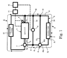
- the present embodiment is a circuit for circulating cooling water between an engine 1 and a radiator 2, which is mainly constituted by a main cooling water circuit A, a first bypass flow passage 53, and a second bypass flow passage 54.
- a heater circuit B having a flow passage that passes through an engine 1 and a heater core 12 provided in the flow passage is provided in addition to the main cooling water circuit A.
- Fig. 1 shows the cooling water circuit according to an embodiment of the present invention.
- a side of internal components of the cooling water circuit such as the radiator 2 and a thermostat 4 on which the cooling water flows into the components will be referred to as an upstream side and indicated by affixing a reference symbol "U" to the respective components
- a side on which the cooling water flows out of the components will be referred to as a downstream side and indicated by affixing a reference symbol "L” to the respective components (see Fig. 1 ).
- the main cooling water circuit A is constituted by the engine 1, the radiator 2, and a main flow passage 5.
- the main flow passage 5 is constituted by a flow passage 51 that connects a downstream side 1L of the engine 1 to an upstream side 2U of the radiator 2, and a flow passage 52 that connects a downstream side 2L of the radiator 2 to an upstream side 1U of the engine 1.
- the thermostat 4 is provided at a midway point on the flow passage 52 connecting the downstream side 2L of the radiator 2 to the upstream side 1U of the engine 1.
- a water pump 7 is provided between a downstream side 4L of the thermostat 4 and the upstream side 1U of the engine 1, and temperature detecting means 9 for detecting a temperature of the cooling water is provided in the main cooling water circuit A.
- bypass branch portions 31, 32 are provided at midway points on the flow passage 51 connecting the downstream side 1L of the engine 1 to the radiator upstream side 2U.
- the first bypass flow passage 53 is provided between one of the bypass branch portions 31 and an upstream side 4U of the thermostat 4 so as to connect the bypass branch portion 31 and the upstream side 4U of the thermostat 4.
- a bypass convergence portion 8 is provided at a midway point on the flow passage 52 connecting the downstream side 2L of the radiator 2 to the upstream side 1U of the engine 1 and between the downstream side 4L of the thermostat 4 and an upstream side 7U of the water pump 7.
- the second bypass flow passage 54 is provided between the other bypass branch portion 32 and the bypass convergence portion 8 so as to connect the other bypass branch portion 32 and the bypass convergence portion 8.
- Valve opening control means 10 and engine rotation speed detecting means 11 are also provided in the main cooling water circuit A, and a control valve 6 that controls a flow rate of the cooling water flowing through the second bypass flow passage 54 in accordance with the valve opening control means 10 is provided at a midway point on the second bypass flow passage 54.
- the thermostat 4 is a temperature-sensitive operating valve, and has a function for varying a flow rate ratio between the cooling water flowing through the first bypass flow passage 53 and the cooling water flowing through the radiator 2 in accordance with the temperature of cooling water that flows in from the first bypass flow passage 53, cooling water that flows in through the flow passage 52 after passing through the radiator 2, or cooling water generated when the cooling water that flows in from the first bypass flow passage 53 and the cooling water that flows in from flow passage 52 intermix.
- bypass branch portion 31 is shown to be closer to the radiator 2 than the bypass branch portion 32, but the bypass branch portion 31 and the bypass branch portion 32 are not limited to this positional relationship, and the bypass branch portion 32 may be disposed closer to the radiator 2 than the bypass branch portion 31.
- number of branch portions is not limited to two, and the first bypass flow passage 53 may be bifurcated from the second bypass flow passage 54 by a single branch portion.
- the control performed by the control valve 6 in the second bypass flow passage 54 can be executed in an identical manner to this embodiment even when the bypass branch portion 31 and the thermostat 4 are disposed oppositely, and therefore the bypass branch portion 31 and the thermostat 4 may be disposed oppositely.
- Fig. 2 is a graph showing characteristics of an embodiment of the present invention.
- An abscissa of the graph shows the engine rotation speed, and an ordinate shows a circulation flow rate of the cooling water through the engine.
- a vertical axis shown in a central location of the abscissa is a reference line indicating a predetermined rotation speed of the engine.
- the control valve 6 is controlled to a fully open state by the valve opening control means 10, and therefore the second bypass flow passage 54 enters a circulation state in which the cooling water flows.
- a flow resistance of the cooling water circuit decreases, leading to an increase in a discharge flow rate of the water pump 7 and a corresponding increase in the amount of cooling water supplied to the engine 1.
- the flow rate of the cooling water to be supplied to the engine 1 is determined in accordance with engine properties such as a knocking capacity of the engine 1. Specifications such as a diameter and a length of the second bypass flow passage 54 are set so that this flow rate is achieved.
- the control valve 6 is controlled by the valve opening control means 10 to shift gradually in the fully closed direction from the fully open state as the rotation speed of the engine 1 increases.
- the flow rate of the cooling water flowing through the second bypass flow passage 54 can be adjusted in accordance with the variation in the opening of the control valve 6.
- the rotation speed (the predetermined rotation speed) of the engine 1 at which control of the valve opening of the control valve 6 in the fully closed direction from the fully open state begins is modified to a low rotation side. In so doing, cavitation can be suppressed even in a high temperature state.
Landscapes
- Engineering & Computer Science (AREA)
- Chemical & Material Sciences (AREA)
- Combustion & Propulsion (AREA)
- Mechanical Engineering (AREA)
- General Engineering & Computer Science (AREA)
- Temperature-Responsive Valves (AREA)
- Structures Of Non-Positive Displacement Pumps (AREA)
- Motor Or Generator Cooling System (AREA)
Applications Claiming Priority (1)
| Application Number | Priority Date | Filing Date | Title |
|---|---|---|---|
| JP2010172971A JP2012031800A (ja) | 2010-07-30 | 2010-07-30 | エンジンの冷却装置 |
Publications (2)
| Publication Number | Publication Date |
|---|---|
| EP2412949A2 true EP2412949A2 (fr) | 2012-02-01 |
| EP2412949A3 EP2412949A3 (fr) | 2013-03-06 |
Family
ID=44514536
Family Applications (1)
| Application Number | Title | Priority Date | Filing Date |
|---|---|---|---|
| EP11175881A Withdrawn EP2412949A3 (fr) | 2010-07-30 | 2011-07-28 | Appareil pour refroidissement de moteur |
Country Status (4)
| Country | Link |
|---|---|
| US (1) | US20120024243A1 (fr) |
| EP (1) | EP2412949A3 (fr) |
| JP (1) | JP2012031800A (fr) |
| CN (1) | CN102345502A (fr) |
Families Citing this family (8)
| Publication number | Priority date | Publication date | Assignee | Title |
|---|---|---|---|---|
| US9341105B2 (en) * | 2012-03-30 | 2016-05-17 | Ford Global Technologies, Llc | Engine cooling system control |
| JP5623474B2 (ja) * | 2012-08-13 | 2014-11-12 | トヨタ自動車株式会社 | 冷却水制御装置 |
| WO2016016813A1 (fr) * | 2014-08-01 | 2016-02-04 | Piaggio & C. S.P.A. | Moteur a combustion interne a refroidissement par eau |
| JP6306529B2 (ja) * | 2015-03-06 | 2018-04-04 | 日立オートモティブシステムズ株式会社 | 車両用内燃機関の冷却装置及び制御方法 |
| JP6330768B2 (ja) * | 2015-09-16 | 2018-05-30 | トヨタ自動車株式会社 | エンジン冷却装置 |
| WO2021038776A1 (fr) * | 2019-08-29 | 2021-03-04 | 株式会社ミクニ | Dispositif de refroidissement de moteur |
| CN112177752B (zh) * | 2020-08-21 | 2021-07-06 | 东风汽车集团有限公司 | 一种发动机热管理模块的控制方法和控制系统 |
| CN112443385A (zh) * | 2020-12-15 | 2021-03-05 | 广西玉柴机器股份有限公司 | 发动机的冷却系统 |
Citations (1)
| Publication number | Priority date | Publication date | Assignee | Title |
|---|---|---|---|---|
| JP2007100659A (ja) | 2005-10-07 | 2007-04-19 | Calsonic Kansei Corp | エンジン冷却システム |
Family Cites Families (2)
| Publication number | Priority date | Publication date | Assignee | Title |
|---|---|---|---|---|
| US6725812B1 (en) * | 2000-12-01 | 2004-04-27 | Borgwarner, Inc. | Water pump driven by viscous coupling |
| JP2005083225A (ja) * | 2003-09-05 | 2005-03-31 | Calsonic Kansei Corp | トランスミッション油温制御装置 |
-
2010
- 2010-07-30 JP JP2010172971A patent/JP2012031800A/ja active Pending
-
2011
- 2011-07-25 US US13/137,175 patent/US20120024243A1/en not_active Abandoned
- 2011-07-28 EP EP11175881A patent/EP2412949A3/fr not_active Withdrawn
- 2011-07-29 CN CN2011102155639A patent/CN102345502A/zh active Pending
Patent Citations (1)
| Publication number | Priority date | Publication date | Assignee | Title |
|---|---|---|---|---|
| JP2007100659A (ja) | 2005-10-07 | 2007-04-19 | Calsonic Kansei Corp | エンジン冷却システム |
Also Published As
| Publication number | Publication date |
|---|---|
| CN102345502A (zh) | 2012-02-08 |
| EP2412949A3 (fr) | 2013-03-06 |
| JP2012031800A (ja) | 2012-02-16 |
| US20120024243A1 (en) | 2012-02-02 |
Similar Documents
| Publication | Publication Date | Title |
|---|---|---|
| EP2412949A2 (fr) | Appareil pour refroidissement de moteur | |
| CN109631376B (zh) | 螺杆式冷水机组及其控制方法、系统 | |
| US8342141B2 (en) | Engine cooling system | |
| US9982587B2 (en) | Cooling system for engine | |
| CN106461062B (zh) | 车辆驱动装置 | |
| JP5329078B2 (ja) | 空気調和装置に用いられる高圧シェル圧縮機の均油システム | |
| JP2000315513A (ja) | 燃料電池自動車用ラジエータシステム | |
| EP1674688A1 (fr) | Système de refroidissement pour un moteur à combustion interne | |
| JP6011495B2 (ja) | 冷却水制御装置 | |
| JP5267159B2 (ja) | 潤滑油の温度制御システム | |
| JP2011099400A (ja) | 車両の冷却装置 | |
| JP6528673B2 (ja) | 油圧式作業機械の作動油温度調節装置 | |
| KR20190130882A (ko) | 차량용 냉각수온센서 고장 진단방법 | |
| WO2018003211A1 (fr) | Unité de compresseur d'air | |
| CN105143670A (zh) | 流体供给装置 | |
| US20260034917A1 (en) | Vehicle cooling system and vehicle | |
| CN117325721A (zh) | 用于具有燃料电池的车辆的冷却系统 | |
| WO2010130319A1 (fr) | Système d'alimentation en fluide et procédé d'actionnement d'un système d'alimentation en fluide | |
| CN113266756B (zh) | 一种机组停机再循环冷却系统及方法 | |
| JP5267654B2 (ja) | エンジンの冷却装置 | |
| CN204961050U (zh) | 发动机冷却系统及车辆 | |
| CN111952628B (zh) | 一种氢能源汽车燃料电池热管理系统 | |
| US11598230B2 (en) | Fluid circuit and a process for controlling a flow of fluid supplied to at least one equipment | |
| JP7084279B2 (ja) | エンジン冷却装置 | |
| CN207527008U (zh) | 变速器冷却系统 |
Legal Events
| Date | Code | Title | Description |
|---|---|---|---|
| AK | Designated contracting states |
Kind code of ref document: A2 Designated state(s): AL AT BE BG CH CY CZ DE DK EE ES FI FR GB GR HR HU IE IS IT LI LT LU LV MC MK MT NL NO PL PT RO RS SE SI SK SM TR |
|
| AX | Request for extension of the european patent |
Extension state: BA ME |
|
| PUAI | Public reference made under article 153(3) epc to a published international application that has entered the european phase |
Free format text: ORIGINAL CODE: 0009012 |
|
| PUAL | Search report despatched |
Free format text: ORIGINAL CODE: 0009013 |
|
| AK | Designated contracting states |
Kind code of ref document: A3 Designated state(s): AL AT BE BG CH CY CZ DE DK EE ES FI FR GB GR HR HU IE IS IT LI LT LU LV MC MK MT NL NO PL PT RO RS SE SI SK SM TR |
|
| AX | Request for extension of the european patent |
Extension state: BA ME |
|
| RIC1 | Information provided on ipc code assigned before grant |
Ipc: F01P 7/14 20060101AFI20130130BHEP Ipc: F01P 7/16 20060101ALI20130130BHEP |
|
| STAA | Information on the status of an ep patent application or granted ep patent |
Free format text: STATUS: THE APPLICATION IS DEEMED TO BE WITHDRAWN |
|
| 18D | Application deemed to be withdrawn |
Effective date: 20130907 |