EP2416083B1 - System und verfahren zum erwärmen eines fluids und system zur steuerung des erwärmens eines fluids, steuervorrichtung und steuerverfahren - Google Patents
System und verfahren zum erwärmen eines fluids und system zur steuerung des erwärmens eines fluids, steuervorrichtung und steuerverfahren Download PDFInfo
- Publication number
- EP2416083B1 EP2416083B1 EP09842964.0A EP09842964A EP2416083B1 EP 2416083 B1 EP2416083 B1 EP 2416083B1 EP 09842964 A EP09842964 A EP 09842964A EP 2416083 B1 EP2416083 B1 EP 2416083B1
- Authority
- EP
- European Patent Office
- Prior art keywords
- heaters
- heating capacity
- fluid
- capacity
- heating
- Prior art date
- Legal status (The legal status is an assumption and is not a legal conclusion. Google has not performed a legal analysis and makes no representation as to the accuracy of the status listed.)
- Not-in-force
Links
Images



Classifications
-
- F—MECHANICAL ENGINEERING; LIGHTING; HEATING; WEAPONS; BLASTING
- F24—HEATING; RANGES; VENTILATING
- F24D—DOMESTIC- OR SPACE-HEATING SYSTEMS, e.g. CENTRAL HEATING SYSTEMS; DOMESTIC HOT-WATER SUPPLY SYSTEMS; ELEMENTS OR COMPONENTS THEREFOR
- F24D11/00—Central heating systems using heat accumulated in storage masses
- F24D11/02—Central heating systems using heat accumulated in storage masses using heat pumps
- F24D11/0214—Central heating systems using heat accumulated in storage masses using heat pumps water heating system
-
- F—MECHANICAL ENGINEERING; LIGHTING; HEATING; WEAPONS; BLASTING
- F24—HEATING; RANGES; VENTILATING
- F24D—DOMESTIC- OR SPACE-HEATING SYSTEMS, e.g. CENTRAL HEATING SYSTEMS; DOMESTIC HOT-WATER SUPPLY SYSTEMS; ELEMENTS OR COMPONENTS THEREFOR
- F24D17/00—Domestic hot-water supply systems
- F24D17/02—Domestic hot-water supply systems using heat pumps
-
- F—MECHANICAL ENGINEERING; LIGHTING; HEATING; WEAPONS; BLASTING
- F24—HEATING; RANGES; VENTILATING
- F24D—DOMESTIC- OR SPACE-HEATING SYSTEMS, e.g. CENTRAL HEATING SYSTEMS; DOMESTIC HOT-WATER SUPPLY SYSTEMS; ELEMENTS OR COMPONENTS THEREFOR
- F24D19/00—Details
- F24D19/10—Arrangement or mounting of control or safety devices
- F24D19/1006—Arrangement or mounting of control or safety devices for water heating systems
- F24D19/1066—Arrangement or mounting of control or safety devices for water heating systems for the combination of central heating and domestic hot water
- F24D19/1072—Arrangement or mounting of control or safety devices for water heating systems for the combination of central heating and domestic hot water the system uses a heat pump
-
- F—MECHANICAL ENGINEERING; LIGHTING; HEATING; WEAPONS; BLASTING
- F24—HEATING; RANGES; VENTILATING
- F24H—FLUID HEATERS, e.g. WATER OR AIR HEATERS, HAVING HEAT-GENERATING MEANS, e.g. HEAT PUMPS, IN GENERAL
- F24H15/00—Control of fluid heaters
- F24H15/10—Control of fluid heaters characterised by the purpose of the control
- F24H15/144—Measuring or calculating energy consumption
-
- F—MECHANICAL ENGINEERING; LIGHTING; HEATING; WEAPONS; BLASTING
- F24—HEATING; RANGES; VENTILATING
- F24H—FLUID HEATERS, e.g. WATER OR AIR HEATERS, HAVING HEAT-GENERATING MEANS, e.g. HEAT PUMPS, IN GENERAL
- F24H15/00—Control of fluid heaters
- F24H15/10—Control of fluid heaters characterised by the purpose of the control
- F24H15/156—Reducing the quantity of energy consumed; Increasing efficiency
-
- F—MECHANICAL ENGINEERING; LIGHTING; HEATING; WEAPONS; BLASTING
- F24—HEATING; RANGES; VENTILATING
- F24H—FLUID HEATERS, e.g. WATER OR AIR HEATERS, HAVING HEAT-GENERATING MEANS, e.g. HEAT PUMPS, IN GENERAL
- F24H15/00—Control of fluid heaters
- F24H15/20—Control of fluid heaters characterised by control inputs
- F24H15/258—Outdoor temperature
-
- F—MECHANICAL ENGINEERING; LIGHTING; HEATING; WEAPONS; BLASTING
- F24—HEATING; RANGES; VENTILATING
- F24H—FLUID HEATERS, e.g. WATER OR AIR HEATERS, HAVING HEAT-GENERATING MEANS, e.g. HEAT PUMPS, IN GENERAL
- F24H15/00—Control of fluid heaters
- F24H15/20—Control of fluid heaters characterised by control inputs
- F24H15/269—Time, e.g. hour or date
-
- F—MECHANICAL ENGINEERING; LIGHTING; HEATING; WEAPONS; BLASTING
- F24—HEATING; RANGES; VENTILATING
- F24H—FLUID HEATERS, e.g. WATER OR AIR HEATERS, HAVING HEAT-GENERATING MEANS, e.g. HEAT PUMPS, IN GENERAL
- F24H15/00—Control of fluid heaters
- F24H15/20—Control of fluid heaters characterised by control inputs
- F24H15/296—Information from neighbouring devices
-
- F—MECHANICAL ENGINEERING; LIGHTING; HEATING; WEAPONS; BLASTING
- F24—HEATING; RANGES; VENTILATING
- F24H—FLUID HEATERS, e.g. WATER OR AIR HEATERS, HAVING HEAT-GENERATING MEANS, e.g. HEAT PUMPS, IN GENERAL
- F24H15/00—Control of fluid heaters
- F24H15/30—Control of fluid heaters characterised by control outputs; characterised by the components to be controlled
- F24H15/375—Control of heat pumps
-
- F—MECHANICAL ENGINEERING; LIGHTING; HEATING; WEAPONS; BLASTING
- F25—REFRIGERATION OR COOLING; COMBINED HEATING AND REFRIGERATION SYSTEMS; HEAT PUMP SYSTEMS; MANUFACTURE OR STORAGE OF ICE; LIQUEFACTION SOLIDIFICATION OF GASES
- F25B—REFRIGERATION MACHINES, PLANTS OR SYSTEMS; COMBINED HEATING AND REFRIGERATION SYSTEMS; HEAT PUMP SYSTEMS
- F25B30/00—Heat pumps
- F25B30/02—Heat pumps of the compression type
-
- F—MECHANICAL ENGINEERING; LIGHTING; HEATING; WEAPONS; BLASTING
- F24—HEATING; RANGES; VENTILATING
- F24D—DOMESTIC- OR SPACE-HEATING SYSTEMS, e.g. CENTRAL HEATING SYSTEMS; DOMESTIC HOT-WATER SUPPLY SYSTEMS; ELEMENTS OR COMPONENTS THEREFOR
- F24D2200/00—Heat sources or energy sources
- F24D2200/12—Heat pump
-
- F—MECHANICAL ENGINEERING; LIGHTING; HEATING; WEAPONS; BLASTING
- F24—HEATING; RANGES; VENTILATING
- F24D—DOMESTIC- OR SPACE-HEATING SYSTEMS, e.g. CENTRAL HEATING SYSTEMS; DOMESTIC HOT-WATER SUPPLY SYSTEMS; ELEMENTS OR COMPONENTS THEREFOR
- F24D2200/00—Heat sources or energy sources
- F24D2200/32—Heat sources or energy sources involving multiple heat sources in combination or as alternative heat sources
-
- F—MECHANICAL ENGINEERING; LIGHTING; HEATING; WEAPONS; BLASTING
- F24—HEATING; RANGES; VENTILATING
- F24H—FLUID HEATERS, e.g. WATER OR AIR HEATERS, HAVING HEAT-GENERATING MEANS, e.g. HEAT PUMPS, IN GENERAL
- F24H15/00—Control of fluid heaters
- F24H15/20—Control of fluid heaters characterised by control inputs
- F24H15/281—Input from user
-
- F—MECHANICAL ENGINEERING; LIGHTING; HEATING; WEAPONS; BLASTING
- F25—REFRIGERATION OR COOLING; COMBINED HEATING AND REFRIGERATION SYSTEMS; HEAT PUMP SYSTEMS; MANUFACTURE OR STORAGE OF ICE; LIQUEFACTION SOLIDIFICATION OF GASES
- F25B—REFRIGERATION MACHINES, PLANTS OR SYSTEMS; COMBINED HEATING AND REFRIGERATION SYSTEMS; HEAT PUMP SYSTEMS
- F25B2400/00—Component parts or details not otherwise provided for in this subclass
- F25B2400/06—Several compression cycles arranged in parallel
- F25B2400/061—Several compression cycles arranged in parallel the capacity of the first system being different from the second
-
- Y—GENERAL TAGGING OF NEW TECHNOLOGICAL DEVELOPMENTS; GENERAL TAGGING OF CROSS-SECTIONAL TECHNOLOGIES SPANNING OVER SEVERAL SECTIONS OF THE IPC; TECHNICAL SUBJECTS COVERED BY FORMER USPC CROSS-REFERENCE ART COLLECTIONS [XRACs] AND DIGESTS
- Y02—TECHNOLOGIES OR APPLICATIONS FOR MITIGATION OR ADAPTATION AGAINST CLIMATE CHANGE
- Y02B—CLIMATE CHANGE MITIGATION TECHNOLOGIES RELATED TO BUILDINGS, e.g. HOUSING, HOUSE APPLIANCES OR RELATED END-USER APPLICATIONS
- Y02B30/00—Energy efficient heating, ventilation or air conditioning [HVAC]
- Y02B30/12—Hot water central heating systems using heat pumps
-
- Y—GENERAL TAGGING OF NEW TECHNOLOGICAL DEVELOPMENTS; GENERAL TAGGING OF CROSS-SECTIONAL TECHNOLOGIES SPANNING OVER SEVERAL SECTIONS OF THE IPC; TECHNICAL SUBJECTS COVERED BY FORMER USPC CROSS-REFERENCE ART COLLECTIONS [XRACs] AND DIGESTS
- Y10—TECHNICAL SUBJECTS COVERED BY FORMER USPC
- Y10T—TECHNICAL SUBJECTS COVERED BY FORMER US CLASSIFICATION
- Y10T137/00—Fluid handling
- Y10T137/7722—Line condition change responsive valves
- Y10T137/7737—Thermal responsive
Definitions
- a hot water system in which water is heated by a heat pump unit and the hot water is stored in a tank.
- the control apparatus previously defines the heating capacity by which the COP of each of the plurality of heaters reaches maximum as optimal capacity, and selects heaters out of the plurality of heaters sequentially from a heater of which the optimal capacity is equal to or less than the heating capacity required by the facility and also of which the optimal capacity is closest to the heating capacity required by the facility, and controls each of the plurality of regulating valves in a way that total heating capacity of the selected heaters reaches the heating capacity required by the facility.
- the above condition is defined as the total COP of all the units reaching the maximum. Therefore, if there are several setting patterns of the heating capacity of each unit, by the setting patterns the total heating capacity of all the units becoming the necessary heating capacity, the determining part 19b selects, out of the setting patterns, a setting pattern by which the total COP of all the units becomes the maximum.
- another definition can be given to the above condition.
- the above condition can be defined as the total COP of all the units being within a predetermined range.
- the above condition can be defined as the total COP of all the units being greater than a predetermined threshold value.
- the hot water system 10 can include, instead of the tank 11, or together with the tank 11, a floor heating appliance, a radiator, or the like.
- the floor heating appliance and the radiator are examples of an appliance using the fluid as heat source.
- the tank 11 and the appliance such as the floor heating appliance or the radiator are examples of a facility.
- the fluid circuit 10a circulates the water between each unit and the facility; however, when the facility is the floor heating, the radiator, or the like, the fluid circuit 10a can circulate fluid other than the water between each unit and facilities.
- the determining part 19b calculates necessary capacity per hour from the temperature and the time set by the user (e.g., when the user can set a "rapid" mode), and the inlet temperature and the outlet temperature of the tank 11.
- the determining part 19b calculates the necessary capacity per hour with considering also the heat discharge amount in the facility.
- the determining part 19b selects a unit to be used with respect to the determined capacity out of the heat pump units 14a, 14b, and 14c, and determines the capacity to be assigned to the respective units.
- the highly efficient operation of the hot water system 10 can be made by selection of the units to be operated and distribution of the capacity of the units.
- the present embodiment can be applied widely with respect to the required capacity. Specifically, the unit to be used is properly selected according to the capacity band of each unit, and thus it is possible to continually maintain the highly efficient operation with respect to the wide variety of the required capacity. Further, according to the present embodiment, the efficient operation can be made at the time of the capacity being low and the operation being difficult by a single large capacity unit.
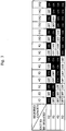
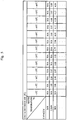
- Fig. 5 is a table showing a calculation example of a COP of a unit in the present embodiment.
Landscapes
- Engineering & Computer Science (AREA)
- Physics & Mathematics (AREA)
- Mechanical Engineering (AREA)
- Thermal Sciences (AREA)
- General Engineering & Computer Science (AREA)
- Chemical & Material Sciences (AREA)
- Combustion & Propulsion (AREA)
- Heat-Pump Type And Storage Water Heaters (AREA)
Claims (11)
- Fluiderwärmungssteuerungssystem, umfassend:einen Fluidkreislauf (10a), der ausgelegt ist, um ein Fluid zwischen einer Vielzahl von Heizeinrichtungen (14a, 14b, 14c), die ausgelegt sind, um das Fluid zu erwärmen, zu zirkulieren, wobei die Vielzahl von Heizeinrichtungen eine Eigenschaft aufweisen, dass die Heizleistung entsprechend der Durchflussmenge des Fluids variiert und ein COP (Leistungskoeffizient) entsprechend der Heizleistung variiert, und einer Anlage, die zumindest beides, einen Tank (11), der ausgelegt ist, um das Fluid zu speichern, und eine Vorrichtung, die ausgelegt ist, um das Fluid als Wärmequelle einzusetzen, enthält;eine Vielzahl von Regelventilen (13a, 13b, 13c), die ausgelegt sind, um die Durchflussmenge des Fluids für jede der Vielzahl von Heizeinrichtungen zu regulieren; undeine Steuervorrichtung (19), die ausgelegt ist, um die Heizleistung von jeder der Vielzahl von Heizeinrichtungen zu bestimmen in einer Weise, dass die Gesamtheizleistung der Vielzahl von Heizeinrichtungen die für die Anlage erforderliche Heizleistung erreicht, und ferner in einer Weise, dass ein gesamter COP der Vielzahl von Heizeinrichtungen einer vorherbestimmten Bedingung genügt, und um jedes der Vielzahl von Regelventilen in einer Weise zu steuern, dass die Heizleistung von jeder der Vielzahl von Heizeinrichtungen die bestimmte Heizleistung erreicht;gekennzeichnet durcheinen Leistungsmesser (23), der ausgelegt ist, um einen Leistungsverbrauch jeder der Vielzahl von Heizeinrichtungen zu messen; und einen Außenlufttemperatursensor (24), der ausgelegt ist, um eine Außenlufttemperatur zu messen,wobei die Steuervorrichtung auf Grundlage der bestimmten Heizleistung, des durch den Leistungsmesser gemessenen Leistungsverbrauchs und der durch den Außenlufttemperatursensor gemessenen Außenlufttemperatur ein Verhältnis zwischen dem COP und der Heizleistung von jeder der Vielzahl von Heizeinrichtungen entsprechend der Außenlufttemperatur erhält, und die Heizleistung von jeder der Vielzahl von Heizeinrichtungen durch Bezug auf das erhaltene Verhältnis bestimmt.
- Fluiderwärmungssteuerungssystem nach Anspruch 1,
wobei die Steuervorrichtung die Heizleistung von jeder der Vielzahl von Heizeinrichtungen bestimmt in einer Weise, dass die Gesamtheizleistung der Vielzahl von Heizeinrichtungen die für die Anlage erforderliche Heizleistung erreicht, und ferner in einer Weise, dass der gesamte COP der Vielzahl von Heizeinrichtungen ein Maximum erreicht. - Fluiderwärmungssystem (10), umfassend:das Fluiderwärmungssteuerungssystem nach einem der Ansprüche 1 und 2; undeine Vielzahl von Heizvorrichtungen, die mit dem Fluiderwärmungssteuerungssystem zu verbinden sind.
- Fluiderwärmungssystem nach Anspruch 3,
wobei die Vielzahl von Heizvorrichtungen zwei oder mehr Heizvorrichtungen mit unterschiedlichen Eigenschaften enthält. - Fluiderwärmungssystem nach einem der Ansprüche 3 und.4,
wobei die Vielzahl von Heizeinrichtungen zwei oder mehr Heizeinrichtungen mit unterschiedlichen Mindestheizleistungen enthält. - Fluiderwärmungssystem nach einem der Ansprüche 3 bis 5, wobei die Vielzahl von Heizeinrichtungen zwei oder mehr Wärmepumpeneinheiten enthält, die unterschiedliche Arten von Kältemitteln verwenden.
- Fluiderwärmungssystem nach einem der Ansprüche 3 bis 6,
wobei die Vielzahl von Heizeinrichtungen eine Wärmepumpeneinheit und eine Heizeinrichtung außer der Wärmepumpeneinheit enthält. - Fluiderwärmungssteuerungssystem nach einem der Ansprüche 1 und 2,
wobei die Steuervorrichtung die Heizleistung, durch welche der COP von jeder der Vielzahl von Heizeinrichtungen ein Maximum erreicht, als optimale Leistung vorab bestimmt, eine Gruppe von Heizeinrichtungen, die aus zumindest einer Heizeinrichtung aus der Vielzahl von Heizeinrichtungen gebildet ist, auswählt, wobei die optimale Gesamtleistung der zumindest einen Heizeinrichtung der für die Anlage erforderlichen Heizleistung entspricht, und jede der Vielzahl von Regelventilen in einer Weise steuert, dass die Gesamtheizleistung der zumindest einen Heizeinrichtung, die die ausgewählte Gruppe von Heizeinrichtungen bildet, die für die Anlage erforderliche Heizleistung erreicht. - Fluiderwärmungssteuerungssystem nach einem der Ansprüche 1 und 2,
wobei die Steuervorrichtung die Heizleistung, durch welche der COP von jeder der Vielzahl von Heizeinrichtungen ein Maximum erreicht, als optimale Leistung vorab bestimmt, und Heizeinrichtungen aus der Vielzahl von Heizeinrichtungen sequentiell auswählt aus einer Heizeinrichtung, deren optimale Leistung gleich oder weniger ist als die für die Anlage erforderliche Heizleistung und deren optimale Leistung außerdem am nächsten zur für die Anlage erforderlichen Heizleistung liegt, und jedes der Vielzahl von Regelventilen in einer Weise steuert, dass die Gesamtheizleistung der ausgewählten Heizeinrichtungen die für die Anlage erforderliche Heizleistung erreicht. - Fluiderwärmungsverfahren, umfassend:einen Schritt des Zirkulierens von Fluid zwischen einer Vielzahl von das Fluid erwärmenden Heizeinrichtungen (14a, 14b, 14c), wobei die Vielzahl von Heizeinrichtungen eine Eigenschaft aufweisen, dass die Heizleistung entsprechend der Durchflussmenge des Fluids variiert und ein COP (Leistungskoeffizient) entsprechend der Heizleistung variiert, und einer Anlage, die zumindest beides, einen Tank (11), der das Fluid speichert, und eine Vorrichtung, die das Fluid als Wärmequelle verwendet, enthält;einen Schritt des Bestimmens der Heizleistung von jeder der Vielzahl von Heizeinrichtungen in einer Weise, dass die Gesamtheizleistung der Vielzahl von Heizeinrichtungen die für die Anlage erforderliche Heizleistung erreicht, und ferner in einer Weise, dass ein Gesamt-COP der Vielzahl von Heizeinrichtungen einer vorherbestimmten Bedingung genügt; undeinen Schritt des Steuerns jedes einer Vielzahl von Regelventilen (13a, 13b, 13c), die die Durchflussmenge des Fluids für jede der Vielzahl von Heizeinrichtungen in einer Weise regulieren, in einer Weise, dass die Heizleistung von jeder der Vielzahl von Heizeinrichtungen die vorbestimmte Heizleistung erreicht;gekennzeichnet durcheinen Leistungsmessungsschritt zum Messen eines Leistungsverbrauchs von jeder der Vielzahl von Heizeinrichtungen; undeinen Außenlufttemperaturerfassungsschritt zum Messen einer Au-ßenlufttemperatur;wobei das Fluiderwärmungsverfahren auf Grundlage der vorbestimmten Heizleistung, des im Leistungsmessungsschritt gemessenen Leistungsverbrauchs und der im Außenlufttemperaturerfassungsschritt gemessenen Außenlufttemperatur ein Verhältnis zwischen dem COP und der Heizleistung von jeder der Vielzahl von Heizeinrichtungen entsprechend der Außenlufttemperatur erhält, und die Heizleistung von jeder der Vielzahl von Heizeinrichtungen durch Bezug auf das erhaltene Verhältnis bestimmt.
- Steuervorrichtung (19), die mit einer Vielzahl von Regelventilen (13a, 13b, 13c) verbunden ist, die in einem Fluidkreislauf (10a) angebracht sind, welcher Fluid zwischen einer Vielzahl von das Fluid erwärmenden Heizeinrichtungen (14a, 14b, 14c) zirkuliert, wobei die Vielzahl von Heizeinrichtungen eine Eigenschaft aufweisen, dass die Heizleistung entsprechend der Durchflussmenge des Fluids variiert und ein COP (Leistugnskoeffizient) entsprechend der Heizleistung variiert, und einer Anlage, umfassend zumindest beides, einen Tank (11), der das Fluid speichert, und eine Vorrichtung, die das Fluid als Wärmequelle verwendet, wobei die Steuervorrichtung umfasst:einen Bestimmungsteil (19b), der ausgelegt ist, um die Heizleistung von jeder der Vielzahl von Heizeinrichtungen in einer Weise zu bestimmen, dass die Gesamtheizleistung der Vielzahl von Heizeinrichtungen die für die Anlage erforderliche Heizleistung erreicht, und ferner in einer Weise, dass ein Gesamt-COP der Vielzahl von Heizeinrichtungen einer vorherbestimmten Bedingung genügt; undeinen Steuerungsteil (19c), der ausgelegt ist, um jedes der Vielzahl von Regelventilen in einer Weise zu steuern, dass die Heizleistung von jeder der Vielzahl von Heizeinrichtungen die bestimmte Heizleistung erreicht;gekennzeichnet durcheinen Detektionsteil (19a), der ausgelegt ist, Daten eines gemessenen Leistungsverbrauchs jeder der Vielzahl von Heizeinrichtungen und eine gemessene Außenlufttemperatur zu erhalten,wobei die Steuervorrichtung auf Grundlage der bestimmten Heizleistung, des gemessenen Leistungsverbrauchs und der gemessenen Außenlufttemperatur ein Verhältnis zwischen dem COP und der Heizleistung von jeder der Vielzahl von Heizeinrichtungen entsprechend der Außenlufttemperatur erhält, und die Heizleistung von jeder der Vielzahl von Heizeinrichtungen durch Bezug auf das erhaltene Verhältnis bestimmt.
Applications Claiming Priority (1)
| Application Number | Priority Date | Filing Date | Title |
|---|---|---|---|
| PCT/JP2009/056514 WO2010116454A1 (ja) | 2009-03-30 | 2009-03-30 | 流体加熱システム及び流体加熱方法及び流体加熱制御システム及び制御装置及び制御方法 |
Publications (3)
| Publication Number | Publication Date |
|---|---|
| EP2416083A1 EP2416083A1 (de) | 2012-02-08 |
| EP2416083A4 EP2416083A4 (de) | 2015-11-04 |
| EP2416083B1 true EP2416083B1 (de) | 2017-05-31 |
Family
ID=42935766
Family Applications (1)
| Application Number | Title | Priority Date | Filing Date |
|---|---|---|---|
| EP09842964.0A Not-in-force EP2416083B1 (de) | 2009-03-30 | 2009-03-30 | System und verfahren zum erwärmen eines fluids und system zur steuerung des erwärmens eines fluids, steuervorrichtung und steuerverfahren |
Country Status (4)
| Country | Link |
|---|---|
| US (1) | US9500376B2 (de) |
| EP (1) | EP2416083B1 (de) |
| JP (1) | JP5132813B2 (de) |
| WO (1) | WO2010116454A1 (de) |
Cited By (1)
| Publication number | Priority date | Publication date | Assignee | Title |
|---|---|---|---|---|
| EP4545868A3 (de) * | 2023-10-03 | 2025-08-13 | A.O. Smith Corporation | Modulare wassererhitzungs- und tanksystemverwaltung |
Families Citing this family (15)
| Publication number | Priority date | Publication date | Assignee | Title |
|---|---|---|---|---|
| JP2014167352A (ja) * | 2011-05-31 | 2014-09-11 | Toshiba Carrier Corp | 加温システム |
| CN102506519B (zh) * | 2011-10-23 | 2013-12-11 | 重庆市电力公司电力科学研究院 | 热电联产机组与风力发电联合供热系统及调度方法 |
| GB2510547B (en) * | 2012-03-01 | 2016-04-27 | Waste Heat Recovery Ltd | Heat recovery |
| JP5447627B1 (ja) * | 2012-09-26 | 2014-03-19 | ダイキン工業株式会社 | 熱源システム制御装置 |
| US9719687B2 (en) * | 2014-01-21 | 2017-08-01 | Intellihot, Inc. | Multi-temperature output fluid heating system |
| WO2015162798A1 (ja) * | 2014-04-25 | 2015-10-29 | 三菱電機株式会社 | ヒートポンプチリングシステム及びその制御方法 |
| JP6109119B2 (ja) * | 2014-07-10 | 2017-04-05 | 三菱電機株式会社 | ヒートポンプ給湯システム |
| CN104676902B (zh) * | 2015-03-11 | 2017-06-30 | 广东美的暖通设备有限公司 | 热泵热水器及其控制方法 |
| KR102815172B1 (ko) | 2020-02-25 | 2025-05-29 | 엘지전자 주식회사 | 히트펌프 및 그 동작방법 |
| US20220003447A1 (en) * | 2020-07-01 | 2022-01-06 | Haier Us Appliance Solutions, Inc. | Air conditioning system with improved coordination between a plurality of units |
| JP7611738B2 (ja) * | 2021-03-10 | 2025-01-10 | 大阪瓦斯株式会社 | 給湯制御装置 |
| WO2024084000A1 (de) * | 2022-10-20 | 2024-04-25 | Peter Brecklinghaus | Nachrüstsatz für ein bereits vorhandenes zentralheizungssystem und ein verfahren zum nachrüsten eines bereits vorhandenen zentralheizungssystems mittels eines nachrüstsatzes |
| EP4560203A1 (de) | 2023-11-24 | 2025-05-28 | BDR Thermea Group B.V. | Wärmepumpensystem |
| US20250271164A1 (en) * | 2024-02-27 | 2025-08-28 | Trane International Inc. | Heat pump and auxiliary heating with carbon reduction reset strategy |
| CN119826220B (zh) * | 2024-12-24 | 2025-11-04 | 珠海格力电器股份有限公司 | 热泵热水系统及其控制方法、电子设备及存储介质 |
Family Cites Families (25)
| Publication number | Priority date | Publication date | Assignee | Title |
|---|---|---|---|---|
| DE2906557C2 (de) * | 1979-02-17 | 1984-07-12 | Joh. Vaillant Gmbh U. Co, 5630 Remscheid | Verfahren und Vorrichtung zum Regeln einer Heizungsanlage mit zwei Wärmequellen |
| JPS60243450A (ja) | 1984-05-17 | 1985-12-03 | 三菱電機株式会社 | 給湯・冷暖房ヒ−トポンプ装置 |
| CH667717A5 (de) * | 1985-04-23 | 1988-10-31 | Landis & Gyr Ag | Verfahren zur leistungsmaessig gesteuerten inbetriebnahme bzw. abschaltung von heizkesseln. |
| EP0445310A1 (de) * | 1990-02-09 | 1991-09-11 | Viessmann Werke GmbH & Co. | Verfahren und Vorrichtung zur Regelung der Vorlauftemperatur in Mehrkessel-Heizungssystemen. |
| EP0900988A1 (de) * | 1997-09-06 | 1999-03-10 | Electrowatt Technology Innovation AG | Verfahren zur Regelung einer Heizungsanlage mit mehreren Wärmeerzeugern |
| JP3758627B2 (ja) * | 2001-11-13 | 2006-03-22 | ダイキン工業株式会社 | ヒートポンプ式給湯装置 |
| JP2003166750A (ja) | 2001-11-30 | 2003-06-13 | Denso Corp | ヒートポンプ式給湯装置 |
| JP3932913B2 (ja) * | 2002-01-29 | 2007-06-20 | ダイキン工業株式会社 | ヒートポンプ式給湯機 |
| JP3742356B2 (ja) * | 2002-03-20 | 2006-02-01 | 株式会社日立製作所 | ヒートポンプ給湯機 |
| JP4305052B2 (ja) | 2003-05-19 | 2009-07-29 | パナソニック株式会社 | ヒートポンプ給湯空調装置 |
| JP4077766B2 (ja) | 2003-06-03 | 2008-04-23 | 松下電器産業株式会社 | ヒートポンプ給湯装置 |
| JP2005090815A (ja) | 2003-09-16 | 2005-04-07 | Matsushita Electric Ind Co Ltd | ヒートポンプ式給湯機 |
| JP4096860B2 (ja) | 2003-10-31 | 2008-06-04 | ダイキン工業株式会社 | ヒートポンプ式給湯装置用の分岐ユニット |
| JP4114613B2 (ja) | 2004-01-27 | 2008-07-09 | 松下電工株式会社 | ヒートポンプ式給湯システム |
| JP4058696B2 (ja) | 2004-05-28 | 2008-03-12 | 日立アプライアンス株式会社 | ヒートポンプ給湯システム |
| JP2006138493A (ja) * | 2004-11-10 | 2006-06-01 | Hanshin Electric Co Ltd | 貯湯式給湯装置 |
| JP2006283989A (ja) * | 2005-03-31 | 2006-10-19 | Sanyo Electric Co Ltd | 冷暖房システム |
| JP2006292281A (ja) | 2005-04-11 | 2006-10-26 | Denso Corp | ヒートポンプ式給湯装置 |
| JP4545691B2 (ja) * | 2006-01-17 | 2010-09-15 | リンナイ株式会社 | 貯湯システム |
| US8733429B2 (en) | 2006-02-13 | 2014-05-27 | The H.L. Turner Group, Inc. | Hybrid heating and/or cooling system |
| JP4753791B2 (ja) * | 2006-05-12 | 2011-08-24 | シャープ株式会社 | ヒートポンプ式給湯機 |
| JP2007322084A (ja) | 2006-06-02 | 2007-12-13 | Hitachi Appliances Inc | ヒートポンプ給湯機 |
| AT503582B1 (de) * | 2006-09-04 | 2007-11-15 | Vaillant Austria Gmbh | Verfahren zum betreiben mehrerer durchlauferhitzer |
| DE202007002733U1 (de) * | 2007-02-24 | 2007-06-06 | Gross, Hermann | Anlage zur Erzeugung, Speicherung und Verteilung von Wärmeenergie zwischen wärmetechnischen Betriebsmitteln mit abgestuften Temperaturniveaus in einem Gebäude und Steigerung zum Betrieb einer solchen Anlage |
| EP2098791A1 (de) * | 2008-03-05 | 2009-09-09 | Roth Werke GmbH | Vorrichtung zur Erwärmung von Wasser |
-
2009
- 2009-03-30 EP EP09842964.0A patent/EP2416083B1/de not_active Not-in-force
- 2009-03-30 JP JP2011508097A patent/JP5132813B2/ja not_active Expired - Fee Related
- 2009-03-30 WO PCT/JP2009/056514 patent/WO2010116454A1/ja not_active Ceased
- 2009-03-30 US US13/255,689 patent/US9500376B2/en not_active Expired - Fee Related
Cited By (1)
| Publication number | Priority date | Publication date | Assignee | Title |
|---|---|---|---|---|
| EP4545868A3 (de) * | 2023-10-03 | 2025-08-13 | A.O. Smith Corporation | Modulare wassererhitzungs- und tanksystemverwaltung |
Also Published As
| Publication number | Publication date |
|---|---|
| JP5132813B2 (ja) | 2013-01-30 |
| EP2416083A4 (de) | 2015-11-04 |
| US9500376B2 (en) | 2016-11-22 |
| WO2010116454A1 (ja) | 2010-10-14 |
| US20110315093A1 (en) | 2011-12-29 |
| JPWO2010116454A1 (ja) | 2012-10-11 |
| EP2416083A1 (de) | 2012-02-08 |
Similar Documents
| Publication | Publication Date | Title |
|---|---|---|
| EP2416083B1 (de) | System und verfahren zum erwärmen eines fluids und system zur steuerung des erwärmens eines fluids, steuervorrichtung und steuerverfahren | |
| US10295199B2 (en) | Water heater controller or system | |
| US7658335B2 (en) | Hydronic heating system | |
| US8538597B2 (en) | System and method for regulating temperature in a hot water heater | |
| JP5597767B2 (ja) | 暖房装置および暖房装置の制御方法 | |
| CN103946761B (zh) | 用于运行和/或监测hvac设备的方法 | |
| EP2356387B1 (de) | Hybridheizsystem | |
| EP2508806B1 (de) | Steuerungsverfahren für Wärmepumpensystem und Wärmepumpeneinheit | |
| EP3136013B1 (de) | Wärmepumpenkühlsystem und steuerungsverfahren dafür | |
| JP5825338B2 (ja) | 給湯制御システム | |
| KR20160047788A (ko) | 온수공급시스템 | |
| US20150369547A1 (en) | Energy measurement system for fluid systems | |
| EP3346197B1 (de) | Heizungssteuerungssystem und warmwasserheizsystem mit wärmepumpe | |
| KR101456878B1 (ko) | 히트펌프 성능평가 시스템의 제어방법 | |
| JP3550336B2 (ja) | 冷暖房システム | |
| JP2009097770A (ja) | ヒートポンプ式温水暖房装置の循環流量算出方法 | |
| EP3382490B1 (de) | Verfahren zur steuerung eines hydronischen heizsystems in mehreren räumen | |
| JP5907158B2 (ja) | 給湯制御システム | |
| JP2002147775A (ja) | 温水暖房システムにおける試運転制御方法 | |
| JP6212990B2 (ja) | 電気機器制御システム | |
| Larson et al. | Laboratory assessment of EcoRuno CO2 air-to-water heat pump | |
| EP4307074A1 (de) | Temperatureinstellungsvorrichtung | |
| JP2024135510A (ja) | ヒートポンプ式給湯システム | |
| JPH0776631B2 (ja) | 吸収式冷温水機の運転制御方法 | |
| GB2528313A (en) | Fluid flow control apparatus for heating or cooling |
Legal Events
| Date | Code | Title | Description |
|---|---|---|---|
| PUAI | Public reference made under article 153(3) epc to a published international application that has entered the european phase |
Free format text: ORIGINAL CODE: 0009012 |
|
| 17P | Request for examination filed |
Effective date: 20110927 |
|
| AK | Designated contracting states |
Kind code of ref document: A1 Designated state(s): AT BE BG CH CY CZ DE DK EE ES FI FR GB GR HR HU IE IS IT LI LT LU LV MC MK MT NL NO PL PT RO SE SI SK TR |
|
| DAX | Request for extension of the european patent (deleted) | ||
| RA4 | Supplementary search report drawn up and despatched (corrected) |
Effective date: 20151001 |
|
| RIC1 | Information provided on ipc code assigned before grant |
Ipc: F24D 19/10 20060101ALI20150925BHEP Ipc: F24D 17/02 20060101ALI20150925BHEP Ipc: F24D 11/02 20060101ALI20150925BHEP Ipc: F24H 1/00 20060101AFI20150925BHEP |
|
| 17Q | First examination report despatched |
Effective date: 20160628 |
|
| REG | Reference to a national code |
Ref country code: DE Ref legal event code: R079 Ref document number: 602009046422 Country of ref document: DE Free format text: PREVIOUS MAIN CLASS: F24H0001000000 Ipc: F25B0030020000 |
|
| GRAP | Despatch of communication of intention to grant a patent |
Free format text: ORIGINAL CODE: EPIDOSNIGR1 |
|
| RIC1 | Information provided on ipc code assigned before grant |
Ipc: F24D 19/10 20060101ALI20161130BHEP Ipc: F24D 11/02 20060101ALI20161130BHEP Ipc: F24D 17/02 20060101ALI20161130BHEP Ipc: F25B 30/02 20060101AFI20161130BHEP |
|
| INTG | Intention to grant announced |
Effective date: 20161222 |
|
| GRAS | Grant fee paid |
Free format text: ORIGINAL CODE: EPIDOSNIGR3 |
|
| GRAA | (expected) grant |
Free format text: ORIGINAL CODE: 0009210 |
|
| AK | Designated contracting states |
Kind code of ref document: B1 Designated state(s): AT BE BG CH CY CZ DE DK EE ES FI FR GB GR HR HU IE IS IT LI LT LU LV MC MK MT NL NO PL PT RO SE SI SK TR |
|
| REG | Reference to a national code |
Ref country code: CH Ref legal event code: EP Ref country code: GB Ref legal event code: FG4D |
|
| REG | Reference to a national code |
Ref country code: AT Ref legal event code: REF Ref document number: 897865 Country of ref document: AT Kind code of ref document: T Effective date: 20170615 |
|
| REG | Reference to a national code |
Ref country code: IE Ref legal event code: FG4D |
|
| REG | Reference to a national code |
Ref country code: SE Ref legal event code: TRGR |
|
| REG | Reference to a national code |
Ref country code: DE Ref legal event code: R096 Ref document number: 602009046422 Country of ref document: DE |
|
| REG | Reference to a national code |
Ref country code: NL Ref legal event code: MP Effective date: 20170531 |
|
| REG | Reference to a national code |
Ref country code: LT Ref legal event code: MG4D |
|
| REG | Reference to a national code |
Ref country code: AT Ref legal event code: MK05 Ref document number: 897865 Country of ref document: AT Kind code of ref document: T Effective date: 20170531 |
|
| PG25 | Lapsed in a contracting state [announced via postgrant information from national office to epo] |
Ref country code: LT Free format text: LAPSE BECAUSE OF FAILURE TO SUBMIT A TRANSLATION OF THE DESCRIPTION OR TO PAY THE FEE WITHIN THE PRESCRIBED TIME-LIMIT Effective date: 20170531 Ref country code: AT Free format text: LAPSE BECAUSE OF FAILURE TO SUBMIT A TRANSLATION OF THE DESCRIPTION OR TO PAY THE FEE WITHIN THE PRESCRIBED TIME-LIMIT Effective date: 20170531 Ref country code: HR Free format text: LAPSE BECAUSE OF FAILURE TO SUBMIT A TRANSLATION OF THE DESCRIPTION OR TO PAY THE FEE WITHIN THE PRESCRIBED TIME-LIMIT Effective date: 20170531 Ref country code: FI Free format text: LAPSE BECAUSE OF FAILURE TO SUBMIT A TRANSLATION OF THE DESCRIPTION OR TO PAY THE FEE WITHIN THE PRESCRIBED TIME-LIMIT Effective date: 20170531 Ref country code: NO Free format text: LAPSE BECAUSE OF FAILURE TO SUBMIT A TRANSLATION OF THE DESCRIPTION OR TO PAY THE FEE WITHIN THE PRESCRIBED TIME-LIMIT Effective date: 20170831 Ref country code: GR Free format text: LAPSE BECAUSE OF FAILURE TO SUBMIT A TRANSLATION OF THE DESCRIPTION OR TO PAY THE FEE WITHIN THE PRESCRIBED TIME-LIMIT Effective date: 20170901 Ref country code: ES Free format text: LAPSE BECAUSE OF FAILURE TO SUBMIT A TRANSLATION OF THE DESCRIPTION OR TO PAY THE FEE WITHIN THE PRESCRIBED TIME-LIMIT Effective date: 20170531 |
|
| PG25 | Lapsed in a contracting state [announced via postgrant information from national office to epo] |
Ref country code: LV Free format text: LAPSE BECAUSE OF FAILURE TO SUBMIT A TRANSLATION OF THE DESCRIPTION OR TO PAY THE FEE WITHIN THE PRESCRIBED TIME-LIMIT Effective date: 20170531 Ref country code: BG Free format text: LAPSE BECAUSE OF FAILURE TO SUBMIT A TRANSLATION OF THE DESCRIPTION OR TO PAY THE FEE WITHIN THE PRESCRIBED TIME-LIMIT Effective date: 20170831 Ref country code: IS Free format text: LAPSE BECAUSE OF FAILURE TO SUBMIT A TRANSLATION OF THE DESCRIPTION OR TO PAY THE FEE WITHIN THE PRESCRIBED TIME-LIMIT Effective date: 20170930 Ref country code: NL Free format text: LAPSE BECAUSE OF FAILURE TO SUBMIT A TRANSLATION OF THE DESCRIPTION OR TO PAY THE FEE WITHIN THE PRESCRIBED TIME-LIMIT Effective date: 20170531 |
|
| PG25 | Lapsed in a contracting state [announced via postgrant information from national office to epo] |
Ref country code: EE Free format text: LAPSE BECAUSE OF FAILURE TO SUBMIT A TRANSLATION OF THE DESCRIPTION OR TO PAY THE FEE WITHIN THE PRESCRIBED TIME-LIMIT Effective date: 20170531 Ref country code: RO Free format text: LAPSE BECAUSE OF FAILURE TO SUBMIT A TRANSLATION OF THE DESCRIPTION OR TO PAY THE FEE WITHIN THE PRESCRIBED TIME-LIMIT Effective date: 20170531 Ref country code: DK Free format text: LAPSE BECAUSE OF FAILURE TO SUBMIT A TRANSLATION OF THE DESCRIPTION OR TO PAY THE FEE WITHIN THE PRESCRIBED TIME-LIMIT Effective date: 20170531 Ref country code: SK Free format text: LAPSE BECAUSE OF FAILURE TO SUBMIT A TRANSLATION OF THE DESCRIPTION OR TO PAY THE FEE WITHIN THE PRESCRIBED TIME-LIMIT Effective date: 20170531 Ref country code: CZ Free format text: LAPSE BECAUSE OF FAILURE TO SUBMIT A TRANSLATION OF THE DESCRIPTION OR TO PAY THE FEE WITHIN THE PRESCRIBED TIME-LIMIT Effective date: 20170531 |
|
| REG | Reference to a national code |
Ref country code: FR Ref legal event code: PLFP Year of fee payment: 10 |
|
| PG25 | Lapsed in a contracting state [announced via postgrant information from national office to epo] |
Ref country code: PL Free format text: LAPSE BECAUSE OF FAILURE TO SUBMIT A TRANSLATION OF THE DESCRIPTION OR TO PAY THE FEE WITHIN THE PRESCRIBED TIME-LIMIT Effective date: 20170531 Ref country code: IT Free format text: LAPSE BECAUSE OF FAILURE TO SUBMIT A TRANSLATION OF THE DESCRIPTION OR TO PAY THE FEE WITHIN THE PRESCRIBED TIME-LIMIT Effective date: 20170531 |
|
| REG | Reference to a national code |
Ref country code: DE Ref legal event code: R097 Ref document number: 602009046422 Country of ref document: DE |
|
| PLBE | No opposition filed within time limit |
Free format text: ORIGINAL CODE: 0009261 |
|
| STAA | Information on the status of an ep patent application or granted ep patent |
Free format text: STATUS: NO OPPOSITION FILED WITHIN TIME LIMIT |
|
| 26N | No opposition filed |
Effective date: 20180301 |
|
| PG25 | Lapsed in a contracting state [announced via postgrant information from national office to epo] |
Ref country code: SI Free format text: LAPSE BECAUSE OF FAILURE TO SUBMIT A TRANSLATION OF THE DESCRIPTION OR TO PAY THE FEE WITHIN THE PRESCRIBED TIME-LIMIT Effective date: 20170531 |
|
| REG | Reference to a national code |
Ref country code: CH Ref legal event code: PL |
|
| PG25 | Lapsed in a contracting state [announced via postgrant information from national office to epo] |
Ref country code: MC Free format text: LAPSE BECAUSE OF FAILURE TO SUBMIT A TRANSLATION OF THE DESCRIPTION OR TO PAY THE FEE WITHIN THE PRESCRIBED TIME-LIMIT Effective date: 20170531 |
|
| REG | Reference to a national code |
Ref country code: BE Ref legal event code: MM Effective date: 20180331 |
|
| REG | Reference to a national code |
Ref country code: IE Ref legal event code: MM4A |
|
| PG25 | Lapsed in a contracting state [announced via postgrant information from national office to epo] |
Ref country code: LU Free format text: LAPSE BECAUSE OF NON-PAYMENT OF DUE FEES Effective date: 20180330 |
|
| PG25 | Lapsed in a contracting state [announced via postgrant information from national office to epo] |
Ref country code: IE Free format text: LAPSE BECAUSE OF NON-PAYMENT OF DUE FEES Effective date: 20180330 |
|
| REG | Reference to a national code |
Ref country code: DE Ref legal event code: R084 Ref document number: 602009046422 Country of ref document: DE |
|
| REG | Reference to a national code |
Ref country code: GB Ref legal event code: 746 Effective date: 20190125 |
|
| PG25 | Lapsed in a contracting state [announced via postgrant information from national office to epo] |
Ref country code: BE Free format text: LAPSE BECAUSE OF NON-PAYMENT OF DUE FEES Effective date: 20180331 Ref country code: CH Free format text: LAPSE BECAUSE OF NON-PAYMENT OF DUE FEES Effective date: 20180331 Ref country code: LI Free format text: LAPSE BECAUSE OF NON-PAYMENT OF DUE FEES Effective date: 20180331 |
|
| PG25 | Lapsed in a contracting state [announced via postgrant information from national office to epo] |
Ref country code: MT Free format text: LAPSE BECAUSE OF NON-PAYMENT OF DUE FEES Effective date: 20180330 |
|
| PG25 | Lapsed in a contracting state [announced via postgrant information from national office to epo] |
Ref country code: TR Free format text: LAPSE BECAUSE OF FAILURE TO SUBMIT A TRANSLATION OF THE DESCRIPTION OR TO PAY THE FEE WITHIN THE PRESCRIBED TIME-LIMIT Effective date: 20170531 |
|
| PGFP | Annual fee paid to national office [announced via postgrant information from national office to epo] |
Ref country code: DE Payment date: 20200317 Year of fee payment: 12 Ref country code: SE Payment date: 20200310 Year of fee payment: 12 Ref country code: GB Payment date: 20200318 Year of fee payment: 12 |
|
| PG25 | Lapsed in a contracting state [announced via postgrant information from national office to epo] |
Ref country code: PT Free format text: LAPSE BECAUSE OF FAILURE TO SUBMIT A TRANSLATION OF THE DESCRIPTION OR TO PAY THE FEE WITHIN THE PRESCRIBED TIME-LIMIT Effective date: 20170531 Ref country code: HU Free format text: LAPSE BECAUSE OF FAILURE TO SUBMIT A TRANSLATION OF THE DESCRIPTION OR TO PAY THE FEE WITHIN THE PRESCRIBED TIME-LIMIT; INVALID AB INITIO Effective date: 20090330 |
|
| PG25 | Lapsed in a contracting state [announced via postgrant information from national office to epo] |
Ref country code: MK Free format text: LAPSE BECAUSE OF NON-PAYMENT OF DUE FEES Effective date: 20170531 Ref country code: CY Free format text: LAPSE BECAUSE OF FAILURE TO SUBMIT A TRANSLATION OF THE DESCRIPTION OR TO PAY THE FEE WITHIN THE PRESCRIBED TIME-LIMIT Effective date: 20170531 |
|
| PGFP | Annual fee paid to national office [announced via postgrant information from national office to epo] |
Ref country code: FR Payment date: 20200214 Year of fee payment: 12 |
|
| REG | Reference to a national code |
Ref country code: DE Ref legal event code: R119 Ref document number: 602009046422 Country of ref document: DE |
|
| GBPC | Gb: european patent ceased through non-payment of renewal fee |
Effective date: 20210330 |
|
| PG25 | Lapsed in a contracting state [announced via postgrant information from national office to epo] |
Ref country code: FR Free format text: LAPSE BECAUSE OF NON-PAYMENT OF DUE FEES Effective date: 20210331 Ref country code: DE Free format text: LAPSE BECAUSE OF NON-PAYMENT OF DUE FEES Effective date: 20211001 Ref country code: SE Free format text: LAPSE BECAUSE OF NON-PAYMENT OF DUE FEES Effective date: 20210331 Ref country code: GB Free format text: LAPSE BECAUSE OF NON-PAYMENT OF DUE FEES Effective date: 20210330 |