EP2418315A2 - Appareil ménager doté d'un capteur de niveau de remplissage et procédé de détermination d'un paramètre d'état dans un appareil ménager - Google Patents
Appareil ménager doté d'un capteur de niveau de remplissage et procédé de détermination d'un paramètre d'état dans un appareil ménager Download PDFInfo
- Publication number
- EP2418315A2 EP2418315A2 EP11174490A EP11174490A EP2418315A2 EP 2418315 A2 EP2418315 A2 EP 2418315A2 EP 11174490 A EP11174490 A EP 11174490A EP 11174490 A EP11174490 A EP 11174490A EP 2418315 A2 EP2418315 A2 EP 2418315A2
- Authority
- EP
- European Patent Office
- Prior art keywords
- light
- light guide
- domestic appliance
- appliance
- optical
- Prior art date
- Legal status (The legal status is an assumption and is not a legal conclusion. Google has not performed a legal analysis and makes no representation as to the accuracy of the status listed.)
- Granted
Links
- 238000000034 method Methods 0.000 title claims abstract description 10
- 230000003287 optical effect Effects 0.000 claims abstract description 95
- 239000007788 liquid Substances 0.000 claims abstract description 76
- 238000005259 measurement Methods 0.000 claims description 45
- 239000013307 optical fiber Substances 0.000 claims description 32
- 238000011156 evaluation Methods 0.000 claims description 24
- 238000004140 cleaning Methods 0.000 claims description 12
- 239000012530 fluid Substances 0.000 claims description 11
- 238000011109 contamination Methods 0.000 claims description 7
- 230000008878 coupling Effects 0.000 claims description 7
- 238000010168 coupling process Methods 0.000 claims description 7
- 238000005859 coupling reaction Methods 0.000 claims description 7
- 239000013505 freshwater Substances 0.000 claims description 4
- XLYOFNOQVPJJNP-UHFFFAOYSA-N water Substances O XLYOFNOQVPJJNP-UHFFFAOYSA-N 0.000 description 26
- 239000006260 foam Substances 0.000 description 15
- 238000005406 washing Methods 0.000 description 15
- 238000010586 diagram Methods 0.000 description 8
- 239000004033 plastic Substances 0.000 description 7
- 229920003023 plastic Polymers 0.000 description 7
- OAICVXFJPJFONN-UHFFFAOYSA-N Phosphorus Chemical compound [P] OAICVXFJPJFONN-UHFFFAOYSA-N 0.000 description 6
- 238000013461 design Methods 0.000 description 6
- 238000010521 absorption reaction Methods 0.000 description 4
- 239000000654 additive Substances 0.000 description 4
- 230000002308 calcification Effects 0.000 description 4
- 238000001514 detection method Methods 0.000 description 4
- 238000000605 extraction Methods 0.000 description 4
- 230000000737 periodic effect Effects 0.000 description 4
- 230000001419 dependent effect Effects 0.000 description 3
- 239000003599 detergent Substances 0.000 description 3
- 230000010354 integration Effects 0.000 description 3
- 230000005540 biological transmission Effects 0.000 description 2
- 238000011161 development Methods 0.000 description 2
- 239000000835 fiber Substances 0.000 description 2
- 238000001914 filtration Methods 0.000 description 2
- 239000007850 fluorescent dye Substances 0.000 description 2
- 239000011888 foil Substances 0.000 description 2
- 239000011521 glass Substances 0.000 description 2
- 239000012535 impurity Substances 0.000 description 2
- 238000002347 injection Methods 0.000 description 2
- 239000007924 injection Substances 0.000 description 2
- 229920003229 poly(methyl methacrylate) Polymers 0.000 description 2
- 239000004926 polymethyl methacrylate Substances 0.000 description 2
- 238000012545 processing Methods 0.000 description 2
- 230000002123 temporal effect Effects 0.000 description 2
- 238000012935 Averaging Methods 0.000 description 1
- 230000002411 adverse Effects 0.000 description 1
- 239000003570 air Substances 0.000 description 1
- 230000015572 biosynthetic process Effects 0.000 description 1
- 238000011088 calibration curve Methods 0.000 description 1
- 239000003990 capacitor Substances 0.000 description 1
- 229910052729 chemical element Inorganic materials 0.000 description 1
- 239000003086 colorant Substances 0.000 description 1
- 239000004020 conductor Substances 0.000 description 1
- 238000010276 construction Methods 0.000 description 1
- 238000012937 correction Methods 0.000 description 1
- 230000008021 deposition Effects 0.000 description 1
- 230000023077 detection of light stimulus Effects 0.000 description 1
- 239000003989 dielectric material Substances 0.000 description 1
- 230000005684 electric field Effects 0.000 description 1
- 230000008030 elimination Effects 0.000 description 1
- 238000003379 elimination reaction Methods 0.000 description 1
- 230000007613 environmental effect Effects 0.000 description 1
- 239000000284 extract Substances 0.000 description 1
- 238000005187 foaming Methods 0.000 description 1
- 238000009499 grossing Methods 0.000 description 1
- 238000001746 injection moulding Methods 0.000 description 1
- 230000031700 light absorption Effects 0.000 description 1
- 238000012423 maintenance Methods 0.000 description 1
- 239000000463 material Substances 0.000 description 1
- 239000002245 particle Substances 0.000 description 1
- 229910052698 phosphorus Inorganic materials 0.000 description 1
- 239000011574 phosphorus Substances 0.000 description 1
- 229920000642 polymer Polymers 0.000 description 1
- 238000002360 preparation method Methods 0.000 description 1
- 239000008237 rinsing water Substances 0.000 description 1
- 239000000523 sample Substances 0.000 description 1
- 239000004065 semiconductor Substances 0.000 description 1
- 230000035945 sensitivity Effects 0.000 description 1
- 238000000926 separation method Methods 0.000 description 1
- 239000002689 soil Substances 0.000 description 1
- 239000000758 substrate Substances 0.000 description 1
- 238000009736 wetting Methods 0.000 description 1
Images



Classifications
-
- D—TEXTILES; PAPER
- D06—TREATMENT OF TEXTILES OR THE LIKE; LAUNDERING; FLEXIBLE MATERIALS NOT OTHERWISE PROVIDED FOR
- D06F—LAUNDERING, DRYING, IRONING, PRESSING OR FOLDING TEXTILE ARTICLES
- D06F39/00—Details of washing machines not specific to a single type of machines covered by groups D06F9/00 - D06F27/00
- D06F39/08—Liquid supply or discharge arrangements
- D06F39/087—Water level measuring or regulating devices
-
- A—HUMAN NECESSITIES
- A47—FURNITURE; DOMESTIC ARTICLES OR APPLIANCES; COFFEE MILLS; SPICE MILLS; SUCTION CLEANERS IN GENERAL
- A47L—DOMESTIC WASHING OR CLEANING; SUCTION CLEANERS IN GENERAL
- A47L15/00—Washing or rinsing machines for crockery or tableware
- A47L15/42—Details
- A47L15/4244—Water-level measuring or regulating arrangements
-
- D—TEXTILES; PAPER
- D06—TREATMENT OF TEXTILES OR THE LIKE; LAUNDERING; FLEXIBLE MATERIALS NOT OTHERWISE PROVIDED FOR
- D06F—LAUNDERING, DRYING, IRONING, PRESSING OR FOLDING TEXTILE ARTICLES
- D06F2103/00—Parameters monitored or detected for the control of domestic laundry washing machines, washer-dryers or laundry dryers
- D06F2103/18—Washing liquid level
Definitions
- the invention relates to a domestic appliance with at least one level sensor.
- the domestic appliance can in particular be a water-conducting domestic appliance, in particular a laundry cleaning appliance.
- the invention further relates to a method for determining at least one state parameter in a domestic appliance.
- the state parameter may in particular be a liquid-related state parameter, in particular a fill level.
- EP 1 610 102 A1 discloses a device for detecting the level in a container.
- a container preferably for storing condensate in a household tumble dryer, to be monitored with regard to its filling state.
- the container has a cavity enclosing walls of dielectric material, preferably plastic, and formed of electrically conductive material electrodes as elements of an electrical capacitor, which is coupled in the operating position of the container with an evaluation circuit.
- To improve the measuring sensitivity and accuracy of the cavity-forming body of the container has a formation having two opposing boundary walls, which correspond closely to the at least approximately parallel to each other electrodes and whose distance from each other is suitable for usually small measuring voltages between the Electrodes to create an approximately interference-free electric field.
- WO 2009/027242 A1 relates to an apparatus and method for determining a level within a tub of a washing machine.
- the device for determining a level of liquid within a container of a water-conducting household appliance, in particular a washing machine is equipped with a level sensor, by means of which a pressure value generated by the liquid is to be detected, wherein the level sensor at least with a detection part in a during the Washing process is arranged with the liquid covered lower portion of the container.
- a determination device can be provided, by means of which the fill level of the liquid can be determined on the basis of the pressure value detected by the fill level sensor.
- a domestic appliance comprising at least one fill level sensor, wherein the at least one fill level sensor comprises at least one optical fill level sensor.
- An optical fill level sensor may, in particular, be understood to mean a sensor or measuring probe whose (disembodied) measuring medium or measuring carrier is light.
- the optical level sensor is thus based on at least one optical measurement for determining in particular a level in the domestic appliance.
- the use of light as the measuring carrier has the advantage that a very high measuring resolution is allowed. Also, a measurement inertia when using light is very low, so that even dynamic state parameters can be detected with an acceptable outlay. Furthermore, the optical level sensor requires only a few, and moreover, no moving, parts, so that a robust and inexpensive construction is made possible.
- the at least one optical level sensor can be assigned to an evaluation unit, for example a microprocessor.
- the evaluation unit is set up in particular for determining at least one state parameter of the liquid in the household appliance on the basis of the measurement data received by the at least one light sensor.
- the evaluation unit may be, for example, a dedicated evaluation unit or else a central control unit.
- the at least one state parameter may include, for example, a level, a refractive index, a haze, a concentration of additives, a level of soil, a movement (e.g., a slosh), and / or a viscosity of the liquid.
- the evaluation unit can also be set up to determine at least one state parameter of the domestic appliance, e.g. for determining a degree of calcification, an imbalance of the loaded household appliance, etc.
- the optical level sensor at least one at least partially wettable with a liquid light guide, at least one light source by means of the light in the light guide can be coupled and at least one light sensor for detecting coupled out of the light guide light.
- a light guide extending at least over the maximum level or level to be measured can be fed by means of the at least one light source with light of suitable wavelength. At least a portion of the injected or injected light can be totally reflected on the walls of the at least one light guide.
- the degree of total reflection differs between dry wall areas and wet or wetted with the liquid, especially water, wall areas.
- the angle of the total reflection in the light guide can in particular be such that the majority of the light is reflected back into the interior of the light guide on the dry wall areas of the light guide and, in the case of wet wall areas, a defined larger portion of the light exits into the surrounding liquid.
- Detection of light locally extracted from the light guide by means of the at least one light sensor thus provides a change, in particular attenuation, of the outcoupled light as a function of the fill level. For example, the higher the liquid is, the more light can escape at the wet wall portions or sides of the light pipe, and the weaker is the light incident into the at least one light sensor.
- the at least one light source comprises at least one light-emitting diode. If several LEDs are present, they can be lit in the same color or in different colors. A color may be monochrome (e.g., red, green, blue, etc.) or multichrome (e.g., white).
- the light emitted by the at least one light-emitting diode can also be an infrared light (IR LED) or an ultraviolet light (UV LED).
- the at least one light-emitting diode can be in the form of at least one individually housed light-emitting diode or in the form of at least one LED chip. Several LED chips can be mounted on a common substrate ("submount").
- the at least one light emitting diode may be equipped with at least one own and / or common optics for beam guidance, e.g. at least one Fresnel lens, a collimator, and so on.
- at least one own and / or common optics for beam guidance e.g. at least one Fresnel lens, a collimator, and so on.
- organic light-emitting diodes OLEDs, for example polymer OLEDs
- the LEDs have the advantage of being very durable, robust, narrowband, compact and easy to control.
- the at least one light source may be e.g. have at least one diode laser.
- the at least one light source is not limited to a semiconductor light source and may be e.g. also include other lasers, incandescent lamps, fluorescent tubes, etc.
- the liquid may be, for example, water or a washing liquid (e.g., liquid wash liquor).
- the liquid may contain additives of various kinds, such as cleaning additives or impurities.
- cleaning additives water can also be referred to as a liquor.
- the water can thus also be generally considered to be a water-based liquid.
- the domestic appliance has at least one evaluation unit for determining at least one state parameter, in particular a fill level, of the liquid in the household appliance on the basis of the measurement data received by the at least one light sensor.
- the light guide is essentially made of a translucent for the light emitted from the light source of light plastic, for example of PMMA.
- the optical waveguide can have an inhomogeneous refractive index, in particular an index of refraction varying from the inside to the outside, in order to minimize optical losses at reflection points. For a simple and inexpensive design of the Fiber optic this may have a homogeneous refractive index.
- the light guide can then be produced in particular as an injection molded part.
- the light source and the light sensor may be provided as separate components or as an integrated unit (optical transceiver), preferably on a common carrier. If the light source and the light sensor are designed as a transceiver, the light can be detected by the light sensor in particular after reflection at a free end of the light guide. The free end can then be mirrored in particular for an increase in the luminous efficacy.
- At least one wall or surface in particular a surface region provided as a light passage region, may have at least one optical function, e.g. be designed as a converging lens, a diverging lens, a prism, a mirror, etc.
- the domestic appliance may in particular be a laundry care appliance, e.g. a washing machine or a washer-dryer, but also, for example, a tumble dryer, a dishwasher, etc. If the domestic appliance is a laundry cleaning appliance such as a washing machine or a washer-dryer, the liquid may in particular be water (lye, rinse water, etc.).
- the optical fiber can be inserted during a mounting of the tub between two tub halves.
- the optical waveguide is arranged at least in sections on an inner side of a lye container.
- the light guide is then advantageously at least approximately similar to the shape of the inside of the tub, eg cylinder sector similar. Since the liquor rises in the tub, results in a simple level measurement by the wetting of accommodated in the tub optical fiber range. A possible nonlinearity between the light intensity detected by the at least one light sensor and the fill level due to a curvature of the light guide can be taken into account by using corresponding characteristic curves.
- the light guide is a foil.
- the optical fiber can be produced particularly inexpensively, made compact and used in confined spaces.
- several optical fibers can also be integrated into the film, e.g. for parallel measurements.
- the optical fiber may be a film applied to the inside of the tub.
- a gap between the tub and a laundry drum need not be redesigned, and there is a particularly simple integration of the optical level sensor in the laundry cleaning device.
- the light guide is integrated in a container wall of a liquid container.
- the container wall can be configured as such as the light guide, e.g. by a preparation of a translucent for the light, in particular transparent, plastic or glass.
- the optical fiber is integrated in the tub.
- the tub may in particular be made at least partially of a plastic suitable as a light guide.
- the tub may e.g. be at least partially made of a permeable to the light of the light source plastic, over the allowed level range.
- the domestic appliance has an integrated optical measuring unit with at least one optical level sensor and a measuring tube, wherein at least one side wall of the measuring tube forms part of a light guide of the at least one optical level sensor.
- the measuring tube is connected by means of at least one fluid channel with a liquid container of the domestic appliance, whose level is measured by means of the optical measuring unit. Due to the principle of the communicating tubes, the level of the liquid container can be imaged and determined in the measuring tube. As a result, the optical level measurement can also be arranged at a distance from the liquid container, which allows a high degree of design flexibility.
- the measuring tube can be configured, for example, as a cuvette.
- the at least one light source and the at least one light sensor may have been preassembled on the light guide prior to assembly of the optical measuring unit in the domestic appliance.
- the at least one light source and the at least one light sensor can in particular be designed as at least one optical transceiver.
- the at least one light source couples light of several wavelengths into the at least one light guide
- the at least one light sensor detects light of these several wavelengths
- the evaluation unit is set up on the basis of the measurement data received by the at least one light sensor several wavelengths to determine a state parameter of the liquid surrounding the optical fiber ('spectroscopic measurement').
- the light of the several or different wavelengths can be coupled sequentially or simultaneously into the at least one light guide.
- the spectroscopic measurement can provide additional information about the refractive index of the liquid surrounding the optical waveguide. In this case, use is made of the fact that the proportion decoupled from the optical waveguide is dependent on the refractive index of the medium to be measured under otherwise identical circumstances (in particular with the same fill level).
- the absorption at a wavelength as a function of the fill level is given by a function (describable, for example, by a family of characteristics whose parameter is the refractive index of the surrounding medium).
- a function for different wavelengths sufficiently large differences in the characteristic curves are assumed, so that for measured absorption values for the different wavelengths at identical levels and an identical refractive index for the given situation, the respective curve of the characteristic field is clearly defined.
- additional information about a lye concentration or a dirt content of the liquid can be obtained therefrom.
- An integration of any number of other light sources and light sensors is relatively easy.
- a determination of the refractive index of the liquid surrounding the optical fiber is also possible by means of a measurement with only one wavelength, if a defined level is known.
- the defined level can be achieved for example by a targeted filling with the liquid. It is exploited that given Level, the amount of light transmitted in the light guide depends inter alia on the refractive index of the surrounding medium.
- a calibration curve of the sensor then has an additional dimension, namely the refractive index of the surrounding medium or, in the case of a discrete plot, a characteristic field. Assuming a constant dependence on the refractive index, the curves in the characteristic field are free from overlapping, it is initially not clear in a measurement on which characteristic curve in the characteristic field the measuring point is located.
- the characteristic is already identifiable by a single known point, this point can be determined by a known parameter, in this case a defined filling level.
- the defined filling level can be set with a second sensor, here for example the flow sensor. So that no disturbances of the measurement take place through the laundry in the case of a drum filled with laundry, the measuring point is preferably below a submerged area of the drum.
- the optical level sensor has two spaced-apart, optically coupled optical fiber, wherein one of the optical fibers is optically coupled to the at least one light source and at least the other of the optical fibers, in particular both optical fibers, is optically coupled to at least one light sensor ,
- one of the optical fibers is optically coupled to the at least one light source and at least the other of the optical fibers, in particular both optical fibers, is optically coupled to at least one light sensor .
- the second light guide can be treated with at least one phosphor (fluorescence dye, also called phosphor, but not to be confused with the chemical element phosphorus) be. Incorporated light is reduced in frequency by the phosphor (so-called 'downconversion'), whereby the total reflection angle changes along with a reduced probability of leakage or loss.
- phosphor fluorescence dye, also called phosphor, but not to be confused with the chemical element phosphorus
- the evaluation unit can be set up to differentiate different media, in particular media of different consistency. This can be done, for example, that the optical level sensor two spaced apart, with each other optically coupled optical fiber, wherein one of the optical fibers is optically coupled to the at least one light source and both optical fibers are optically coupled to at least one respective light sensor, in this case, for example, water for a good light transmission from a first of the optical fibers to provide a second of the optical fibers For example, while foam also decouples light from the first light pipe, but to a lesser degree than the water.
- the foam is not transparent (transparent), but translucent (opaque)
- light coupled out of the first optical waveguide into the foam is coupled into the second optical waveguide only to a small extent and is mainly spread away laterally.
- the coupled into due to the foam in the second light guide light fraction is therefore negligible against the injected due to the water content of light.
- water and foam are separated from each other by sensors.
- a quantity of foam can be determined and the level of the liquid can be determined more accurately.
- the knowledge of the amount of foam can be used for example to determine a time at which detergent is washed out of a laundry (low foaming).
- optical measurement can be further optical properties of the media (liquid, foam, etc.) in the household appliance capture, such as the turbidity.
- the turbidity can be determined, for example, by absorption of light by a predetermined absorption path filled with the liquid.
- the absorption path may, for example, correspond to a level measuring section in the optical level sensor.
- the turbidity sensor principle can thus be integrated into the optical level sensor.
- the at least one light guide has a stepped or discontinuous structure.
- the step-by-step design makes it possible to measure even in the case of heavy soiling and adverse environmental conditions by detecting and counting corresponding steps in the measuring signal, for example with defined measuring points respectively at the steps and interpolation between them.
- the stepped structure may in particular comprise a stepped structure of an outside or surface of the light guide.
- the outside or surface of the optical waveguide can be designed, for example, in the form of at least one periodic function, in particular along a longitudinal alignment of the optical waveguide.
- the periodic function may, for example be a sine function, a triangle function or a rectangular function.
- the periodic function is characterized by the course of the light signal due to its different degree of light extraction. Although a contamination of the surface of the light guide can attenuate the measurable light intensity or the like as a whole, the width of the steps changed by the pollution but only slightly and is still easy to detect.
- the domestic appliance has at least two optical level sensors of different types and at least one evaluation unit for the common evaluation of the measurement data received from the at least two optical level sensors. As a result, further information about a state of the liquid and / or the domestic appliance can be obtained.
- the evaluation unit is set up to determine a vibration state of the liquid and / or the domestic appliance on the basis of the measurement data. It is exploited that the optical measurement enables a very fast acquisition of measured values. There is practically no smoothing of the measuring signals due to the measuring principle. Thus, at a given level, it is possible to vibrate vibrating and fluidly (fluid) mechanically coupled parts of the domestic appliance with respect to phase and amplitude of vibration (especially periodic sloshing (strong movement of the water surface due to vibration system dynamics)) of the fluid derive.
- This information (s) may e.g. for intelligent laundry distribution (i.e., reversing the drum controlled by special algorithms for redistribution of laundry).
- a pairwise use of optical level sensors at different points in a tub permits detection of diagonal imbalances which are not or only with difficulty detectable with conventional 3D sensors alone.
- two or more sensors can detect a movement of a surface of the liquid better, which in turn allows conclusions about a Diagonalunwucht.
- the evaluation unit is set up to determine at least one fluid mechanical property of the fluid, in particular a viscosity, on the basis of the measurement data.
- the optical level sensor is particular fast enough to detect oscillating or sloshing levels or water levels.
- An averaging to determine the (average) level can be done for example by filtering the measurement signal;
- analog filters in particular, digital filters, software filters or the like come into question.
- a mechanical low-pass system can be used, for example, by the above-described spatial separation of the liquid container and the optical level sensor and their hydraulic connection according to the principle of communicating tubes, in which the level in the measuring tube practically does not follow a vibration of the liquid in the liquid container.
- a logical filtering e.g. By means of electronics and / or software, it is also possible to extract information on (fluid) mechanical data from the measurement signal, for example a viscosity of the fluid, e.g. Suds.
- the viscosity in turn, can be used as an input to determine the purity of the liquid. It can be exploited here that, according to the Hagen-Poiseuille law, a flow velocity in a tube (under laminar conditions) is inversely proportional to the viscosity of the liquid. From a measurement of a flow rate or a decay of a vibration in a pipe system or similar data can therefore be inferred to the viscosity.
- the evaluation unit is adapted to determine on the basis of the measurement data at least one contamination parameter of the water-bearing household appliance and to initiate on the basis thereof at least one step provided for the elimination of contamination of the water-bearing household appliance.
- reference or compensation signals of the optical level sensor can be used to detect contamination of the machine.
- a calcification of the light guide can be detected by an increased light extraction at the reflection points in comparison to a non-calcified light guide, in particular by means of a reference measurement in an unfilled state, for example, before a run-in of water at the beginning of a wash cycle or a wash cycle.
- This can for example a single reference measurement provides information about a degree of occupancy of the fiber optic cable but not about its distribution.
- By comparison with the known for the new unpolluted light guide light extraction can be concluded that the average contamination of the light guide. From the already mentioned above spectroscopic measurements or measurements at defined water levels, additional information about a vertical distribution of pollution can be obtained.
- the steps for eliminating the pollution may be e.g. performing a self-cleaning program and / or issuing an indication, e.g. a maintenance notice or the like, to a user.
- an indication e.g. a maintenance notice or the like
- the optical level sensor can be in addition to statements about the degree of pollution and information on their homogeneity and distribution (eg with a calcification with a clear focus in a lower area) and gain their temporal evolution and control of the household appliance use.
- the at least one optical level sensor in particular its at least one optical fiber, is arranged in an inflow region of fresh water of the household appliance.
- the inflowing fresh water, the optical level sensor can be flushed free of impurities, for example, to allow a precise detection of foam. It may be possible to interrupt the fresh water supply (for a short time) for a particularly precise measurement.
- the flushable sensor may be used as a reference (such as to detect a machine condition) along with a second optical level sensor at a non-flushable location.
- level measurement is not limited to a water based liquid but may be e.g. also be used for liquid detergents and so on. Accordingly, the invention is not limited to water-bearing domestic appliances.
- the task can be further developed in particular analogous to the household appliance described above.
- the invention has the advantages that, with a simultaneously high integration density, there is a cost advantage and a smaller number of components compared to conventional sensors.
- Parallel measurement across different optical principles e.g., outcoupling vs. coupling, different wavelengths, etc.
- a zero measurement may also provide information about a degree of soiling of the measuring device and thus e.g. with a washing machine over the tub.
- Including temporal aspects provides more information about the system (e.g., a viscosity of the fluid).
- optical level meter can be used for level measurement, it can also measure other condition parameters and does not even need to be used for level measurement.
- the optical level meter can therefore also be referred to as an optical fluid meter.
- Fig.1 shows a sectional view in side view of a schematic diagram of an optical level sensor 1 according to a first embodiment.
- the optical level sensor 1 has an at least partially wettable with liquid F rod-shaped optical fiber 2 PMMA of length L, which is perpendicular here in a fillable by the liquid F liquid container, eg in a tub of a washing machine.
- a longitudinal section of the light guide 2 surrounded or wetted by the fluid F corresponds to a filling level h.
- the light beam S which can be coupled into the light guide 2 is here generated by a light-emitting diode 4 and is essentially monochrome.
- the light beam S passes through the light guide 2 and, since it runs obliquely to the longitudinal axis of the light guide 2, several times on the side wall or lateral surface 5 of the light guide 2 is totally reflected until it exits or decouples at the other, second end face 6 and a light sensor. 7 falls.
- the second end surface 6 is also not wetted by the liquid F.
- the total reflection is when the lateral surface 5 at locations dry or not wetted with the liquid F, is substantially lossless or low lossy and then, when the lateral surface 5 wet at the place of total reflection or wetted with the liquid F, substantially stronger lossy. At the lossy Total reflection is given a certain proportion of the incident on the lateral surface 5 from the inside light S as scattered light T to the outside.
- an evaluation unit 8 functionally coupled to the light sensor 7, e.g. a control unit of a domestic appliance 9, from the measured data of the light sensor 7 determine the filling level h.
- the evaluation unit 8 can be used e.g. Use one or more characteristics or look-up tables, which correlate the measurement data of the light sensor 7 with the level h.
- the light emitting diode 4 and / or the light sensor 7 may be mounted substantially directly on the light guide 2 or spaced therefrom.
- the light-emitting diode 4 and the light sensor 7 may be arranged on a same end surface 3 or 6, in particular on a same support, wherein the light sensor 7 then detects light which has been reflected back at the other end surface 6 or 3 and thus the light guide 2 twice has gone through. This arrangement is particularly compact and has an increased accuracy of measurement. To reduce light losses at the end face 3 or 6 reflecting the light back, this end face 3 or 6 may be mirrored.
- the light-emitting diode 4 and the light sensor 7 can in particular form a common optical transceiver unit, see also Fig.2 ,
- the transceiver unit may also have electronics, for example for controlling the light-emitting diode 4 and / or for processing or processing the signals of the light sensor 7.
- the domestic appliance 9 may in particular be a water-conducting household appliance such as a laundry cleaning appliance (washing machine, washer-dryer, etc.).
- the liquid F can then be in particular a water-based liquid, in particular a lye or rinsing water.
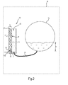
- Fig.2 shows a sectional view in side view of a schematic diagram of an optical level sensor 11 according to a second embodiment.
- the filling level sensor 11 is an integral part of an optical measuring unit 12, which additionally has a measuring tube 13 and a liquid channel 14.
- the measuring tube 13 is by means of the liquid channel 14 according to the principle of communicating tubes with a liquid container 15th a household appliance 16 hydraulically connected. This corresponds to a level or level in the measuring tube 13 a level or level in the liquid container 15.
- the liquid container 15 is here a tub of a laundry cleaning device.
- the light guide 17 of the optical level sensor 11 simultaneously represents a side wall 18 of the measuring tube 13, and both functional elements 17, 13 can be manufactured in one piece, in particular by means of a plastic injection method.
- the measuring tube 13 is designed here as a cuvette with plane-parallel side walls.
- the optical measuring unit 12 has a recess 12a for receiving an optical transceiver 19.
- the optical transceiver 19 is directed directly adjacent to a light (on and off) coupling surface 20 of the light guide.
- the light coupling surface 20 may be configured to form the light beam for high light output as an optical element, e.g. lenticular.
- An opposite end surface 21 of the light guide 17 serves as a reflection surface and can be used for high light output e.g. be mirrored.
- the optical transceiver 19 can be pre-assembled in the recess 12a prior to mounting the optical measuring unit in the domestic appliance.
- Figure 3 shows a sectional side view of a schematic diagram of an optical level sensor 21 according to a third embodiment for use in a domestic appliance 24.
- the optical level sensor 21 now has two spaced-apart, optically coupled together optical fibers 22, 23.
- the two light guides 22, 23 have the same shape and the same base material and are aligned parallel and adjacent to each other.
- the first optical fiber 22 is optically coupled to the light emitting diode 4 through the first end surface 3a, and is coupled to a first light sensor 7a through the opposite end surface 6a.
- the second optical waveguide 23 has a light sensor 7b on its second end face 6b, but no light-emitting diode.
- the first end face 6b is mirrored so that light incident thereto from the inside is reflected back and can travel toward the second end face 6b.
- the second light guide 23 is offset with at least one phosphor (fluorescent dye, 'phosphor'). Incorporated light is through the fluorescent in frequency reduces (so-called 'downconversion'), whereby the total reflection angle changes along with a reduced probability of leakage or loss.
- the light emerging during a reflection in the first optical waveguide 22 (which previously corresponds to the scattered light not used further) is then coupled laterally into the second optical waveguide 23 by the liquid F.
- the light intensity measured at the second optical fiber 23 or the like. thus increases with increasing level or level h of liquid F.
- the optical level sensor 21 can be used here, for example, to detect air A, liquid F and foam B quantitatively.
- the liquid F standing between the light guides 22, 23 results in a good transmission of light to the second optical waveguide 23.
- the lather B increasingly extracts light from the first light waveguide 22 (although not to the same extent as through the liquid F), but then scattered by the foam B and coupled only negligibly into the second light guide 23.
- a scattering loss can be estimated by the foam B.
- the influence of the foam B can then in turn be used to correct a level determination which is e.g. is performed by means of the first light guide 22, are used.
- the knowledge of the amount of foam or foam height may also be used as an input to control an operating cycle of the domestic appliance 24, for example for determining a time when detergent is washed out of a laundry.
- Figure 4 shows a sectional view in side view of a schematic diagram of an optical level sensor 31 according to a fourth embodiment.
- the optical waveguide 32 of the optical fill level sensor 31 is now provided, at least on one side region (in this case, the lateral surface 34), with a structure 33 which is stepped in a longitudinal extent, in particular a rectangular one.
- This structure can be achieved in a light guide 32, for example by a regular introduction of circumferential grooves in the lateral surface 34 of the light guide 32.
- FIG. 5 shows a matching plot of a detected by the optical level sensor 31 light intensity I as a function of a level h, each in any units.
- Figure 6 shows a side view of a tub 41 a washing machine 42 with three possible light guides 43, 44, 45th
- the optical waveguide 43 has a part 43a which conformally curves to an inner side 46 of the tub 41 and which is continued downwards through the sump 47 of the tub 41.
- an optical transceiver 19 is arranged at an lower free end of the light guide 43 outside of the tub 41.
- a level h e.g. a lye
- a nonlinear relationship between the filling level h and the light received at the transceiver 19 or the light attenuation due to the non-linear design in the filling direction can be taken into account in the evaluation unit 8, e.g. by using appropriate corrections, e.g. Characteristics.
- the light guide 43 may be configured as a foil at least with respect to its curved part 43a.
- the use of the film allows a particularly cost-effective, space-saving and easy-to-install design.
- a light guide 44 may be used, which is constructed similar to the light guide 43, but is attached to an outer side 48 of the tub 41 surface contacting.
- at least the area of the tub 41 located in front of the light guide 44 is translucent, in particular substantially transparent, for the wavelength (s) used in the optical measurement.
- a wavelength (s) used for the optical measurement may be more translucent integral portion of the tub 41 serve as a light guide of the optical level meter.
- the light guides 43 and 44 have the advantage that they can be positioned between the lateral surfaces of the tub and a rotatably mounted in the tub washing drum.
- the light guide 45 is a rectilinear, upright optical fiber, which may also be positioned within the tub between the tub and the washing drum, outside the tub or in the tub can be integrated. Also, the light guide 45 may be used as a volume element, e.g. be formed as a rod-shaped element, or as a film.
- any other suitable light source can be used instead of the light-emitting diode, for example a laser diode or a wide-angle light source with a downstream filter. It is generally preferred that the incident light be narrow band.
Landscapes
- Engineering & Computer Science (AREA)
- Textile Engineering (AREA)
- Measurement Of Levels Of Liquids Or Fluent Solid Materials (AREA)
- Control Of Washing Machine And Dryer (AREA)
- Investigating Or Analysing Materials By Optical Means (AREA)
Applications Claiming Priority (1)
| Application Number | Priority Date | Filing Date | Title |
|---|---|---|---|
| DE102010038668A DE102010038668A1 (de) | 2010-07-29 | 2010-07-29 | Hausgerät mit Füllstandssensor und Verfahren zum Bestimmen eines Zustandsparameters in einem Hausgerät |
Publications (3)
| Publication Number | Publication Date |
|---|---|
| EP2418315A2 true EP2418315A2 (fr) | 2012-02-15 |
| EP2418315A3 EP2418315A3 (fr) | 2016-07-06 |
| EP2418315B1 EP2418315B1 (fr) | 2019-12-25 |
Family
ID=45406943
Family Applications (1)
| Application Number | Title | Priority Date | Filing Date |
|---|---|---|---|
| EP11174490.0A Active EP2418315B1 (fr) | 2010-07-29 | 2011-07-19 | Appareil ménager doté d'un dispositif de mesure et procédé de détermination d'un paramètre d'état dans un appareil ménager |
Country Status (2)
| Country | Link |
|---|---|
| EP (1) | EP2418315B1 (fr) |
| DE (1) | DE102010038668A1 (fr) |
Cited By (8)
| Publication number | Priority date | Publication date | Assignee | Title |
|---|---|---|---|---|
| DE202013100830U1 (de) | 2013-02-26 | 2014-06-04 | Sick Ag | Optoelektronischer Füllstandssensor |
| DE202013100833U1 (de) | 2013-02-26 | 2014-06-04 | Sick Ag | Optoelektronischer Sensor zur Bestimmung eines Füllstands eines Mediums in einem Behälter |
| EP2770308A1 (fr) | 2013-02-26 | 2014-08-27 | Sick Ag | Capteur de niveau de remplissage optoélectronique |
| EP2770307A1 (fr) | 2013-02-26 | 2014-08-27 | Sick Ag | Capteur optoélectronique et procédé de détermination d'un niveau de remplissage d'un fluide dans un récipient |
| IT201800001818A1 (it) * | 2018-01-25 | 2019-07-25 | Candy Spa | Metodo per valutare automaticamente la presenza di schiuma in una macchina lavastoviglie |
| DE102018107590A1 (de) | 2018-03-29 | 2019-10-02 | Sita Messtechnik Gmbh | Schaumanalysegerät |
| US11202347B2 (en) | 2019-08-26 | 2021-12-14 | Haier Us Appliance Solutions, Inc. | Over-the-range microwaves having one or more airflow features |
| CN114108232A (zh) * | 2021-12-02 | 2022-03-01 | Tcl家用电器(合肥)有限公司 | 泡沫量预测方法、装置、存储介质以及洗涤设备 |
Families Citing this family (6)
| Publication number | Priority date | Publication date | Assignee | Title |
|---|---|---|---|---|
| SI2591713T1 (sl) | 2013-01-29 | 2023-05-31 | V-Zug Ag | Gospodinjski aparat s senzorjem nivoja vode |
| DE102015209013A1 (de) * | 2015-05-18 | 2016-12-08 | Volkswagen Aktiengesellschaft | Verfahren und Vorrichtung zur Generierung von Effektlicht |
| DE102015008200A1 (de) * | 2015-06-26 | 2016-12-29 | Hella Kgaa Hueck & Co. | Sensorvorrichtung zur Bestimmung eines Füllstandes eines Fluids in einem Fahrzeug |
| DE102015224946A1 (de) | 2015-12-11 | 2017-06-14 | BSH Hausgeräte GmbH | Kombiniertes optisches Behälter- und Füllstandserkennungssystem |
| DE102017222088A1 (de) * | 2017-12-06 | 2019-06-06 | BSH Hausgeräte GmbH | Wäschepflegegerät mit einer Steuerung |
| DE102018118178A1 (de) * | 2018-07-27 | 2020-01-30 | Miele & Cie. Kg | Behälter zur Aufnahme und Abgabe eines Duftstoffs in den Behandlungsraum eines Haushaltsgeräts sowie Haushaltsgerät mit einem derartigen Behälter |
Citations (2)
| Publication number | Priority date | Publication date | Assignee | Title |
|---|---|---|---|---|
| EP1610102A1 (fr) | 2004-06-22 | 2005-12-28 | BSH Bosch und Siemens Hausgeräte GmbH | Dispositif pour la détermination du niveau de remplissage dans un réservoir |
| WO2009027242A1 (fr) | 2007-08-24 | 2009-03-05 | BSH Bosch und Siemens Hausgeräte GmbH | Procédé et dispositif pour déterminer le niveau de remplissage d'une cuve d'un lave-linge |
Family Cites Families (7)
| Publication number | Priority date | Publication date | Assignee | Title |
|---|---|---|---|---|
| FR2451023A1 (fr) * | 1979-03-06 | 1980-10-03 | Bosch Siemens Hausgeraete | Indicateur de niveau de liquide optique, en particulier pour appareils menagers |
| DE19821148A1 (de) * | 1998-05-12 | 1999-11-18 | Aeg Hausgeraete Gmbh | Programmgesteuertes wasserführendes elektrisches Haushaltsgerät |
| JP3124759B2 (ja) * | 1998-07-14 | 2001-01-15 | エルジー電子株式会社 | 洗濯機の水位/振動感知方法及び装置 |
| DE19936574A1 (de) * | 1999-08-03 | 2001-02-08 | Schrodt Stephan | Optischer Sensor zur kontinuierlichen Feststellung des Füllstandes eines flüssigen Mediums in einem Behälter |
| DE19945925A1 (de) * | 1999-09-24 | 2001-03-29 | Bsh Bosch Siemens Hausgeraete | Wasserführendes Haushaltgerät |
| DE102004003077A1 (de) * | 2004-01-21 | 2005-08-11 | Electrolux Home Products Corp. N.V. | Vorrichtung und Verfahren zur Niveauüberwachung in einem flüssigkeitsführenden Haushaltsgerät |
| DE102007012166B4 (de) * | 2007-03-12 | 2023-06-29 | Sanhua Aweco Appliance Systems Gmbh | Haushaltsmaschine |
-
2010
- 2010-07-29 DE DE102010038668A patent/DE102010038668A1/de not_active Withdrawn
-
2011
- 2011-07-19 EP EP11174490.0A patent/EP2418315B1/fr active Active
Patent Citations (2)
| Publication number | Priority date | Publication date | Assignee | Title |
|---|---|---|---|---|
| EP1610102A1 (fr) | 2004-06-22 | 2005-12-28 | BSH Bosch und Siemens Hausgeräte GmbH | Dispositif pour la détermination du niveau de remplissage dans un réservoir |
| WO2009027242A1 (fr) | 2007-08-24 | 2009-03-05 | BSH Bosch und Siemens Hausgeräte GmbH | Procédé et dispositif pour déterminer le niveau de remplissage d'une cuve d'un lave-linge |
Cited By (16)
| Publication number | Priority date | Publication date | Assignee | Title |
|---|---|---|---|---|
| DE202013100830U1 (de) | 2013-02-26 | 2014-06-04 | Sick Ag | Optoelektronischer Füllstandssensor |
| DE202013100833U1 (de) | 2013-02-26 | 2014-06-04 | Sick Ag | Optoelektronischer Sensor zur Bestimmung eines Füllstands eines Mediums in einem Behälter |
| EP2770308A1 (fr) | 2013-02-26 | 2014-08-27 | Sick Ag | Capteur de niveau de remplissage optoélectronique |
| EP2770307A1 (fr) | 2013-02-26 | 2014-08-27 | Sick Ag | Capteur optoélectronique et procédé de détermination d'un niveau de remplissage d'un fluide dans un récipient |
| DE102013101889A1 (de) | 2013-02-26 | 2014-08-28 | Sick Ag | Optoelektronischer Füllstandssensor |
| DE102013101890A1 (de) | 2013-02-26 | 2014-08-28 | Sick Ag | Optoelektronischer Sensor und Verfahren zur Bestimmung eines Füllstands eines Mediums in einem Behälter |
| DE102013101890B4 (de) * | 2013-02-26 | 2016-06-02 | Sick Ag | Optoelektronischer Sensor und Verfahren zur Bestimmung eines Füllstands eines Mediums in einem Behälter |
| CN110074737A (zh) * | 2018-01-25 | 2019-08-02 | 坎迪股份公司 | 餐具清洗机、自动评价其泡沫的存在的方法和系统 |
| IT201800001818A1 (it) * | 2018-01-25 | 2019-07-25 | Candy Spa | Metodo per valutare automaticamente la presenza di schiuma in una macchina lavastoviglie |
| EP3524125A1 (fr) * | 2018-01-25 | 2019-08-14 | Candy S.p.A. | Procédé d'évaluation automatique de la présence de mousse dans un lave-vaisselle |
| CN110074737B (zh) * | 2018-01-25 | 2024-03-15 | 坎迪股份公司 | 餐具清洗机、自动评价其泡沫的存在的方法和系统 |
| DE102018107590A1 (de) | 2018-03-29 | 2019-10-02 | Sita Messtechnik Gmbh | Schaumanalysegerät |
| DE102018107590B4 (de) | 2018-03-29 | 2022-08-11 | Sita Messtechnik Gmbh | Schaumanalysegerät |
| US11202347B2 (en) | 2019-08-26 | 2021-12-14 | Haier Us Appliance Solutions, Inc. | Over-the-range microwaves having one or more airflow features |
| CN114108232A (zh) * | 2021-12-02 | 2022-03-01 | Tcl家用电器(合肥)有限公司 | 泡沫量预测方法、装置、存储介质以及洗涤设备 |
| CN114108232B (zh) * | 2021-12-02 | 2024-03-12 | Tcl家用电器(合肥)有限公司 | 泡沫量预测方法、装置、存储介质以及洗涤设备 |
Also Published As
| Publication number | Publication date |
|---|---|
| DE102010038668A1 (de) | 2012-02-02 |
| EP2418315A3 (fr) | 2016-07-06 |
| EP2418315B1 (fr) | 2019-12-25 |
Similar Documents
| Publication | Publication Date | Title |
|---|---|---|
| EP2418315B1 (fr) | Appareil ménager doté d'un dispositif de mesure et procédé de détermination d'un paramètre d'état dans un appareil ménager | |
| DE112010002873B4 (de) | Optischer Sensor zum Erfassen des Flüssigkeitsniveaus in einem Behälter, insbesondere für einen lösbaren Behälter für ein elektrisches Haushaltsgerät, sowie eine zugeordnete Linse und Verfahren | |
| DE102011102627B4 (de) | Waschmaschine oder Geschirrspülmaschine mit einem optischen Sensor | |
| DE19806559B4 (de) | Verfahren und Vorrichtung zur Behandlung von Geschirr in Spülmaschinen | |
| EP3475477B1 (fr) | Procédé de commande améliorée d'un appareil ménager conducteur d'eau et appareil ménager associé | |
| DE4336520C2 (de) | Optischer Sensor und seine Verwendung | |
| DE102007011119A1 (de) | Waschmaschine mit automatischer Regelung des Waschprozesses | |
| DE10201767A1 (de) | Haushaltsmaschine zum Reinigen von Haushaltsgegenständen | |
| DE102016205756A1 (de) | Verfahren zur verbesserten Steuerung eines wasserführenden Haushaltsgerätes und hierzu geeignetes Haushaltsgerät | |
| EP2133455A1 (fr) | Procédé et dispositif de détermination de mousse dans un lave-linge | |
| EP1412574B1 (fr) | Procede pour exploiter un appareil menager porteur d'eau et appareil menager | |
| DE19904280A1 (de) | Vorrichtung zur Ermittlung von Ablagerungen an Glasoberflächen in Spülmaschinen | |
| DE102008056701B4 (de) | Optischer Schaumsensor | |
| EP0992622A2 (fr) | Procédé pour surveiller et commander le procédé de rinçage d'une machine à laver et machine à laver fonctionnant selon ce procédé | |
| EP3589934A1 (fr) | Procédé et dispositif d'examen optique d'un liquide | |
| DE19714695C2 (de) | Wasch- oder Geschirrspülmaschine mit Trübungssensor | |
| DE19806560B4 (de) | Verfahren und Vorrichtung zum Waschen und/oder Spülen von Wäsche in Waschmaschinen bzw. Waschtrocknern | |
| DE10354856A1 (de) | Verfahren und Anordnung zur Bestimmung von Veränderungen der Oberflächenspannung sowie zur Ermittlung des Niveaus transparenter Fluide | |
| EP4484926A1 (fr) | Appareil ménager doté d'un dispositif de détection | |
| DE112023000400T5 (de) | Flüssigkeitsanalysesystem, wasserführendes haushaltsgerät und verfahren zur bestimmung einer konzentration | |
| DE19714664C2 (de) | Wasch- oder Spülmaschine mit Trübungssensor | |
| DE3908548A1 (de) | Verfahren zur messung des fluessigkeitsstandes in einem behaelter und messfuehler zur durchfuehrung des verfahrens | |
| EP2591713B1 (fr) | Appareil ménager avec capteur de niveau d'eau | |
| WO2017097477A1 (fr) | Système optique combiné de détection de récipient et de niveau | |
| EP3538705B1 (fr) | Procédé de commande améliorée d'un appareil électroménager à circulation d'eau et appareil électroménager associé |
Legal Events
| Date | Code | Title | Description |
|---|---|---|---|
| AK | Designated contracting states |
Kind code of ref document: A2 Designated state(s): AL AT BE BG CH CY CZ DE DK EE ES FI FR GB GR HR HU IE IS IT LI LT LU LV MC MK MT NL NO PL PT RO RS SE SI SK SM TR |
|
| AX | Request for extension of the european patent |
Extension state: BA ME |
|
| PUAI | Public reference made under article 153(3) epc to a published international application that has entered the european phase |
Free format text: ORIGINAL CODE: 0009012 |
|
| RAP1 | Party data changed (applicant data changed or rights of an application transferred) |
Owner name: BSH HAUSGERAETE GMBH |
|
| PUAL | Search report despatched |
Free format text: ORIGINAL CODE: 0009013 |
|
| AK | Designated contracting states |
Kind code of ref document: A3 Designated state(s): AL AT BE BG CH CY CZ DE DK EE ES FI FR GB GR HR HU IE IS IT LI LT LU LV MC MK MT NL NO PL PT RO RS SE SI SK SM TR |
|
| AX | Request for extension of the european patent |
Extension state: BA ME |
|
| RIC1 | Information provided on ipc code assigned before grant |
Ipc: D06F 39/08 20060101AFI20160601BHEP Ipc: A47L 15/42 20060101ALI20160601BHEP |
|
| STAA | Information on the status of an ep patent application or granted ep patent |
Free format text: STATUS: REQUEST FOR EXAMINATION WAS MADE |
|
| 17P | Request for examination filed |
Effective date: 20170109 |
|
| RBV | Designated contracting states (corrected) |
Designated state(s): AL AT BE BG CH CY CZ DE DK EE ES FI FR GB GR HR HU IE IS IT LI LT LU LV MC MK MT NL NO PL PT RO RS SE SI SK SM TR |
|
| GRAP | Despatch of communication of intention to grant a patent |
Free format text: ORIGINAL CODE: EPIDOSNIGR1 |
|
| STAA | Information on the status of an ep patent application or granted ep patent |
Free format text: STATUS: GRANT OF PATENT IS INTENDED |
|
| INTG | Intention to grant announced |
Effective date: 20190819 |
|
| GRAS | Grant fee paid |
Free format text: ORIGINAL CODE: EPIDOSNIGR3 |
|
| GRAA | (expected) grant |
Free format text: ORIGINAL CODE: 0009210 |
|
| STAA | Information on the status of an ep patent application or granted ep patent |
Free format text: STATUS: THE PATENT HAS BEEN GRANTED |
|
| AK | Designated contracting states |
Kind code of ref document: B1 Designated state(s): AL AT BE BG CH CY CZ DE DK EE ES FI FR GB GR HR HU IE IS IT LI LT LU LV MC MK MT NL NO PL PT RO RS SE SI SK SM TR |
|
| REG | Reference to a national code |
Ref country code: GB Ref legal event code: FG4D Free format text: NOT ENGLISH |
|
| REG | Reference to a national code |
Ref country code: CH Ref legal event code: EP |
|
| REG | Reference to a national code |
Ref country code: DE Ref legal event code: R096 Ref document number: 502011016346 Country of ref document: DE |
|
| REG | Reference to a national code |
Ref country code: AT Ref legal event code: REF Ref document number: 1217238 Country of ref document: AT Kind code of ref document: T Effective date: 20200115 |
|
| REG | Reference to a national code |
Ref country code: IE Ref legal event code: FG4D Free format text: LANGUAGE OF EP DOCUMENT: GERMAN |
|
| REG | Reference to a national code |
Ref country code: NL Ref legal event code: MP Effective date: 20191225 |
|
| PG25 | Lapsed in a contracting state [announced via postgrant information from national office to epo] |
Ref country code: SE Free format text: LAPSE BECAUSE OF FAILURE TO SUBMIT A TRANSLATION OF THE DESCRIPTION OR TO PAY THE FEE WITHIN THE PRESCRIBED TIME-LIMIT Effective date: 20191225 Ref country code: LV Free format text: LAPSE BECAUSE OF FAILURE TO SUBMIT A TRANSLATION OF THE DESCRIPTION OR TO PAY THE FEE WITHIN THE PRESCRIBED TIME-LIMIT Effective date: 20191225 Ref country code: LT Free format text: LAPSE BECAUSE OF FAILURE TO SUBMIT A TRANSLATION OF THE DESCRIPTION OR TO PAY THE FEE WITHIN THE PRESCRIBED TIME-LIMIT Effective date: 20191225 Ref country code: GR Free format text: LAPSE BECAUSE OF FAILURE TO SUBMIT A TRANSLATION OF THE DESCRIPTION OR TO PAY THE FEE WITHIN THE PRESCRIBED TIME-LIMIT Effective date: 20200326 Ref country code: NO Free format text: LAPSE BECAUSE OF FAILURE TO SUBMIT A TRANSLATION OF THE DESCRIPTION OR TO PAY THE FEE WITHIN THE PRESCRIBED TIME-LIMIT Effective date: 20200325 Ref country code: BG Free format text: LAPSE BECAUSE OF FAILURE TO SUBMIT A TRANSLATION OF THE DESCRIPTION OR TO PAY THE FEE WITHIN THE PRESCRIBED TIME-LIMIT Effective date: 20200325 Ref country code: FI Free format text: LAPSE BECAUSE OF FAILURE TO SUBMIT A TRANSLATION OF THE DESCRIPTION OR TO PAY THE FEE WITHIN THE PRESCRIBED TIME-LIMIT Effective date: 20191225 |
|
| REG | Reference to a national code |
Ref country code: LT Ref legal event code: MG4D |
|
| PG25 | Lapsed in a contracting state [announced via postgrant information from national office to epo] |
Ref country code: RS Free format text: LAPSE BECAUSE OF FAILURE TO SUBMIT A TRANSLATION OF THE DESCRIPTION OR TO PAY THE FEE WITHIN THE PRESCRIBED TIME-LIMIT Effective date: 20191225 Ref country code: HR Free format text: LAPSE BECAUSE OF FAILURE TO SUBMIT A TRANSLATION OF THE DESCRIPTION OR TO PAY THE FEE WITHIN THE PRESCRIBED TIME-LIMIT Effective date: 20191225 |
|
| PG25 | Lapsed in a contracting state [announced via postgrant information from national office to epo] |
Ref country code: AL Free format text: LAPSE BECAUSE OF FAILURE TO SUBMIT A TRANSLATION OF THE DESCRIPTION OR TO PAY THE FEE WITHIN THE PRESCRIBED TIME-LIMIT Effective date: 20191225 |
|
| PG25 | Lapsed in a contracting state [announced via postgrant information from national office to epo] |
Ref country code: RO Free format text: LAPSE BECAUSE OF FAILURE TO SUBMIT A TRANSLATION OF THE DESCRIPTION OR TO PAY THE FEE WITHIN THE PRESCRIBED TIME-LIMIT Effective date: 20191225 Ref country code: CZ Free format text: LAPSE BECAUSE OF FAILURE TO SUBMIT A TRANSLATION OF THE DESCRIPTION OR TO PAY THE FEE WITHIN THE PRESCRIBED TIME-LIMIT Effective date: 20191225 Ref country code: EE Free format text: LAPSE BECAUSE OF FAILURE TO SUBMIT A TRANSLATION OF THE DESCRIPTION OR TO PAY THE FEE WITHIN THE PRESCRIBED TIME-LIMIT Effective date: 20191225 Ref country code: NL Free format text: LAPSE BECAUSE OF FAILURE TO SUBMIT A TRANSLATION OF THE DESCRIPTION OR TO PAY THE FEE WITHIN THE PRESCRIBED TIME-LIMIT Effective date: 20191225 Ref country code: PT Free format text: LAPSE BECAUSE OF FAILURE TO SUBMIT A TRANSLATION OF THE DESCRIPTION OR TO PAY THE FEE WITHIN THE PRESCRIBED TIME-LIMIT Effective date: 20200520 |
|
| PG25 | Lapsed in a contracting state [announced via postgrant information from national office to epo] |
Ref country code: IS Free format text: LAPSE BECAUSE OF FAILURE TO SUBMIT A TRANSLATION OF THE DESCRIPTION OR TO PAY THE FEE WITHIN THE PRESCRIBED TIME-LIMIT Effective date: 20200425 Ref country code: SK Free format text: LAPSE BECAUSE OF FAILURE TO SUBMIT A TRANSLATION OF THE DESCRIPTION OR TO PAY THE FEE WITHIN THE PRESCRIBED TIME-LIMIT Effective date: 20191225 Ref country code: SM Free format text: LAPSE BECAUSE OF FAILURE TO SUBMIT A TRANSLATION OF THE DESCRIPTION OR TO PAY THE FEE WITHIN THE PRESCRIBED TIME-LIMIT Effective date: 20191225 |
|
| REG | Reference to a national code |
Ref country code: DE Ref legal event code: R097 Ref document number: 502011016346 Country of ref document: DE |
|
| PG25 | Lapsed in a contracting state [announced via postgrant information from national office to epo] |
Ref country code: ES Free format text: LAPSE BECAUSE OF FAILURE TO SUBMIT A TRANSLATION OF THE DESCRIPTION OR TO PAY THE FEE WITHIN THE PRESCRIBED TIME-LIMIT Effective date: 20191225 Ref country code: DK Free format text: LAPSE BECAUSE OF FAILURE TO SUBMIT A TRANSLATION OF THE DESCRIPTION OR TO PAY THE FEE WITHIN THE PRESCRIBED TIME-LIMIT Effective date: 20191225 |
|
| PLBE | No opposition filed within time limit |
Free format text: ORIGINAL CODE: 0009261 |
|
| STAA | Information on the status of an ep patent application or granted ep patent |
Free format text: STATUS: NO OPPOSITION FILED WITHIN TIME LIMIT |
|
| PG25 | Lapsed in a contracting state [announced via postgrant information from national office to epo] |
Ref country code: SI Free format text: LAPSE BECAUSE OF FAILURE TO SUBMIT A TRANSLATION OF THE DESCRIPTION OR TO PAY THE FEE WITHIN THE PRESCRIBED TIME-LIMIT Effective date: 20191225 |
|
| 26N | No opposition filed |
Effective date: 20200928 |
|
| PG25 | Lapsed in a contracting state [announced via postgrant information from national office to epo] |
Ref country code: IT Free format text: LAPSE BECAUSE OF FAILURE TO SUBMIT A TRANSLATION OF THE DESCRIPTION OR TO PAY THE FEE WITHIN THE PRESCRIBED TIME-LIMIT Effective date: 20191225 |
|
| PG25 | Lapsed in a contracting state [announced via postgrant information from national office to epo] |
Ref country code: PL Free format text: LAPSE BECAUSE OF FAILURE TO SUBMIT A TRANSLATION OF THE DESCRIPTION OR TO PAY THE FEE WITHIN THE PRESCRIBED TIME-LIMIT Effective date: 20191225 Ref country code: MC Free format text: LAPSE BECAUSE OF FAILURE TO SUBMIT A TRANSLATION OF THE DESCRIPTION OR TO PAY THE FEE WITHIN THE PRESCRIBED TIME-LIMIT Effective date: 20191225 |
|
| REG | Reference to a national code |
Ref country code: CH Ref legal event code: PL |
|
| GBPC | Gb: european patent ceased through non-payment of renewal fee |
Effective date: 20200719 |
|
| REG | Reference to a national code |
Ref country code: BE Ref legal event code: MM Effective date: 20200731 |
|
| PG25 | Lapsed in a contracting state [announced via postgrant information from national office to epo] |
Ref country code: FR Free format text: LAPSE BECAUSE OF NON-PAYMENT OF DUE FEES Effective date: 20200731 Ref country code: GB Free format text: LAPSE BECAUSE OF NON-PAYMENT OF DUE FEES Effective date: 20200719 Ref country code: LU Free format text: LAPSE BECAUSE OF NON-PAYMENT OF DUE FEES Effective date: 20200719 Ref country code: LI Free format text: LAPSE BECAUSE OF NON-PAYMENT OF DUE FEES Effective date: 20200731 Ref country code: CH Free format text: LAPSE BECAUSE OF NON-PAYMENT OF DUE FEES Effective date: 20200731 |
|
| PG25 | Lapsed in a contracting state [announced via postgrant information from national office to epo] |
Ref country code: BE Free format text: LAPSE BECAUSE OF NON-PAYMENT OF DUE FEES Effective date: 20200731 |
|
| PG25 | Lapsed in a contracting state [announced via postgrant information from national office to epo] |
Ref country code: IE Free format text: LAPSE BECAUSE OF NON-PAYMENT OF DUE FEES Effective date: 20200719 |
|
| REG | Reference to a national code |
Ref country code: AT Ref legal event code: MM01 Ref document number: 1217238 Country of ref document: AT Kind code of ref document: T Effective date: 20200719 |
|
| PG25 | Lapsed in a contracting state [announced via postgrant information from national office to epo] |
Ref country code: AT Free format text: LAPSE BECAUSE OF NON-PAYMENT OF DUE FEES Effective date: 20200719 |
|
| PG25 | Lapsed in a contracting state [announced via postgrant information from national office to epo] |
Ref country code: TR Free format text: LAPSE BECAUSE OF FAILURE TO SUBMIT A TRANSLATION OF THE DESCRIPTION OR TO PAY THE FEE WITHIN THE PRESCRIBED TIME-LIMIT Effective date: 20191225 Ref country code: MT Free format text: LAPSE BECAUSE OF FAILURE TO SUBMIT A TRANSLATION OF THE DESCRIPTION OR TO PAY THE FEE WITHIN THE PRESCRIBED TIME-LIMIT Effective date: 20191225 Ref country code: CY Free format text: LAPSE BECAUSE OF FAILURE TO SUBMIT A TRANSLATION OF THE DESCRIPTION OR TO PAY THE FEE WITHIN THE PRESCRIBED TIME-LIMIT Effective date: 20191225 |
|
| PG25 | Lapsed in a contracting state [announced via postgrant information from national office to epo] |
Ref country code: MK Free format text: LAPSE BECAUSE OF FAILURE TO SUBMIT A TRANSLATION OF THE DESCRIPTION OR TO PAY THE FEE WITHIN THE PRESCRIBED TIME-LIMIT Effective date: 20191225 |
|
| PGFP | Annual fee paid to national office [announced via postgrant information from national office to epo] |
Ref country code: DE Payment date: 20220731 Year of fee payment: 12 |
|
| REG | Reference to a national code |
Ref country code: DE Ref legal event code: R084 Ref document number: 502011016346 Country of ref document: DE |
|
| REG | Reference to a national code |
Ref country code: DE Ref legal event code: R119 Ref document number: 502011016346 Country of ref document: DE |
|
| PG25 | Lapsed in a contracting state [announced via postgrant information from national office to epo] |
Ref country code: DE Free format text: LAPSE BECAUSE OF NON-PAYMENT OF DUE FEES Effective date: 20240201 |