EP4484926A1 - Appareil ménager doté d'un dispositif de détection - Google Patents
Appareil ménager doté d'un dispositif de détection Download PDFInfo
- Publication number
- EP4484926A1 EP4484926A1 EP24176714.4A EP24176714A EP4484926A1 EP 4484926 A1 EP4484926 A1 EP 4484926A1 EP 24176714 A EP24176714 A EP 24176714A EP 4484926 A1 EP4484926 A1 EP 4484926A1
- Authority
- EP
- European Patent Office
- Prior art keywords
- light
- household appliance
- color
- sensor device
- liquid
- Prior art date
- Legal status (The legal status is an assumption and is not a legal conclusion. Google has not performed a legal analysis and makes no representation as to the accuracy of the status listed.)
- Withdrawn
Links
Images


Classifications
-
- D—TEXTILES; PAPER
- D06—TREATMENT OF TEXTILES OR THE LIKE; LAUNDERING; FLEXIBLE MATERIALS NOT OTHERWISE PROVIDED FOR
- D06F—LAUNDERING, DRYING, IRONING, PRESSING OR FOLDING TEXTILE ARTICLES
- D06F34/00—Details of control systems for washing machines, washer-dryers or laundry dryers
- D06F34/14—Arrangements for detecting or measuring specific parameters
- D06F34/22—Condition of the washing liquid, e.g. turbidity
-
- G—PHYSICS
- G01—MEASURING; TESTING
- G01N—INVESTIGATING OR ANALYSING MATERIALS BY DETERMINING THEIR CHEMICAL OR PHYSICAL PROPERTIES
- G01N21/00—Investigating or analysing materials by the use of optical means, i.e. using sub-millimetre waves, infrared, visible or ultraviolet light
- G01N21/17—Systems in which incident light is modified in accordance with the properties of the material investigated
- G01N21/25—Colour; Spectral properties, i.e. comparison of effect of material on the light at two or more different wavelengths or wavelength bands
-
- G—PHYSICS
- G01—MEASURING; TESTING
- G01N—INVESTIGATING OR ANALYSING MATERIALS BY DETERMINING THEIR CHEMICAL OR PHYSICAL PROPERTIES
- G01N21/00—Investigating or analysing materials by the use of optical means, i.e. using sub-millimetre waves, infrared, visible or ultraviolet light
- G01N21/17—Systems in which incident light is modified in accordance with the properties of the material investigated
- G01N21/25—Colour; Spectral properties, i.e. comparison of effect of material on the light at two or more different wavelengths or wavelength bands
- G01N21/251—Colorimeters; Construction thereof
-
- A—HUMAN NECESSITIES
- A47—FURNITURE; DOMESTIC ARTICLES OR APPLIANCES; COFFEE MILLS; SPICE MILLS; SUCTION CLEANERS IN GENERAL
- A47L—DOMESTIC WASHING OR CLEANING; SUCTION CLEANERS IN GENERAL
- A47L15/00—Washing or rinsing machines for crockery or tableware
- A47L15/42—Details
- A47L15/4297—Arrangements for detecting or measuring the condition of the washing water, e.g. turbidity
-
- G—PHYSICS
- G01—MEASURING; TESTING
- G01J—MEASUREMENT OF INTENSITY, VELOCITY, SPECTRAL CONTENT, POLARISATION, PHASE OR PULSE CHARACTERISTICS OF INFRARED, VISIBLE OR ULTRAVIOLET LIGHT; COLORIMETRY; RADIATION PYROMETRY
- G01J3/00—Spectrometry; Spectrophotometry; Monochromators; Measuring colours
- G01J3/02—Details
- G01J3/10—Arrangements of light sources specially adapted for spectrometry or colorimetry
-
- G—PHYSICS
- G01—MEASURING; TESTING
- G01J—MEASUREMENT OF INTENSITY, VELOCITY, SPECTRAL CONTENT, POLARISATION, PHASE OR PULSE CHARACTERISTICS OF INFRARED, VISIBLE OR ULTRAVIOLET LIGHT; COLORIMETRY; RADIATION PYROMETRY
- G01J3/00—Spectrometry; Spectrophotometry; Monochromators; Measuring colours
- G01J3/46—Measurement of colour; Colour measuring devices, e.g. colorimeters
-
- G—PHYSICS
- G01—MEASURING; TESTING
- G01N—INVESTIGATING OR ANALYSING MATERIALS BY DETERMINING THEIR CHEMICAL OR PHYSICAL PROPERTIES
- G01N21/00—Investigating or analysing materials by the use of optical means, i.e. using sub-millimetre waves, infrared, visible or ultraviolet light
- G01N21/17—Systems in which incident light is modified in accordance with the properties of the material investigated
- G01N21/25—Colour; Spectral properties, i.e. comparison of effect of material on the light at two or more different wavelengths or wavelength bands
- G01N21/255—Details, e.g. use of specially adapted sources, lighting or optical systems
-
- G—PHYSICS
- G01—MEASURING; TESTING
- G01N—INVESTIGATING OR ANALYSING MATERIALS BY DETERMINING THEIR CHEMICAL OR PHYSICAL PROPERTIES
- G01N21/00—Investigating or analysing materials by the use of optical means, i.e. using sub-millimetre waves, infrared, visible or ultraviolet light
- G01N21/17—Systems in which incident light is modified in accordance with the properties of the material investigated
- G01N21/47—Scattering, i.e. diffuse reflection
- G01N21/49—Scattering, i.e. diffuse reflection within a body or fluid
- G01N21/53—Scattering, i.e. diffuse reflection within a body or fluid within a flowing fluid, e.g. smoke
- G01N21/534—Scattering, i.e. diffuse reflection within a body or fluid within a flowing fluid, e.g. smoke by measuring transmission alone, i.e. determining opacity
-
- G—PHYSICS
- G01—MEASURING; TESTING
- G01N—INVESTIGATING OR ANALYSING MATERIALS BY DETERMINING THEIR CHEMICAL OR PHYSICAL PROPERTIES
- G01N21/00—Investigating or analysing materials by the use of optical means, i.e. using sub-millimetre waves, infrared, visible or ultraviolet light
- G01N21/84—Systems specially adapted for particular applications
- G01N21/85—Investigating moving fluids or granular solids
- G01N21/8507—Probe photometers, i.e. with optical measuring part dipped into fluid sample
-
- H—ELECTRICITY
- H04—ELECTRIC COMMUNICATION TECHNIQUE
- H04B—TRANSMISSION
- H04B10/00—Transmission systems employing electromagnetic waves other than radio-waves, e.g. infrared, visible or ultraviolet light, or employing corpuscular radiation, e.g. quantum communication
- H04B10/40—Transceivers
- H04B10/43—Transceivers using a single component as both light source and receiver, e.g. using a photoemitter as a photoreceiver
-
- D—TEXTILES; PAPER
- D06—TREATMENT OF TEXTILES OR THE LIKE; LAUNDERING; FLEXIBLE MATERIALS NOT OTHERWISE PROVIDED FOR
- D06F—LAUNDERING, DRYING, IRONING, PRESSING OR FOLDING TEXTILE ARTICLES
- D06F2103/00—Parameters monitored or detected for the control of domestic laundry washing machines, washer-dryers or laundry dryers
- D06F2103/20—Washing liquid condition, e.g. turbidity
-
- D—TEXTILES; PAPER
- D06—TREATMENT OF TEXTILES OR THE LIKE; LAUNDERING; FLEXIBLE MATERIALS NOT OTHERWISE PROVIDED FOR
- D06F—LAUNDERING, DRYING, IRONING, PRESSING OR FOLDING TEXTILE ARTICLES
- D06F2103/00—Parameters monitored or detected for the control of domestic laundry washing machines, washer-dryers or laundry dryers
- D06F2103/64—Radiation, e.g. microwaves
- D06F2103/66—Radiation, e.g. microwaves for treatment of laundry otherwise than by drying, e.g. using UV light
-
- G—PHYSICS
- G01—MEASURING; TESTING
- G01N—INVESTIGATING OR ANALYSING MATERIALS BY DETERMINING THEIR CHEMICAL OR PHYSICAL PROPERTIES
- G01N21/00—Investigating or analysing materials by the use of optical means, i.e. using sub-millimetre waves, infrared, visible or ultraviolet light
- G01N21/17—Systems in which incident light is modified in accordance with the properties of the material investigated
- G01N21/25—Colour; Spectral properties, i.e. comparison of effect of material on the light at two or more different wavelengths or wavelength bands
- G01N21/31—Investigating relative effect of material at wavelengths characteristic of specific elements or molecules, e.g. atomic absorption spectrometry
- G01N21/314—Investigating relative effect of material at wavelengths characteristic of specific elements or molecules, e.g. atomic absorption spectrometry with comparison of measurements at specific and non-specific wavelengths
- G01N2021/3155—Measuring in two spectral ranges, e.g. UV and visible
-
- G—PHYSICS
- G01—MEASURING; TESTING
- G01N—INVESTIGATING OR ANALYSING MATERIALS BY DETERMINING THEIR CHEMICAL OR PHYSICAL PROPERTIES
- G01N21/00—Investigating or analysing materials by the use of optical means, i.e. using sub-millimetre waves, infrared, visible or ultraviolet light
- G01N21/84—Systems specially adapted for particular applications
- G01N21/85—Investigating moving fluids or granular solids
- G01N21/8507—Probe photometers, i.e. with optical measuring part dipped into fluid sample
- G01N2021/8528—Immerged light conductor
-
- G—PHYSICS
- G01—MEASURING; TESTING
- G01N—INVESTIGATING OR ANALYSING MATERIALS BY DETERMINING THEIR CHEMICAL OR PHYSICAL PROPERTIES
- G01N2201/00—Features of devices classified in G01N21/00
- G01N2201/06—Illumination; Optics
- G01N2201/062—LED's
-
- G—PHYSICS
- G01—MEASURING; TESTING
- G01N—INVESTIGATING OR ANALYSING MATERIALS BY DETERMINING THEIR CHEMICAL OR PHYSICAL PROPERTIES
- G01N2201/00—Features of devices classified in G01N21/00
- G01N2201/12—Circuits of general importance; Signal processing
- G01N2201/129—Using chemometrical methods
- G01N2201/1296—Using chemometrical methods using neural networks
Definitions
- the present invention relates to a household appliance with a sensor device, wherein the sensor device is designed and provided to obtain information about the chemical and physical properties of a liquid based on the (spectral) measured value signature.
- the measured value signature can be used, for example, to determine the turbidity of a liquid.
- the liquid can be, for example, process or cleaning water and is arranged in a wet room of the household appliance.
- the turbidity is caused, for example, by optical scattering due to particles in the liquid and by optical absorption of the individual components of the liquid.
- the household appliance can be, for example, a dishwasher, a washing machine, or another device that can contain a liquid.
- the sensor device comprises a light transmitter side and a light receiver side, wherein light can be transmitted between the light transmitter side and the light receiver side and through the liquid, which is at least partially arranged between the light transmitter side and the light receiver side.
- the light transmitted along the measuring path can be received at the end by one or more light receivers.
- Such household appliances with sensor devices are sufficiently known from the state of the art, so that by means of this sensor device the turbidity of a corresponding liquid can be detected in order to be able to detect a degree of contamination of the cleaning water.
- the core idea of the present invention is to provide a household appliance with a sensor device, wherein the sensor device is designed and intended to detect a turbidity of a liquid, for example cleaning water.
- the sensor device comprises a light transmitter side and a light receiver side, wherein light can be transmitted from the light transmitter side to the light receiver side and can be received by a light receiver after transmission.
- the sensor device is further designed and intended to detect a color of the cleaning water.
- the optical absorption or transmission and/or the optical scattering by the liquid can be detected by means of the sensor device.
- the color can be used to draw conclusions about the composition of the medium, since different sensor signals can be expected depending on the composition.
- the components of the liquid medium could be identified by their color and determined both qualitatively and quantitatively.
- Components of the liquid medium could be, for example, different types of dirt, detergents or dyes.
- the sensor device is now also designed to detect the color of the liquid, it is possible to react accordingly when a discoloration of the liquid is detected.
- the sensor signals can be connected to a control unit, which makes it possible for the household appliance to carry out specific actions depending on the measurement results or to control the operation of the household appliance.
- Such actions can include error messages, acoustic signals, adjusting the washing program or communicating with the smartphone via a wireless connection.
- a person to prevent the laundry to be cleaned in a washing machine from becoming discolored by the color in the liquid that has been released from textiles, for example, if that person receives a message on a mobile device.
- the sensor device has one or more light sources.
- the one or more light sources are particularly preferably arranged on the light transmitter side, i.e. on the light transmitter side. More preferably, at least two of the primary colors, i.e. red, green or blue, of the additive color mixture can be emitted by the one or more light sources.
- the corresponding color of the liquid can be determined by attenuating the emitted light of the primary colors red, green or blue by the liquid.
- the light source can be formed from several individual light sources, which represent separate light sources.
- the light source can preferably be from the following group: an LED, a laser, a superluminescent LED, a thermal radiator, or any combination thereof, which can preferably emit at least two of the primary colors red, green and blue, optionally each with a specific wavelength. It is particularly preferably provided that the one or more light sources can emit three of the primary colors. The at least two, preferably three, primary colors can represent any color in the additive color space.
- the color red can be emitted with a peak wavelength from a range of 625 nm to 635 nm
- the color green with a peak wavelength from a range of 510 nm to 540 nm
- the color blue with a peak wavelength from a range of 450 nm to 480 nm.
- the peak wavelengths for red are particularly preferably 630 nm, for green 520 nm and for blue 465 nm.
- At least one further light source is provided, that is, one or more further Light sources.
- UV light and/or infrared (IR) light can be emitted using the additional light source(s). This makes it possible to obtain additional information, such as scattering and the like on particles or fluorescence from the interaction of UV or IR light with the liquid.
- broadband light sources in the sensor device such as LEDs that emit white light. If, for example, three colors are emitted by the light source or sources, then in the preferred embodiment peak wavelengths in the range 400-500 nm are conceivable for a first color, peak wavelengths in the range 500-600 nm for a second color and peak wavelengths in the range 600-700 nm for a third color. The colors can form a color triangle in the color diagram.
- the spectrum of light from colored light sources in the visible range is typically subject to a Gaussian or Lorentzian distribution around a peak wavelength. UV and IR light sources usually also have a Gaussian or Lorentzian distribution around a peak wavelength.
- the sensor device has a light guide.
- Light can be transmitted in a simple and cost-effective manner through a light guide.
- the light guide is divided into the light transmitter side and the light receiver side. The light transmitter side and the light receiver side can therefore be designed simply through the light guide.
- the sensor device does not comprise a light guide, so that a direct emission of light from the light transmitter side to the light receiver side is provided.
- the light transmitter side and the light receiver side are arranged at a distance from each other. This means that the light source(s) and the light receiver(s) are spaced apart from each other, with the distance being greater than zero.
- the one or more light sources are arranged on the light transmitter side.
- the one or more light receivers are arranged on the light receiver side.
- the colours are emitted by one or more light sources, via the light guide from the light emitter side through the liquid to the Light receiver side and transmitted accordingly to the light receiver.
- the colors can be emitted one after the other in a specific or determinable order by means of the light source(s). This means, for example, that first the first color, for example red, then the second color, for example green, and finally the third color, for example blue, are emitted by the light source and corresponding signals are received.
- the light receiver after the light receiver has emitted a color, the light can be received and a corresponding sensor signal can be obtained.
- wavelength ranges can be received one after the other in a specific order by means of the one or more light receivers. This allows the individual wavelengths to be evaluated or assigned one after the other.
- the sensor signal is particularly preferably dependent on the color of the liquid. Because the liquid is colored in a color that has been dyed, for example, by clothing, the light of one color is absorbed better than the light of another or additional color. For example, if the liquid medium is colored red, blue and green light is absorbed more strongly than red light, which is only barely absorbed. For example, if the liquid is orange or yellow, blue is absorbed the most, while green is only slightly absorbed and red is hardly absorbed at all.
- the corresponding sensor signal of the light receiver is therefore dependent on the color of the cleaning water, so that conclusions can be drawn about the actual color.
- the one or more light receivers are at least one selected from the group comprising a phototransistor, a photodiode, a bolometer, and any combination thereof.
- a laser diode would also be conceivable.
- the light receiver for example a phototransistor
- the respective light can be detected and a corresponding signal can be output to the system.
- the received light generates a photocurrent, which is greater the more light is received.
- the photocurrent can be measured with a
- the signal can be picked up by a suitable circuit on the phototransistor and converted into another signal, for example a voltage.
- a suitable output signal is generated for the other types of receiver.
- Additional receivers can be sensors or active layers arranged one after the other, such as phototransistors with different band gaps in the active zones.
- 1-pixel or multi-pixel RGB cameras can serve as receivers.
- phototransistors photodiodes, bolometers, laser diodes or any combination of these receivers are used as light receivers.
- the light emitted by the transmitter is attenuated or weakened along the measuring section and is detected at the end of the measuring section by the receiver, e.g. a phototransistor.
- the received light is then converted into an electrical signal, for example into a voltage.
- the value of the output signal depends on the attenuation of the light by the measuring section.
- the emitted light Depending on the wavelength of the emitted light, it is attenuated to different degrees along the measuring path by the media it passes through. Different output signals, for example in the form of an electrical voltage, can therefore be expected for different wavelengths. The resulting output signals can be used to determine the color of the liquid within the measuring path.
- the sensor signal for example a voltage for each color of the light received by the transmitter or transmitters separately, such as the first, second and third color, for example in the form of red, green, blue, can be received by the light receiver or receivers.
- the corresponding or respective sensor signals can then be combined, for example by means of a control unit, in order to determine the color of the liquid, in this case in the additive color space.
- Broadband receivers that can receive light in a wide wavelength range can preferably be used.
- the receivers can also be equipped with a short or long pass filter or a band pass filter, for example.
- the light sources could also be equipped with wavelength filters.
- these filters could also be implemented as a separate component, for example on the transmitter side and/or receiver side.
- the filters can also be arranged as a separate component in the form of a switchable, segmented filter wheel, so that different wavelength ranges can be set for each segment and filtered out.
- Such a filter wheel could be used on both the transmitter and receiver side.
- a filter wheel could have different segments that filter out different wavelength ranges.
- the filters could be made of switchable glass, the transmission of which can be varied in certain wavelength ranges by applying an electrical voltage or a temperature.
- Such glasses can be electrochromic or thermochromic. It can also be LC glass, the function of which is similar to an LC display.
- several receivers can also be arranged as a detector array.
- the sensor device is calibrated or can be calibrated.
- the calibration relates in particular to an uncolored and clear or transparent liquid, i.e. for example tap water or distilled water.
- an uncolored and clear or transparent liquid i.e. for example tap water or distilled water.
- the sensor signal of the light receiver(s) can be assigned to an uncolored liquid, for example the cleaning liquid. Because one or more parts of the light are absorbed by the discoloration of the liquid, the output signal of the sensor also changes, for example the voltage that is output when the light is detected.
- the color in the additive color space can be represented and determined as follows.
- the sensor output signal changes accordingly, which can be a voltage, a current, a PWM, or the like, and any combination thereof. This relationship applies to light of any wavelength, including in the applicable range between 200 nm and 2500 nm.
- the calibration is or corresponds to the value 100%, so that an absorbed light color then makes up a correspondingly lower percentage.
- This percentage can be multiplied by the color factor of the additive color space of 255.
- the value 255 corresponds to the maximum value of the color for the respective color. If the determined percentage is multiplied by the color space value 255, a corresponding value in the additive color space is created for each of the colors present. The combination of the determined values in the color space for red, green and blue then determines the three intensities in the additive color space, whereby the color in which the liquid is present can be determined.
- color space values can also be specified on a scale as percentage values with values from 0 to 100% and/or as a factor with values from 0 to 1 or in other units and, if necessary, linear and non-linear scaling thereof.
- the calculation of the color space values based on the sensor signals is carried out analogously each time.
- an additional emission of infrared light or light in the infrared range is provided.
- optical scattering can be wavelength dependent. Often, shorter wavelengths are more nonlinearly affected by scattering than longer wavelengths. This applies both globally across the visible range and across the range of broadened emission of the individual light sources. This nonlinearity changes the detected peak of the emission and the light spectrum and shifts it towards longer wavelengths. This can be compensated for by a representative measurement of the scattering in the selected absorption-free IR range, for example using software.
- the cleaning liquid or the cleaning water is already pre-colored by a detergent or the like.
- the color of the cleaning water is due to the detergent and not due to a loss of color from clothing, for example, it may be possible to take the color of the detergent into account in the present control unit. Changes to the color of the liquid, which already has the color of the detergent, are also possible using the present invention.
- control unit upon detection of a discoloration or coloring of the cleaning water, which is undesirable, can be sent by means of a notification to an application or the like, for example on a smartphone. This can inform the respective user of the household appliance that discoloration of the items to be cleaned, for example the laundry, is to be expected and that the washing process should therefore be stopped.
- the household appliance can be automatically stopped by a corresponding control signal from the control unit, so that further discoloration of the object to be cleaned can also be avoided.
- the calibration is not carried out with respect to uncolored and transparent water, but also, for example, with respect to a frequently used cleaning water with one or more specific detergent additives.
- This can be stored as a calibration, for example, so that the influence of the detergent can be kept to a minimum.
- the sensor device comprises a memory unit.
- the various detergent additives, calibration settings and the like can be stored in the memory unit and changed, added or deleted as required. Accordingly, a corresponding set that corresponds to the actual use of the household appliance can then be called up for each washing process.
- the senor device is connected to a database, for example via the Internet/LAN, and can communicate with it in both directions.
- a database for example, measured values or determined parameters, for example for different detergent additives, calibration settings and the like, can be stored and changed, added or deleted as required. Accordingly, for each A corresponding set that corresponds to the actual use of the household appliance can be called up for each washing process. Updates can also be obtained via the database.
- the (spectral) measurement value signature is evaluated using artificial intelligence (AI).
- AI artificial intelligence
- the AI can help to characterize a liquid with regard to its chemical and physical properties.
- the sensor device can comprise exactly one phototransistor.
- the sensor device is therefore configured so that the different colors of the light source are deflected in such a way that they can strike the phototransistor.
- a light deflection structure or a light guide element for example a (totally reflecting) deflection mirror, is provided, which is designed in such a way that the different light rays are concentrated on the smallest possible area or ideally or preferably focused on a point at which the phototransistor is located.
- the sensor device has a light guide element, wherein the light guide element is provided and designed to redirect light in such a way that it is focused at a single point or close to the single point.
- the light receiver is preferably arranged at this point.
- the respective beam paths can be combined accordingly and better detected by the light receiver.
- the light guide element is a parabolic element or is parabolic in shape or is a curved surface. This allows the deflection of the light and focusing into a point to be carried out well.
- the light guide element is arranged on the light guide in the vicinity of the light receiver.
- the sensor device comprises a housing.
- the electronic components such as light receivers, light source(s), light guides are arranged inside the housing.
- the housing is designed to be at least partially translucent. Further preferably, the housing is designed such that it is sealed against the liquid.
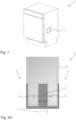
- a household appliance 1 is shown schematically, which can be designed, for example, as a dishwasher, as a washing machine or the like.
- the household appliance 1 comprises a sensor device 2, which is integrated in the household appliance 1. It is preferably provided that the sensor device 2 is at least partially in contact with a liquid 7, for example a cleaning water 7.
- a control unit 17 is also shown, to which the sensor signals can preferably be connected. By means of the control unit 17, it can be possible for the household appliance 1 to carry out actions depending on the measurement results or sensor signals or to be able to control the operation of the household appliance 1. Such actions can be, for example, error messages, acoustic signals, adjusting the washing program or communication with the smartphone via a wireless connection, such as WLAN, Bluetooth, or the like.
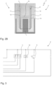
- the sensor device 2 is shown in more detail according to two embodiments, with certain components already being present, since the sensor device 2 is based on a turbidity sensor, so that additions to the sensor device 2 now present are necessary.
- the sensor device 2 has a light transmitter side 3 and a light receiver side 4.
- At least one light source 5 and at least one light receiver 6 are also provided. Light can be emitted by means of the light source 5.
- the light source 5 is an LED light source which can emit light with a certain wavelength or light with certain wavelengths.
- a section of the sensor device 2 is shown, with one or more light sources 5 arranged on the light transmitter side 3 and one or more light receivers 6 arranged on the light receiver side.
- Light can be emitted by means of the light source(s) 5 and received by means of the light receivers 6.
- the light is shown as an example as a light path L between the light source 5 and the light receiver 6.
- the light emitting side 3 and the light receiving side 4 are arranged at a distance from one another, i.e., at a distance 8 from one another.
- the sides 3, 4 are designed like fingers.
- a liquid 7 is provided between the light emitting side 3 and the light receiving side 4, so that the emitted light passes through the liquid 7 from the light emitting side 3 to the light receiving side 4.
- a housing 14 is provided in which the electronic components are located in order to seal them against the liquid 7.
- the sensor device 2 preferably comprises a light source 5 on the light transmitter side 3.
- the sensor device 2 has a light guide 11 with a first light guide element 12 and a second light guide element 13.
- the first light guide element 12 is preferably arranged on the light transmitter side 3 and the second light guide element 13 on the light receiver side 4.
- the light guide elements 12, 13 can preferably be connected to one another, for example by means of a connecting element 15. This can increase the stability of the light guide 11.
- the designs and embodiments of the Figure 2A also apply to the Figure 2B .
- the light, represented by the light path L, of the light source 5 is emitted to the first light guide element 12, transported by means of the first light guide element 12 and transmitted to a second light guide element 13. It is particularly preferred that the light guide elements 12, 13 are spaced apart from one another by a distance 8.
- the light is transmitted to one or more light receivers 6, wherein the light receiver 6 is designed to receive the light and output a corresponding sensor signal.
- the light passes through the liquid 7.
- the existing standard turbidity sensor design can be used, for example by providing a multi-chip LED which can emit the colors red, green and blue and/or white. In this way, the functionality for detecting the color of the liquid 7 can be subsequently integrated into the existing turbidity sensor.
- the light receiver 6 and the light source 5 can be connected to each other at least in terms of signaling, so that a change or deviation of the received sensor signal of the light receiver 6 is compared depending on the reference value present in the light source 5.
- the light arriving at the light receiver 6 is converted into an electrical quantity, for example a voltage, using a suitable circuit, whereby the electrical quantity, for example the voltage, can represent the output signal.
- the output signal for example a voltage
- the output signal can be used as a reference value for the reference state. Any deviation from the reference state produces a different measurement result or a different output signal, such as a voltage.
- the color of the liquid 7 can then be determined based on the absorption or attenuation of light or certain wavelengths of light.
- the sensor signal depends on the intensity or a non-absorbed part of the transmitted light.
- the light receiver 6 is designed as a phototransistor.
- the phototransistor is sensitive to the transmitted light, and when light hits the phototransistor, a photocurrent is generated by the photoelectric effect, which can be further processed into an output signal using a suitable electrical circuit.
- the output signal can be a voltage, for example, which is therefore dependent on the intensity of the light arriving at the receiver.
- one or more further light sources 16 can be provided, which can emit UV light and/or IR light, for example.
- the circuit can be adapted accordingly.
- the sensor device 2 can preferably be calibrated accordingly, whereby a calibration can be carried out, for example, with respect to a reference liquid.
- the reference liquid can particularly preferably be clear water or distilled water, so that the light received can be specified as the reference by means of the light receiver 6 and the corresponding sensor signal. If the emitted light is attenuated along the measuring path, the output signal changes depending on this attenuation. Conclusions can be drawn about the properties of the liquid, such as the color, from the deviation from the reference signal.
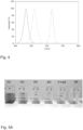
- the Figure 4 is shown as an example which colors can be emitted by means of one or more light sources 5. It is intended, as in the Figure 3 shown that the light source 5 is intended to emit at least three different colors, wherein more preferably the emitted colors are primary colors red, green and blue of the additive color mixture. According to the Figure 4 It is further provided where the respective wavelength ranges or the corresponding peak wavelength of the respective range can be located.
- the present system is calibrated or referenced with the sensor device 2 to distilled water. Additional samples are specified here, which are numbered accordingly or are marked. The color differences are in the Figure 5A can be clearly seen.
- the values output by the light receiver 6 with regard to the transmitted or transmitted colors red, green and blue are accordingly stored as 100%. Deviations in the output of the light receiver 6, i.e. the phototransistor, are accordingly indicated in smaller percentages. This can be seen, for example, in samples D3 and D2. It is also possible to see which of the colors red, green and blue are absorbed accordingly.
- these values are multiplied by the maximum value of the additive color space, whereby this value is 255.
- the value obtained i.e. the multiplied value of the 255 value times the respective percentage, gives the respective value in the additive color space. This is done with each of the colors red, green, blue, so that the respective color tone of the additive color space can be determined by combining the three multiplication values. As can be seen from the comparison of the colors of the Figures 5A and 5B can be seen, the calculation or determination is very accurate.
- Section A of the Figure 5B The respective measured values and the reference value are shown.
- section B of the Figure 5B the relationship between the respective measured value and the reference value is shown.
- section C shows the respective calculated value of the additive color space, by means of which the color in the additive color space can be determined.
- a single light receiver 6 is provided.
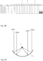
- a light guide element 9 is provided, wherein the light guide element 9 is intended and designed to redirect light in such a way that it is focused on a single point.
- This light guide element 9 is particularly preferably in the Figure 6A , where the light guide element 9 is a parabolic element or curved surface 10.
- the designations LED1 to LED4 are shown for different outputs or light emissions of the light source 5, which can correspond, for example, to the colors red, green, blue and an infrared light source.
- a single light source 5 is provided, which is provided for example as a broadband light source, for example a white-colored LED, which can be divided by means of the light guide element 9 or the parabolic element 10, which can output the respective light signal to correspondingly designed phototransistors, wherein preferably the phototransistors are designed in such a way that they are only sensitive to a certain wavelength range or corresponding filters are arranged on the light guide element 9 and the phototransistor, which can filter the light from the light source 5.
- the filters can also be arranged in the respective light receiver.
- a sensor device 2 with the light guide element 10 is in the Figures 7A to 7D shown.
- Several light sources 5 are shown with a single light receiver 6.
- several light receivers 6 are shown with a single light source 5.
- At least two light sources 5, 5', 5" are shown, each of which is assigned to a first or second light path L', L".
- the transmission of the light from the light source 5, 5', 5" to the light receiver 6 has already been shown.
- the light guide element 9 is now additionally arranged, which focuses the light paths L', L" on a point at which the light receiver 6 is arranged.
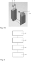
- step S1 a corresponding household appliance 1 is provided which has the sensor device 2 according to the invention.
- step S2 light is emitted by means of the light source 5 and preferably transmitted to the light receiver 6 via the light guides 3, 4.
- step S3 the light is received by means of the light receiver 6 and a corresponding sensor signal is received from the light receiver 6.
- these sensor signals are combined with one another and the color of the cleaning water 7 is determined from the combination of the sensor signals.
Landscapes
- Physics & Mathematics (AREA)
- Spectroscopy & Molecular Physics (AREA)
- General Physics & Mathematics (AREA)
- Chemical & Material Sciences (AREA)
- Pathology (AREA)
- Analytical Chemistry (AREA)
- Biochemistry (AREA)
- General Health & Medical Sciences (AREA)
- Health & Medical Sciences (AREA)
- Immunology (AREA)
- Life Sciences & Earth Sciences (AREA)
- Engineering & Computer Science (AREA)
- Textile Engineering (AREA)
- Electromagnetism (AREA)
- Computer Networks & Wireless Communication (AREA)
- Signal Processing (AREA)
- Investigating Or Analysing Materials By Optical Means (AREA)
- Spectrometry And Color Measurement (AREA)
Applications Claiming Priority (1)
| Application Number | Priority Date | Filing Date | Title |
|---|---|---|---|
| DE102023117402.9A DE102023117402A1 (de) | 2023-06-30 | 2023-06-30 | Haushaltsgerät mit einer Sensorvorrichtung |
Publications (1)
| Publication Number | Publication Date |
|---|---|
| EP4484926A1 true EP4484926A1 (fr) | 2025-01-01 |
Family
ID=91185403
Family Applications (1)
| Application Number | Title | Priority Date | Filing Date |
|---|---|---|---|
| EP24176714.4A Withdrawn EP4484926A1 (fr) | 2023-06-30 | 2024-05-17 | Appareil ménager doté d'un dispositif de détection |
Country Status (4)
| Country | Link |
|---|---|
| US (1) | US20250003132A1 (fr) |
| EP (1) | EP4484926A1 (fr) |
| CN (1) | CN119223897A (fr) |
| DE (1) | DE102023117402A1 (fr) |
Families Citing this family (1)
| Publication number | Priority date | Publication date | Assignee | Title |
|---|---|---|---|---|
| DE102024114509A1 (de) * | 2024-05-23 | 2025-11-27 | Emz-Hanauer Gmbh & Co. Kgaa | Haushaltsgerät mit einer Sensorvorrichtung |
Citations (9)
| Publication number | Priority date | Publication date | Assignee | Title |
|---|---|---|---|---|
| EP0823628A2 (fr) * | 1996-08-06 | 1998-02-11 | AEG Hausgeräte GmbH | Capteur optique |
| US7246396B2 (en) * | 2001-07-19 | 2007-07-24 | Bsh Bosch Und Siemens Hausgeraete Gmbh | Process for operating a water-bearing domestic appliance and domestic appliance for same |
| US20070299545A1 (en) * | 2006-06-22 | 2007-12-27 | Kavita Agrawal | Control of washing machines using color sensors |
| US20120120386A1 (en) * | 2010-11-15 | 2012-05-17 | General Electric Company | Water color sensing hardware and methodology for appliances |
| CN106012430A (zh) * | 2016-07-05 | 2016-10-12 | 海信(山东)冰箱有限公司 | 一种颜色传感器及洗衣机 |
| US20200277721A1 (en) * | 2017-09-11 | 2020-09-03 | Samsung Electronics Co., Ltd. | Washing machine and control method therefor |
| DE102019002447B3 (de) * | 2019-04-03 | 2020-09-24 | Emz-Hanauer Gmbh & Co. Kgaa | Haushalts-Wäschewaschgerät oder Geschirrspüler und optischer Sensor hierfür |
| US20220056627A1 (en) * | 2018-12-24 | 2022-02-24 | Samsung Electronics Co., Ltd. | Washing machine and method of controlling the same |
| DE102021126051B3 (de) * | 2021-10-07 | 2023-03-23 | Emz-Hanauer Gmbh & Co. Kgaa | Vorrichtung, Haushaltsgerät und Verfahren zur Erkennung von Stoffgruppen in einem Fluid innerhalb eines Haushaltsgerätes sowie Verfahren zur Anpassung eines Reinigungsprozesses eines wasserführenden Haushaltsgerätes |
-
2023
- 2023-06-30 DE DE102023117402.9A patent/DE102023117402A1/de not_active Withdrawn
-
2024
- 2024-05-17 EP EP24176714.4A patent/EP4484926A1/fr not_active Withdrawn
- 2024-06-05 US US18/734,066 patent/US20250003132A1/en active Pending
- 2024-06-06 CN CN202410730816.3A patent/CN119223897A/zh active Pending
Patent Citations (9)
| Publication number | Priority date | Publication date | Assignee | Title |
|---|---|---|---|---|
| EP0823628A2 (fr) * | 1996-08-06 | 1998-02-11 | AEG Hausgeräte GmbH | Capteur optique |
| US7246396B2 (en) * | 2001-07-19 | 2007-07-24 | Bsh Bosch Und Siemens Hausgeraete Gmbh | Process for operating a water-bearing domestic appliance and domestic appliance for same |
| US20070299545A1 (en) * | 2006-06-22 | 2007-12-27 | Kavita Agrawal | Control of washing machines using color sensors |
| US20120120386A1 (en) * | 2010-11-15 | 2012-05-17 | General Electric Company | Water color sensing hardware and methodology for appliances |
| CN106012430A (zh) * | 2016-07-05 | 2016-10-12 | 海信(山东)冰箱有限公司 | 一种颜色传感器及洗衣机 |
| US20200277721A1 (en) * | 2017-09-11 | 2020-09-03 | Samsung Electronics Co., Ltd. | Washing machine and control method therefor |
| US20220056627A1 (en) * | 2018-12-24 | 2022-02-24 | Samsung Electronics Co., Ltd. | Washing machine and method of controlling the same |
| DE102019002447B3 (de) * | 2019-04-03 | 2020-09-24 | Emz-Hanauer Gmbh & Co. Kgaa | Haushalts-Wäschewaschgerät oder Geschirrspüler und optischer Sensor hierfür |
| DE102021126051B3 (de) * | 2021-10-07 | 2023-03-23 | Emz-Hanauer Gmbh & Co. Kgaa | Vorrichtung, Haushaltsgerät und Verfahren zur Erkennung von Stoffgruppen in einem Fluid innerhalb eines Haushaltsgerätes sowie Verfahren zur Anpassung eines Reinigungsprozesses eines wasserführenden Haushaltsgerätes |
Also Published As
| Publication number | Publication date |
|---|---|
| US20250003132A1 (en) | 2025-01-02 |
| DE102023117402A1 (de) | 2025-01-02 |
| CN119223897A (zh) | 2024-12-31 |
Similar Documents
| Publication | Publication Date | Title |
|---|---|---|
| DE60013258T2 (de) | Faseroptischer sensor mit photochromatischem wandler und methode zu seiner anwendung | |
| DE102015103139B3 (de) | Verteilte optische Messvorrichtungen und Verfahren zum Ausführen einer Messung | |
| EP1655599B1 (fr) | Détecteur de fil | |
| EP2418315A2 (fr) | Appareil ménager doté d'un capteur de niveau de remplissage et procédé de détermination d'un paramètre d'état dans un appareil ménager | |
| DE102010037676B4 (de) | Verfahren zur Verfolgung der Farbhomogenität der Garnoberfläche und Vorrichtung zu dessen Durchführung | |
| EP4484926A1 (fr) | Appareil ménager doté d'un dispositif de détection | |
| EP1410002B1 (fr) | Procede pour identifier des corps etrangers dans un materiau textile | |
| EP3270045B1 (fr) | Systeme de mesure de concentrations de gaz | |
| WO2022198342A1 (fr) | Détection du rapport de mélange de deux composants d'une structure fibreuse textile | |
| DE112016002217T5 (de) | Abtastendoskopsystem | |
| DE10257238B4 (de) | Verfahren und Vorrichtung zur Charakterisierung von Verunreinigungen in Flüssigkeiten | |
| DE102007028117A1 (de) | Verfahren und optischer Sensor zum Nachweis von Objekten im Bereich einer sicherheitsmäßig zu überwachenden Einrichtung, Computerprogramm und Computerprogrammprodukt | |
| DE10360563A1 (de) | Verfahren und Vorrichtung zur Bestimmung des Verunreinigungszustands von Flüssigkeiten | |
| DE19806560B4 (de) | Verfahren und Vorrichtung zum Waschen und/oder Spülen von Wäsche in Waschmaschinen bzw. Waschtrocknern | |
| DE102024114509A1 (de) | Haushaltsgerät mit einer Sensorvorrichtung | |
| EP1595137B1 (fr) | Procede et dispositifs permettant de determiner et surveiller des etats d'impuretes dans differents fluides | |
| WO2019030041A1 (fr) | Procédé pour fournir un signal de détection pour des objets à détecter | |
| DE202007008540U1 (de) | Optischer Sensor zum Nachweis von Objekten im Bereich einer sicherheitsmäßig zu überwachenden Einrichtung | |
| DE102017209748B4 (de) | Verfahren zur Bereitstellung eines Detektionssignals für zu detektierende Objekte | |
| WO2000005555A1 (fr) | Procede de controle de l'aptitude au fonctionnement d'un spectrometre, et spectrometre pourvu d'un dispositif de reconnaissance de defauts | |
| DE2823514A1 (de) | Spektralapparat | |
| DE102014105312B3 (de) | Erfassungsvorrichtung | |
| CH720486A1 (de) | Untersuchung eines zwei Bestandteile enthaltenden textilen Fasergebildes | |
| EP3887798A1 (fr) | Dispositif spectromètre et procédé correspondant pour faire fonctionner un dispositif spectromètre | |
| WO2024031201A1 (fr) | Étude d'une structure de fibres textiles contenant deux composants |
Legal Events
| Date | Code | Title | Description |
|---|---|---|---|
| PUAI | Public reference made under article 153(3) epc to a published international application that has entered the european phase |
Free format text: ORIGINAL CODE: 0009012 |
|
| STAA | Information on the status of an ep patent application or granted ep patent |
Free format text: STATUS: THE APPLICATION HAS BEEN PUBLISHED |
|
| AK | Designated contracting states |
Kind code of ref document: A1 Designated state(s): AL AT BE BG CH CY CZ DE DK EE ES FI FR GB GR HR HU IE IS IT LI LT LU LV MC ME MK MT NL NO PL PT RO RS SE SI SK SM TR |
|
| STAA | Information on the status of an ep patent application or granted ep patent |
Free format text: STATUS: THE APPLICATION IS DEEMED TO BE WITHDRAWN |
|
| 18D | Application deemed to be withdrawn |
Effective date: 20250702 |