EP2418343A2 - Öffnungsbegrenzer - Google Patents
Öffnungsbegrenzer Download PDFInfo
- Publication number
- EP2418343A2 EP2418343A2 EP11177283A EP11177283A EP2418343A2 EP 2418343 A2 EP2418343 A2 EP 2418343A2 EP 11177283 A EP11177283 A EP 11177283A EP 11177283 A EP11177283 A EP 11177283A EP 2418343 A2 EP2418343 A2 EP 2418343A2
- Authority
- EP
- European Patent Office
- Prior art keywords
- opening
- body portion
- securing
- restrictor
- connecting means
- Prior art date
- Legal status (The legal status is an assumption and is not a legal conclusion. Google has not performed a legal analysis and makes no representation as to the accuracy of the status listed.)
- Granted
Links
Images


Classifications
-
- E—FIXED CONSTRUCTIONS
- E05—LOCKS; KEYS; WINDOW OR DOOR FITTINGS; SAFES
- E05C—BOLTS OR FASTENING DEVICES FOR WINGS, SPECIALLY FOR DOORS OR WINDOWS
- E05C17/00—Devices for holding wings open; Devices for limiting opening of wings or for holding wings open by a movable member extending between frame and wing; Braking devices, stops or buffers, combined therewith
- E05C17/02—Devices for holding wings open; Devices for limiting opening of wings or for holding wings open by a movable member extending between frame and wing; Braking devices, stops or buffers, combined therewith by mechanical means
- E05C17/04—Devices for holding wings open; Devices for limiting opening of wings or for holding wings open by a movable member extending between frame and wing; Braking devices, stops or buffers, combined therewith by mechanical means with a movable bar or equivalent member extending between frame and wing
- E05C17/36—Devices for holding wings open; Devices for limiting opening of wings or for holding wings open by a movable member extending between frame and wing; Braking devices, stops or buffers, combined therewith by mechanical means with a movable bar or equivalent member extending between frame and wing comprising a flexible member, e.g. chains
- E05C17/365—Security chains
Definitions
- This invention relates to an opening restrictor which may be used, for example, to restrict the degree to which a window or a door can be opened.
- the restrictor may be used in other applications where the opening of a substantially planar closure is to be restricted.
- Window restrictors are used to restrict the degree to which a window can be opened in order to prevent persons falling through the window opening. Such window restrictors are generally releasable, or otherwise constructed, in order to allow the window to be opened fully when required, for example for cleaning purposes.
- a problem with known window restrictors is that they are mounted separately from other window furniture which increases overall cost, increases the number of fixing holes that require to be drilled in the window and/or its frame, and also detracts from the appearance of the window and its furniture.
- an opening restrictor comprising a body portion, a securing means and connecting means secured to the securing means and adapted to be releasably secured to the body portion, the body portion being adapted to be secured to a frame of an opening and including releasable locking means for releasably securing the connecting means to the body portion, and the securing means being adapted to be secured to an opening member mounted to the frame between the opening member and means for controlling opening and closing of the opening member, whereby opening of the opening member is restricted when the connecting means is secured to the body portion and is unrestricted when the connecting means is released from the body portion.
- the securing means may comprise a substantially planar elongate portion adapted to be mounted between the opening member and the means for controlling opening and closing of the opening member, the elongate portion being provided with apertures for the passage of fastening means for the controlling means, and with a portion adapted to extend away from the opening member, for example substantially at right angles thereto, for securing an end of the connecting means.
- the connecting means may comprise a flexible cable, for example of coated wire.
- the connecting means may be provided at that end region thereof that is releasably secured to the body portion with a profiled portion, for example in the form of an annular recess formed around the periphery of the connecting means, for releasably engaging with the body portion.
- the connecting means may be provided at that end thereof that is releasably secured to the body portion with a rounded end portion to facilitate insertion of the end of the connecting means into the body portion.
- the body portion may include a securing lever pivotably mounted within the body portion and having an end which is movable between a first position in which the connecting means is secured within an opening in the body portion and a second position in which the connecting means can be withdrawn from the body portion.
- An end portion of the securing lever may be chamfered to facilitate insertion of the connecting means into the body portion.
- Biasing means may be provided for biasing the securing lever to the first position.
- the biasing means may comprise a tongue of resilient material extending from a supporting sheet, the tongue engaging with the securing lever.
- the biasing means may be mounted within the body portion by means of screw fasteners.
- the screw fasteners may be in hollow cylindrical form and may be secured in openings passing through the body portion, whereby fastenings for securing the body portion to the frame are able to pass through the openings and through the hollow cylindrical screw fasteners.
- a base plate may be provided between the biasing means and the hollow cylindrical screw fasteners.
- the locking means may be movable in its unlocked condition so as to urge the securing lever against the biasing means so as to move the securing lever to its second position.
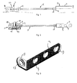
- Figure 1 is a view of one embodiment of an opening restrictor according to the present invention.
- Figure 2 is a sectional view taken along the line II-II of the opening restrictor shown in Figure 1 ;
- Figure 3 is a perspective view of a securing bracket forming part of an opening restrictor according to the present invention.
- Figure 4 is a perspective view of a modified securing bracket forming part of an opening restrictor according to the present invention.
- Figure 5 is a cross-sectional view of a plug for use with a cable forming part of an opening restrictor according to the present invention
- Figure 6 is a sectional view of a body forming part of an opening restrictor according to the present invention.
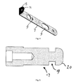
- Figure 7 is a perspective view of a securing lever forming part of an opening restrictor according to the present invention.
- Figure 8 is a perspective view of a biasing spring forming part of an opening restrictor according to the present invention.
- Figure 9 is a plan view of a back plate forming part of an opening restrictor according to the present invention.
- Figure 10 is an elevational view of a hollow cylindrical fastener forming part of an opening restrictor according to the present invention.
- Figure 11 is a perspective view of an alternative embodiment of the securing lever shown in Figure 7 .
- the opening restrictor shown in Figures 1 and 2 comprises a body portion 1 which is releasably connected to a securing bracket 3 by way of a connecting means 5, for example in the form of a cable.
- the securing bracket 3 as illustrated comprises a window handle bracket which is secured to an opening window (not shown), although a bracket in the form of a door handle plate can be used with a door.
- the securing bracket 3 is made, for example, of stainless steel and includes a substantially planar elongate portion 7 which in use is positioned between an opening member, such as a door or window, and a conventional means, such as a window handle or a door handle, for controlling opening and closing of the opening member.
- the elongate portion of the securing bracket is provided with apertures 9 to allow the passage of fasteners provided for the window or door handle.
- the securing bracket 3 also includes a portion 11 which extends in a direction away from the opening member, for example substantially at right angles as illustrated. The portion 11 is attached to the elongate portion 7 and is provided with an aperture 13 (shown more clearly in Figure 3 ).
- An alternative configuration of securing bracket, for example for use with a door handle mounting, is shown in Figure 4 .
- the cable 5 may include a length of conventional flexible steel cable provided with a covering of plastics material.
- a plug 15 is secured, for example by crimping, to one end of the length of cable and may be made, for example, of stainless steel. The plug 15 is then made captive through the aperture 13 in the bracket portion 11. Ideally, in use the head of the plug 15 is positioned close to part of the opening control means, ideally a non-moving part thereof, so as to restrict access to the plug 15 to minimise the likelihood of tampering.
- a further plug 17 is secured to the other end of the length of cable, for example by crimping, for releasably securing to the body portion 1.
- the further plug 17, shown in detail in Figure 5 is formed with a profiled portion 19 and a rounded end 20, which enable the further plug 17 to be releasably secured to the body portion.
- the profiled portion 19 comprises an annular recess formed around the periphery of the plug 17.
- the body portion 1 includes a body 21 (shown in more detail in Figure 6 ), for example of die-cast aluminium, into which a lock 23 is secured.
- the body 21 is formed with two openings 25, 27 for receiving conventional fasteners (not shown) for securing the body portion 1 to a frame of an opening, such as a window frame or door frame, for example.
- the outer ends of the openings 25, 27 are provided with caps 29, 31, for example of Nylon, which are ideally profiled to match the profile of the body 21.
- the caps 29, 31 inhibit access to the fasteners and prevent tampering therewith.
- the body 21 is also formed with a lateral opening 33 dimensioned to receive the further plug 17 of the cable 5.
- a securing lever 35 is pivotally mounted within the body 21 and extends across an opening 37 in which the lock 23 is received.
- the securing lever is formed with an aperture 39 in one end region thereof for mounting the lever in a pivotable manner by way on a securing pin 41, and is formed at the other end thereof with an engaging portion 43 for engaging with the profiled portion 19 of the further plug 17.
- An outer edge of the engaging portion 43 is formed with a chamfer 45 such that insertion of the rounded end 20 of the further plug 17 causes the lever 35 to pivot from a first position to a second position and to allow the plug 17 into the lateral opening 33.
- the lever 35 then returns to the first position under the influence of a biasing spring 47 so as to lock the further plug in the body portion 1.
- FIG. 11 An alternative securing lever is shown in Figure 11 and functions in essentially the same manner as the securing lever of Figure 7 .
- the biasing spring 47 is shown in more detail in Figure 8 and comprises a sheet 49 of resilient material, such as spring steel, formed with a tongue 51 at an angle to the remainder of the sheet and directed towards the securing lever 35 so as to bias the engaging portion 43 into the profiled portion 19 of the further plug 17.
- the biasing spring 47 is maintained in position in the body 21 by means of a back plate 53 (shown in Figure 9 ) which is secured in place by two hollow cylindrical screw fasteners 55 (shown in Figure 10 ) which engage in the openings 25, 27, while allowing screw fasteners for securing the body portion 1 to pass therethrough.
- a key (not shown) is used to unlock the lock 23.
- a body of the lock can be depressed into the body 21 and is biased to return to an extended position.
- the lever 35 is pivoted to displace the engaging portion 43 out of the lateral opening 33 so as to disengage from the profiled portion 19 of the further plug 17.
- This allows the further plug 17 to be released from the body portion 1 and allows the window, door or the like to be opened fully.
- the body of the lock cannot be depressed into the body 21 and the further plug 17, if present in the lateral opening 33, cannot be removed, therefore restricting opening of the window, door or the like.
- the window, door or the like can be opened in an unrestricted manner.
- the further plug 17 can be inserted into the lateral opening 33 irrespective of whether the lock 23 is in its locked or unlocked configuration.
- the rounded end 20 of the further plug 17 contacts the chamfer 45 of the engaging portion 43 of the securing lever 35 and pivots the securing lever 35 to allow the further plug 17 to enter the lateral opening 33 until the engaging portion 43 engages with the profiled portion 19 to retain the further plug in the lateral opening.
- the lock 23 is in its unlocked configuration the lock body can be depressed to release the further plug 17, but if key has been used to move the lock to its locked configuration the lock body cannot be depressed and the further plug 17, and therefore the cable 5, is locked to the body portion 1.
Landscapes
- Engineering & Computer Science (AREA)
- Mechanical Engineering (AREA)
- Lock And Its Accessories (AREA)
- Connector Housings Or Holding Contact Members (AREA)
Applications Claiming Priority (1)
| Application Number | Priority Date | Filing Date | Title |
|---|---|---|---|
| GBGB1013582.0A GB201013582D0 (en) | 2010-08-13 | 2010-08-13 | Opening restrictor |
Publications (4)
| Publication Number | Publication Date |
|---|---|
| EP2418343A2 true EP2418343A2 (de) | 2012-02-15 |
| EP2418343A3 EP2418343A3 (de) | 2015-03-25 |
| EP2418343B1 EP2418343B1 (de) | 2016-09-21 |
| EP2418343B2 EP2418343B2 (de) | 2019-02-20 |
Family
ID=42937920
Family Applications (1)
| Application Number | Title | Priority Date | Filing Date |
|---|---|---|---|
| EP11177283.6A Not-in-force EP2418343B2 (de) | 2010-08-13 | 2011-08-11 | Öffnungsbegrenzer |
Country Status (2)
| Country | Link |
|---|---|
| EP (1) | EP2418343B2 (de) |
| GB (1) | GB201013582D0 (de) |
Cited By (8)
| Publication number | Priority date | Publication date | Assignee | Title |
|---|---|---|---|---|
| WO2014108680A1 (en) * | 2013-01-09 | 2014-07-17 | The Jackloc Company Limited | Cable restrictor with a lockable body for a door or a window |
| EP3034729A1 (de) | 2014-12-17 | 2016-06-22 | Andrew John Lane | Notöffnungsanordnung |
| EP3228789A1 (de) | 2016-04-08 | 2017-10-11 | J. Banks & Co. Limited | Kabeldrossel |
| GB2549527A (en) * | 2016-04-22 | 2017-10-25 | New Star Door Controls Ltd | Restrictor |
| EP2733289A3 (de) * | 2012-11-20 | 2017-12-27 | J. Banks & Co. Limited | Öffnungsbegrenzer und Teilersatz zur Montage eines Begrenzers |
| WO2019161973A1 (en) * | 2018-02-23 | 2019-08-29 | Uap Limited | A restrictor for a window or a door |
| US11060330B2 (en) * | 2018-05-15 | 2021-07-13 | Elbee Pty Ltd. | Tether lock |
| USD938257S1 (en) | 2018-05-15 | 2021-12-14 | Elbee Pty Ltd. | Lock |
Families Citing this family (2)
| Publication number | Priority date | Publication date | Assignee | Title |
|---|---|---|---|---|
| EP3856621B1 (de) | 2018-09-28 | 2025-09-17 | Razor USA LLC | Roller mit lenksperre |
| CN214607799U (zh) * | 2020-12-10 | 2021-11-05 | 美国锐哲有限公司 | 一种用于滑板车的车锁机构 |
Family Cites Families (6)
| Publication number | Priority date | Publication date | Assignee | Title |
|---|---|---|---|---|
| GB354647A (en) * | 1930-11-10 | 1931-08-13 | Martin Samson | Safety arrangement for doors of dwellings |
| US3640106A (en) * | 1970-10-12 | 1972-02-08 | Wessel Hardware Corp | Key-operated chain door-lock construction |
| US4027908A (en) * | 1975-07-25 | 1977-06-07 | International Top Security Corporation | Safety chain lock for doors |
| FI64835C (fi) * | 1978-04-27 | 1984-01-10 | Yrjoe Teodor Laine | Saekerhetsanordning foer doerrar foenster och liknande |
| DE3614031C2 (de) * | 1986-04-25 | 1994-02-03 | Melchert Beschlaege | Beschlag mit Kette zur Sicherung spaltoffener Türen |
| GB2414509A (en) * | 2004-05-24 | 2005-11-30 | Stuart Rennie | Door lock with key-releasable ecurity chain |
-
2010
- 2010-08-13 GB GBGB1013582.0A patent/GB201013582D0/en not_active Ceased
-
2011
- 2011-08-11 EP EP11177283.6A patent/EP2418343B2/de not_active Not-in-force
Non-Patent Citations (1)
| Title |
|---|
| None |
Cited By (12)
| Publication number | Priority date | Publication date | Assignee | Title |
|---|---|---|---|---|
| EP2733289A3 (de) * | 2012-11-20 | 2017-12-27 | J. Banks & Co. Limited | Öffnungsbegrenzer und Teilersatz zur Montage eines Begrenzers |
| WO2014108680A1 (en) * | 2013-01-09 | 2014-07-17 | The Jackloc Company Limited | Cable restrictor with a lockable body for a door or a window |
| EP3034729A1 (de) | 2014-12-17 | 2016-06-22 | Andrew John Lane | Notöffnungsanordnung |
| EP3228789A1 (de) | 2016-04-08 | 2017-10-11 | J. Banks & Co. Limited | Kabeldrossel |
| GB2551015A (en) * | 2016-04-08 | 2017-12-06 | J Banks & Co Ltd | Cable restrictor |
| GB2551015B (en) * | 2016-04-08 | 2021-02-10 | J Banks & Co Ltd | Cable restrictor |
| GB2549527A (en) * | 2016-04-22 | 2017-10-25 | New Star Door Controls Ltd | Restrictor |
| WO2019161973A1 (en) * | 2018-02-23 | 2019-08-29 | Uap Limited | A restrictor for a window or a door |
| GB2586378A (en) * | 2018-02-23 | 2021-02-17 | Uap Ltd | A restrictor for a window or a door |
| GB2586378B (en) * | 2018-02-23 | 2023-01-04 | Uap Ltd | A restrictor for a window or a door |
| US11060330B2 (en) * | 2018-05-15 | 2021-07-13 | Elbee Pty Ltd. | Tether lock |
| USD938257S1 (en) | 2018-05-15 | 2021-12-14 | Elbee Pty Ltd. | Lock |
Also Published As
| Publication number | Publication date |
|---|---|
| GB201013582D0 (en) | 2010-09-29 |
| EP2418343A3 (de) | 2015-03-25 |
| EP2418343B1 (de) | 2016-09-21 |
| EP2418343B2 (de) | 2019-02-20 |
Similar Documents
| Publication | Publication Date | Title |
|---|---|---|
| EP2418343A2 (de) | Öffnungsbegrenzer | |
| US8851535B2 (en) | Security device for a double door | |
| US6993944B2 (en) | Dead bolt lock | |
| US7418845B2 (en) | Two-point mortise lock | |
| US8056943B2 (en) | Full width overlay drawer latch | |
| US20110232029A1 (en) | Adjustable locking device for windows and doors | |
| EP2480739B1 (de) | Befestigungsanordnung für einen türgriff | |
| US20090107865A1 (en) | Safety enhanced pistol holder | |
| US9644395B2 (en) | Deadbolt knob security device | |
| US10156085B2 (en) | Restraint resistant handle | |
| US7374213B2 (en) | Security door stop | |
| US10865593B2 (en) | Door guard assembly | |
| US6893007B2 (en) | Safety fence | |
| US7452011B1 (en) | Safety latch apparatus | |
| US20180320415A1 (en) | Fence gate latch assembly | |
| AU2022201242A1 (en) | Pivot block | |
| US20180163445A1 (en) | Security Latch for a Swing Bar Door Guard | |
| CN203654892U (zh) | 弹射栓组件以及双向长插销锁定机构 | |
| US8881561B2 (en) | Security device for a window handle or door handle | |
| US6454323B1 (en) | High-security auxiliary door lock | |
| EP3351713A1 (de) | Türbegrenzer | |
| US4079973A (en) | Adjustable chain door guard | |
| US20090183658A1 (en) | Vault cover with vault door and spring-biased support arm | |
| AU703274B2 (en) | A striker | |
| US20070096478A1 (en) | Security devices |
Legal Events
| Date | Code | Title | Description |
|---|---|---|---|
| AK | Designated contracting states |
Kind code of ref document: A2 Designated state(s): AL AT BE BG CH CY CZ DE DK EE ES FI FR GB GR HR HU IE IS IT LI LT LU LV MC MK MT NL NO PL PT RO RS SE SI SK SM TR |
|
| AX | Request for extension of the european patent |
Extension state: BA ME |
|
| PUAI | Public reference made under article 153(3) epc to a published international application that has entered the european phase |
Free format text: ORIGINAL CODE: 0009012 |
|
| PUAL | Search report despatched |
Free format text: ORIGINAL CODE: 0009013 |
|
| AK | Designated contracting states |
Kind code of ref document: A3 Designated state(s): AL AT BE BG CH CY CZ DE DK EE ES FI FR GB GR HR HU IE IS IT LI LT LU LV MC MK MT NL NO PL PT RO RS SE SI SK SM TR |
|
| AX | Request for extension of the european patent |
Extension state: BA ME |
|
| RIC1 | Information provided on ipc code assigned before grant |
Ipc: E05C 17/36 20060101AFI20150213BHEP |
|
| 17P | Request for examination filed |
Effective date: 20150925 |
|
| RBV | Designated contracting states (corrected) |
Designated state(s): AL AT BE BG CH CY CZ DE DK EE ES FI FR GB GR HR HU IE IS IT LI LT LU LV MC MK MT NL NO PL PT RO RS SE SI SK SM TR |
|
| GRAP | Despatch of communication of intention to grant a patent |
Free format text: ORIGINAL CODE: EPIDOSNIGR1 |
|
| INTG | Intention to grant announced |
Effective date: 20160513 |
|
| GRAS | Grant fee paid |
Free format text: ORIGINAL CODE: EPIDOSNIGR3 |
|
| GRAA | (expected) grant |
Free format text: ORIGINAL CODE: 0009210 |
|
| AK | Designated contracting states |
Kind code of ref document: B1 Designated state(s): AL AT BE BG CH CY CZ DE DK EE ES FI FR GB GR HR HU IE IS IT LI LT LU LV MC MK MT NL NO PL PT RO RS SE SI SK SM TR |
|
| REG | Reference to a national code |
Ref country code: GB Ref legal event code: FG4D |
|
| REG | Reference to a national code |
Ref country code: CH Ref legal event code: EP |
|
| REG | Reference to a national code |
Ref country code: AT Ref legal event code: REF Ref document number: 831211 Country of ref document: AT Kind code of ref document: T Effective date: 20161015 |
|
| REG | Reference to a national code |
Ref country code: IE Ref legal event code: FG4D |
|
| REG | Reference to a national code |
Ref country code: DE Ref legal event code: R096 Ref document number: 602011030511 Country of ref document: DE |
|
| REG | Reference to a national code |
Ref country code: NL Ref legal event code: FP |
|
| REG | Reference to a national code |
Ref country code: LT Ref legal event code: MG4D |
|
| REG | Reference to a national code |
Ref country code: DE Ref legal event code: R055 Ref document number: 602011030511 Country of ref document: DE |
|
| PG25 | Lapsed in a contracting state [announced via postgrant information from national office to epo] |
Ref country code: LT Free format text: LAPSE BECAUSE OF FAILURE TO SUBMIT A TRANSLATION OF THE DESCRIPTION OR TO PAY THE FEE WITHIN THE PRESCRIBED TIME-LIMIT Effective date: 20160921 Ref country code: RS Free format text: LAPSE BECAUSE OF FAILURE TO SUBMIT A TRANSLATION OF THE DESCRIPTION OR TO PAY THE FEE WITHIN THE PRESCRIBED TIME-LIMIT Effective date: 20160921 Ref country code: NO Free format text: LAPSE BECAUSE OF FAILURE TO SUBMIT A TRANSLATION OF THE DESCRIPTION OR TO PAY THE FEE WITHIN THE PRESCRIBED TIME-LIMIT Effective date: 20161221 Ref country code: FI Free format text: LAPSE BECAUSE OF FAILURE TO SUBMIT A TRANSLATION OF THE DESCRIPTION OR TO PAY THE FEE WITHIN THE PRESCRIBED TIME-LIMIT Effective date: 20160921 |
|
| PLCP | Request for limitation filed |
Free format text: ORIGINAL CODE: EPIDOSNLIM1 |
|
| PLCQ | Request for limitation of patent found admissible |
Free format text: ORIGINAL CODE: 0009231 |
|
| REG | Reference to a national code |
Ref country code: AT Ref legal event code: MK05 Ref document number: 831211 Country of ref document: AT Kind code of ref document: T Effective date: 20160921 |
|
| PG25 | Lapsed in a contracting state [announced via postgrant information from national office to epo] |
Ref country code: SE Free format text: LAPSE BECAUSE OF FAILURE TO SUBMIT A TRANSLATION OF THE DESCRIPTION OR TO PAY THE FEE WITHIN THE PRESCRIBED TIME-LIMIT Effective date: 20160921 Ref country code: GR Free format text: LAPSE BECAUSE OF FAILURE TO SUBMIT A TRANSLATION OF THE DESCRIPTION OR TO PAY THE FEE WITHIN THE PRESCRIBED TIME-LIMIT Effective date: 20161222 Ref country code: LV Free format text: LAPSE BECAUSE OF FAILURE TO SUBMIT A TRANSLATION OF THE DESCRIPTION OR TO PAY THE FEE WITHIN THE PRESCRIBED TIME-LIMIT Effective date: 20160921 |
|
| LIM1 | Request for limitation found admissible |
Free format text: SEQUENCE NO: 1; FILED DURING OPPOSITION PERIOD Filing date: 20170126 Effective date: 20170126 |
|
| PG25 | Lapsed in a contracting state [announced via postgrant information from national office to epo] |
Ref country code: RO Free format text: LAPSE BECAUSE OF FAILURE TO SUBMIT A TRANSLATION OF THE DESCRIPTION OR TO PAY THE FEE WITHIN THE PRESCRIBED TIME-LIMIT Effective date: 20160921 Ref country code: EE Free format text: LAPSE BECAUSE OF FAILURE TO SUBMIT A TRANSLATION OF THE DESCRIPTION OR TO PAY THE FEE WITHIN THE PRESCRIBED TIME-LIMIT Effective date: 20160921 |
|
| REG | Reference to a national code |
Ref country code: DE Ref legal event code: R026 Ref document number: 602011030511 Country of ref document: DE |
|
| PLBV | Information modified related to decision on request for limitation of patent |
Free format text: ORIGINAL CODE: 0009299LIMP |
|
| PLBI | Opposition filed |
Free format text: ORIGINAL CODE: 0009260 |
|
| PG25 | Lapsed in a contracting state [announced via postgrant information from national office to epo] |
Ref country code: ES Free format text: LAPSE BECAUSE OF FAILURE TO SUBMIT A TRANSLATION OF THE DESCRIPTION OR TO PAY THE FEE WITHIN THE PRESCRIBED TIME-LIMIT Effective date: 20160921 Ref country code: AT Free format text: LAPSE BECAUSE OF FAILURE TO SUBMIT A TRANSLATION OF THE DESCRIPTION OR TO PAY THE FEE WITHIN THE PRESCRIBED TIME-LIMIT Effective date: 20160921 Ref country code: SK Free format text: LAPSE BECAUSE OF FAILURE TO SUBMIT A TRANSLATION OF THE DESCRIPTION OR TO PAY THE FEE WITHIN THE PRESCRIBED TIME-LIMIT Effective date: 20160921 Ref country code: PT Free format text: LAPSE BECAUSE OF FAILURE TO SUBMIT A TRANSLATION OF THE DESCRIPTION OR TO PAY THE FEE WITHIN THE PRESCRIBED TIME-LIMIT Effective date: 20170123 Ref country code: IS Free format text: LAPSE BECAUSE OF FAILURE TO SUBMIT A TRANSLATION OF THE DESCRIPTION OR TO PAY THE FEE WITHIN THE PRESCRIBED TIME-LIMIT Effective date: 20170121 Ref country code: BG Free format text: LAPSE BECAUSE OF FAILURE TO SUBMIT A TRANSLATION OF THE DESCRIPTION OR TO PAY THE FEE WITHIN THE PRESCRIBED TIME-LIMIT Effective date: 20161221 Ref country code: CZ Free format text: LAPSE BECAUSE OF FAILURE TO SUBMIT A TRANSLATION OF THE DESCRIPTION OR TO PAY THE FEE WITHIN THE PRESCRIBED TIME-LIMIT Effective date: 20160921 Ref country code: PL Free format text: LAPSE BECAUSE OF FAILURE TO SUBMIT A TRANSLATION OF THE DESCRIPTION OR TO PAY THE FEE WITHIN THE PRESCRIBED TIME-LIMIT Effective date: 20160921 Ref country code: SM Free format text: LAPSE BECAUSE OF FAILURE TO SUBMIT A TRANSLATION OF THE DESCRIPTION OR TO PAY THE FEE WITHIN THE PRESCRIBED TIME-LIMIT Effective date: 20160921 |
|
| LIM4 | Request for limitation deemed not have been filed (opposition pending/filed) |
Free format text: SEQUENCE NO: 1; FILED DURING OPPOSITION PERIOD; CHANGE OF DECISION ON REQUEST FOR LIMITATION OF PATENT Filing date: 20170126 Effective date: 20170126 |
|
| 26 | Opposition filed |
Opponent name: J. BANKS & CO. LIMITED Effective date: 20170509 |
|
| PG25 | Lapsed in a contracting state [announced via postgrant information from national office to epo] |
Ref country code: IT Free format text: LAPSE BECAUSE OF FAILURE TO SUBMIT A TRANSLATION OF THE DESCRIPTION OR TO PAY THE FEE WITHIN THE PRESCRIBED TIME-LIMIT Effective date: 20160921 |
|
| PLAX | Notice of opposition and request to file observation + time limit sent |
Free format text: ORIGINAL CODE: EPIDOSNOBS2 |
|
| PG25 | Lapsed in a contracting state [announced via postgrant information from national office to epo] |
Ref country code: DK Free format text: LAPSE BECAUSE OF FAILURE TO SUBMIT A TRANSLATION OF THE DESCRIPTION OR TO PAY THE FEE WITHIN THE PRESCRIBED TIME-LIMIT Effective date: 20160921 |
|
| REG | Reference to a national code |
Ref country code: FR Ref legal event code: PLFP Year of fee payment: 7 |
|
| PG25 | Lapsed in a contracting state [announced via postgrant information from national office to epo] |
Ref country code: SI Free format text: LAPSE BECAUSE OF FAILURE TO SUBMIT A TRANSLATION OF THE DESCRIPTION OR TO PAY THE FEE WITHIN THE PRESCRIBED TIME-LIMIT Effective date: 20160921 |
|
| PLBB | Reply of patent proprietor to notice(s) of opposition received |
Free format text: ORIGINAL CODE: EPIDOSNOBS3 |
|
| REG | Reference to a national code |
Ref country code: CH Ref legal event code: PL |
|
| PG25 | Lapsed in a contracting state [announced via postgrant information from national office to epo] |
Ref country code: MC Free format text: LAPSE BECAUSE OF FAILURE TO SUBMIT A TRANSLATION OF THE DESCRIPTION OR TO PAY THE FEE WITHIN THE PRESCRIBED TIME-LIMIT Effective date: 20160921 |
|
| PG25 | Lapsed in a contracting state [announced via postgrant information from national office to epo] |
Ref country code: LI Free format text: LAPSE BECAUSE OF NON-PAYMENT OF DUE FEES Effective date: 20170831 Ref country code: CH Free format text: LAPSE BECAUSE OF NON-PAYMENT OF DUE FEES Effective date: 20170831 |
|
| PG25 | Lapsed in a contracting state [announced via postgrant information from national office to epo] |
Ref country code: LU Free format text: LAPSE BECAUSE OF NON-PAYMENT OF DUE FEES Effective date: 20170811 |
|
| REG | Reference to a national code |
Ref country code: FR Ref legal event code: PLFP Year of fee payment: 8 |
|
| PG25 | Lapsed in a contracting state [announced via postgrant information from national office to epo] |
Ref country code: MT Free format text: LAPSE BECAUSE OF NON-PAYMENT OF DUE FEES Effective date: 20170811 |
|
| PG25 | Lapsed in a contracting state [announced via postgrant information from national office to epo] |
Ref country code: AL Free format text: LAPSE BECAUSE OF FAILURE TO SUBMIT A TRANSLATION OF THE DESCRIPTION OR TO PAY THE FEE WITHIN THE PRESCRIBED TIME-LIMIT Effective date: 20160921 |
|
| PUAH | Patent maintained in amended form |
Free format text: ORIGINAL CODE: 0009272 |
|
| STAA | Information on the status of an ep patent application or granted ep patent |
Free format text: STATUS: PATENT MAINTAINED AS AMENDED |
|
| 27A | Patent maintained in amended form |
Effective date: 20190220 |
|
| AK | Designated contracting states |
Kind code of ref document: B2 Designated state(s): AL AT BE BG CH CY CZ DE DK EE ES FI FR GB GR HR HU IE IS IT LI LT LU LV MC MK MT NL NO PL PT RO RS SE SI SK SM TR |
|
| REG | Reference to a national code |
Ref country code: DE Ref legal event code: R102 Ref document number: 602011030511 Country of ref document: DE |
|
| REG | Reference to a national code |
Ref country code: BE Ref legal event code: FP Effective date: 20161212 |
|
| REG | Reference to a national code |
Ref country code: NL Ref legal event code: MP Effective date: 20160921 |
|
| PG25 | Lapsed in a contracting state [announced via postgrant information from national office to epo] |
Ref country code: HU Free format text: LAPSE BECAUSE OF FAILURE TO SUBMIT A TRANSLATION OF THE DESCRIPTION OR TO PAY THE FEE WITHIN THE PRESCRIBED TIME-LIMIT; INVALID AB INITIO Effective date: 20110811 Ref country code: NL Free format text: LAPSE BECAUSE OF FAILURE TO SUBMIT A TRANSLATION OF THE DESCRIPTION OR TO PAY THE FEE WITHIN THE PRESCRIBED TIME-LIMIT Effective date: 20160921 |
|
| REG | Reference to a national code |
Ref country code: NL Ref legal event code: NE Effective date: 20191018 |
|
| PG25 | Lapsed in a contracting state [announced via postgrant information from national office to epo] |
Ref country code: CY Free format text: LAPSE BECAUSE OF NON-PAYMENT OF DUE FEES Effective date: 20160921 |
|
| PG25 | Lapsed in a contracting state [announced via postgrant information from national office to epo] |
Ref country code: MK Free format text: LAPSE BECAUSE OF FAILURE TO SUBMIT A TRANSLATION OF THE DESCRIPTION OR TO PAY THE FEE WITHIN THE PRESCRIBED TIME-LIMIT Effective date: 20160921 |
|
| REG | Reference to a national code |
Ref country code: NL Ref legal event code: NG Ref country code: NL Ref legal event code: FP |
|
| PG25 | Lapsed in a contracting state [announced via postgrant information from national office to epo] |
Ref country code: TR Free format text: LAPSE BECAUSE OF FAILURE TO SUBMIT A TRANSLATION OF THE DESCRIPTION OR TO PAY THE FEE WITHIN THE PRESCRIBED TIME-LIMIT Effective date: 20160921 |
|
| PG25 | Lapsed in a contracting state [announced via postgrant information from national office to epo] |
Ref country code: NL Free format text: LAPSE BECAUSE OF FAILURE TO SUBMIT A TRANSLATION OF THE DESCRIPTION OR TO PAY THE FEE WITHIN THE PRESCRIBED TIME-LIMIT Effective date: 20160921 |
|
| PGRI | Patent reinstated in contracting state [announced from national office to epo] |
Ref country code: NL Effective date: 20200221 |
|
| PG25 | Lapsed in a contracting state [announced via postgrant information from national office to epo] |
Ref country code: HR Free format text: LAPSE BECAUSE OF FAILURE TO SUBMIT A TRANSLATION OF THE DESCRIPTION OR TO PAY THE FEE WITHIN THE PRESCRIBED TIME-LIMIT Effective date: 20160921 |
|
| REG | Reference to a national code |
Ref country code: DE Ref legal event code: R082 Ref document number: 602011030511 Country of ref document: DE Representative=s name: PATENT- UND RECHTSANWAELTE LOESENBECK, SPECHT,, DE |
|
| PGFP | Annual fee paid to national office [announced via postgrant information from national office to epo] |
Ref country code: NL Payment date: 20230803 Year of fee payment: 13 |
|
| PGFP | Annual fee paid to national office [announced via postgrant information from national office to epo] |
Ref country code: IE Payment date: 20230704 Year of fee payment: 13 Ref country code: GB Payment date: 20230629 Year of fee payment: 13 |
|
| PGFP | Annual fee paid to national office [announced via postgrant information from national office to epo] |
Ref country code: FR Payment date: 20230704 Year of fee payment: 13 Ref country code: DE Payment date: 20230706 Year of fee payment: 13 Ref country code: BE Payment date: 20230717 Year of fee payment: 13 |
|
| REG | Reference to a national code |
Ref country code: DE Ref legal event code: R119 Ref document number: 602011030511 Country of ref document: DE |
|
| REG | Reference to a national code |
Ref country code: NL Ref legal event code: MM Effective date: 20240901 |
|
| GBPC | Gb: european patent ceased through non-payment of renewal fee |
Effective date: 20240811 |
|
| PG25 | Lapsed in a contracting state [announced via postgrant information from national office to epo] |
Ref country code: NL Free format text: LAPSE BECAUSE OF NON-PAYMENT OF DUE FEES Effective date: 20240901 |
|
| REG | Reference to a national code |
Ref country code: BE Ref legal event code: MM Effective date: 20240831 |
|
| PG25 | Lapsed in a contracting state [announced via postgrant information from national office to epo] |
Ref country code: DE Free format text: LAPSE BECAUSE OF NON-PAYMENT OF DUE FEES Effective date: 20250301 |
|
| PG25 | Lapsed in a contracting state [announced via postgrant information from national office to epo] |
Ref country code: GB Free format text: LAPSE BECAUSE OF NON-PAYMENT OF DUE FEES Effective date: 20240811 |
|
| PG25 | Lapsed in a contracting state [announced via postgrant information from national office to epo] |
Ref country code: BE Free format text: LAPSE BECAUSE OF NON-PAYMENT OF DUE FEES Effective date: 20240831 |
|
| PG25 | Lapsed in a contracting state [announced via postgrant information from national office to epo] |
Ref country code: FR Free format text: LAPSE BECAUSE OF NON-PAYMENT OF DUE FEES Effective date: 20240831 |
|
| PG25 | Lapsed in a contracting state [announced via postgrant information from national office to epo] |
Ref country code: IE Free format text: LAPSE BECAUSE OF NON-PAYMENT OF DUE FEES Effective date: 20240811 |