EP2418448A1 - Wärmetauscher, Haushaltsgerät, Verfahren zur Herstellung eines Wärmetauschers und Verfahren zur Installation eines Wärmetauschers - Google Patents
Wärmetauscher, Haushaltsgerät, Verfahren zur Herstellung eines Wärmetauschers und Verfahren zur Installation eines Wärmetauschers Download PDFInfo
- Publication number
- EP2418448A1 EP2418448A1 EP10382222A EP10382222A EP2418448A1 EP 2418448 A1 EP2418448 A1 EP 2418448A1 EP 10382222 A EP10382222 A EP 10382222A EP 10382222 A EP10382222 A EP 10382222A EP 2418448 A1 EP2418448 A1 EP 2418448A1
- Authority
- EP
- European Patent Office
- Prior art keywords
- pipes
- heat exchanger
- terminal
- pipe
- intermediate pipe
- Prior art date
- Legal status (The legal status is an assumption and is not a legal conclusion. Google has not performed a legal analysis and makes no representation as to the accuracy of the status listed.)
- Withdrawn
Links
- 238000000034 method Methods 0.000 title claims abstract description 17
- 238000004519 manufacturing process Methods 0.000 title claims abstract description 7
- 229910052751 metal Inorganic materials 0.000 claims abstract description 36
- 239000002184 metal Substances 0.000 claims abstract description 36
- 150000002739 metals Chemical class 0.000 claims abstract description 8
- 239000012530 fluid Substances 0.000 claims description 47
- 239000004411 aluminium Substances 0.000 claims description 29
- 229910052782 aluminium Inorganic materials 0.000 claims description 29
- XAGFODPZIPBFFR-UHFFFAOYSA-N aluminium Chemical compound [Al] XAGFODPZIPBFFR-UHFFFAOYSA-N 0.000 claims description 29
- RYGMFSIKBFXOCR-UHFFFAOYSA-N Copper Chemical compound [Cu] RYGMFSIKBFXOCR-UHFFFAOYSA-N 0.000 claims description 20
- 238000005219 brazing Methods 0.000 claims description 20
- 239000010949 copper Substances 0.000 claims description 20
- 229910052802 copper Inorganic materials 0.000 claims description 20
- 239000000463 material Substances 0.000 claims description 18
- 238000001035 drying Methods 0.000 claims description 4
- 239000003507 refrigerant Substances 0.000 description 4
- 239000010935 stainless steel Substances 0.000 description 4
- 229910001220 stainless steel Inorganic materials 0.000 description 4
- 230000007797 corrosion Effects 0.000 description 3
- 238000005260 corrosion Methods 0.000 description 3
- 238000010586 diagram Methods 0.000 description 3
- 238000005304 joining Methods 0.000 description 3
- 229910000831 Steel Inorganic materials 0.000 description 2
- 230000006835 compression Effects 0.000 description 2
- 238000007906 compression Methods 0.000 description 2
- 239000007788 liquid Substances 0.000 description 2
- 238000005476 soldering Methods 0.000 description 2
- 239000010959 steel Substances 0.000 description 2
- 229910000838 Al alloy Inorganic materials 0.000 description 1
- 229910000881 Cu alloy Inorganic materials 0.000 description 1
- 230000006978 adaptation Effects 0.000 description 1
- 238000004378 air conditioning Methods 0.000 description 1
- 238000001816 cooling Methods 0.000 description 1
- 230000001419 dependent effect Effects 0.000 description 1
- 238000007710 freezing Methods 0.000 description 1
- 230000008014 freezing Effects 0.000 description 1
- 239000003292 glue Substances 0.000 description 1
- 230000012447 hatching Effects 0.000 description 1
- 230000006698 induction Effects 0.000 description 1
- 238000002844 melting Methods 0.000 description 1
- 230000008018 melting Effects 0.000 description 1
- 230000035515 penetration Effects 0.000 description 1
- 238000005057 refrigeration Methods 0.000 description 1
- 230000035939 shock Effects 0.000 description 1
- 238000003466 welding Methods 0.000 description 1
Images


Classifications
-
- F—MECHANICAL ENGINEERING; LIGHTING; HEATING; WEAPONS; BLASTING
- F28—HEAT EXCHANGE IN GENERAL
- F28F—DETAILS OF HEAT-EXCHANGE AND HEAT-TRANSFER APPARATUS, OF GENERAL APPLICATION
- F28F21/00—Constructions of heat-exchange apparatus characterised by the selection of particular materials
- F28F21/08—Constructions of heat-exchange apparatus characterised by the selection of particular materials of metal
-
- F—MECHANICAL ENGINEERING; LIGHTING; HEATING; WEAPONS; BLASTING
- F28—HEAT EXCHANGE IN GENERAL
- F28D—HEAT-EXCHANGE APPARATUS, NOT PROVIDED FOR IN ANOTHER SUBCLASS, IN WHICH THE HEAT-EXCHANGE MEDIA DO NOT COME INTO DIRECT CONTACT
- F28D1/00—Heat-exchange apparatus having stationary conduit assemblies for one heat-exchange medium only, the media being in contact with different sides of the conduit wall, in which the other heat-exchange medium is a large body of fluid, e.g. domestic or motor car radiators
- F28D1/02—Heat-exchange apparatus having stationary conduit assemblies for one heat-exchange medium only, the media being in contact with different sides of the conduit wall, in which the other heat-exchange medium is a large body of fluid, e.g. domestic or motor car radiators with heat-exchange conduits immersed in the body of fluid
- F28D1/04—Heat-exchange apparatus having stationary conduit assemblies for one heat-exchange medium only, the media being in contact with different sides of the conduit wall, in which the other heat-exchange medium is a large body of fluid, e.g. domestic or motor car radiators with heat-exchange conduits immersed in the body of fluid with tubular conduits
- F28D1/047—Heat-exchange apparatus having stationary conduit assemblies for one heat-exchange medium only, the media being in contact with different sides of the conduit wall, in which the other heat-exchange medium is a large body of fluid, e.g. domestic or motor car radiators with heat-exchange conduits immersed in the body of fluid with tubular conduits the conduits being bent, e.g. in a serpentine or zig-zag
- F28D1/0477—Heat-exchange apparatus having stationary conduit assemblies for one heat-exchange medium only, the media being in contact with different sides of the conduit wall, in which the other heat-exchange medium is a large body of fluid, e.g. domestic or motor car radiators with heat-exchange conduits immersed in the body of fluid with tubular conduits the conduits being bent, e.g. in a serpentine or zig-zag the conduits being bent in a serpentine or zig-zag
- F28D1/0478—Heat-exchange apparatus having stationary conduit assemblies for one heat-exchange medium only, the media being in contact with different sides of the conduit wall, in which the other heat-exchange medium is a large body of fluid, e.g. domestic or motor car radiators with heat-exchange conduits immersed in the body of fluid with tubular conduits the conduits being bent, e.g. in a serpentine or zig-zag the conduits being bent in a serpentine or zig-zag the conduits having a non-circular cross-section
-
- F—MECHANICAL ENGINEERING; LIGHTING; HEATING; WEAPONS; BLASTING
- F28—HEAT EXCHANGE IN GENERAL
- F28F—DETAILS OF HEAT-EXCHANGE AND HEAT-TRANSFER APPARATUS, OF GENERAL APPLICATION
- F28F9/00—Casings; Header boxes; Auxiliary supports for elements; Auxiliary members within casings
- F28F9/26—Arrangements for connecting different sections of heat-exchange elements, e.g. of radiators
- F28F9/262—Arrangements for connecting different sections of heat-exchange elements, e.g. of radiators for radiators
- F28F9/268—Arrangements for connecting different sections of heat-exchange elements, e.g. of radiators for radiators by permanent joints, e.g. by welding
-
- F—MECHANICAL ENGINEERING; LIGHTING; HEATING; WEAPONS; BLASTING
- F28—HEAT EXCHANGE IN GENERAL
- F28D—HEAT-EXCHANGE APPARATUS, NOT PROVIDED FOR IN ANOTHER SUBCLASS, IN WHICH THE HEAT-EXCHANGE MEDIA DO NOT COME INTO DIRECT CONTACT
- F28D21/00—Heat-exchange apparatus not covered by any of the groups F28D1/00 - F28D20/00
- F28D2021/0019—Other heat exchangers for particular applications; Heat exchange systems not otherwise provided for
- F28D2021/0035—Other heat exchangers for particular applications; Heat exchange systems not otherwise provided for for domestic or space heating, e.g. heating radiators
-
- F—MECHANICAL ENGINEERING; LIGHTING; HEATING; WEAPONS; BLASTING
- F28—HEAT EXCHANGE IN GENERAL
- F28F—DETAILS OF HEAT-EXCHANGE AND HEAT-TRANSFER APPARATUS, OF GENERAL APPLICATION
- F28F2210/00—Heat exchange conduits
- F28F2210/08—Assemblies of conduits having different features
-
- F—MECHANICAL ENGINEERING; LIGHTING; HEATING; WEAPONS; BLASTING
- F28—HEAT EXCHANGE IN GENERAL
- F28F—DETAILS OF HEAT-EXCHANGE AND HEAT-TRANSFER APPARATUS, OF GENERAL APPLICATION
- F28F2255/00—Heat exchanger elements made of materials having special features or resulting from particular manufacturing processes
-
- F—MECHANICAL ENGINEERING; LIGHTING; HEATING; WEAPONS; BLASTING
- F28—HEAT EXCHANGE IN GENERAL
- F28F—DETAILS OF HEAT-EXCHANGE AND HEAT-TRANSFER APPARATUS, OF GENERAL APPLICATION
- F28F2275/00—Fastening; Joining
- F28F2275/04—Fastening; Joining by brazing
Definitions
- the invention relates to a heat exchanger, in particular a finned tube heat exchanger.
- the invention further relates to a household appliance, in particular a clothes treatment appliance, comprising the heat exchanger.
- the invention also relates to a method for manufacturing a heat exchanger, in particular a finned tube heat exchanger.
- the invention furthermore relates to a method for installing a heat exchanger in a household appliance.
- finned tube heat exchangers e.g. as used in air conditioning appliances, ice makers, refrigeration / freezing appliances, or heat pumps of clothes dryers
- aluminium has a lower conductivity as compared to copper; that a higher thickness is required to withstand a high pressure (although aluminium pipes still weigh less than pipes made from the other metals), and that galvanic corrosion can appear in joints between the aluminium pipes and objects of another metal, especially when they are brazed (e.g. at heat exchanger elbows, at connections to cooling circuit refrigerant lines etc.).
- the aluminium to copper brazing entails difficulties due to a lower melting point of aluminium in comparison to copper and a high temperature dependency of the joint on a final microstructure.
- a brazed joint between aluminium and copper may result in structurally weak areas concerning tensile and vibration strength.
- Stress and/or the fatigue may, for example, be introduced by fluid lines and may be produced by a vapour compression system either for a heat pump or a refrigerating machine, for example. Stress and/or fatigue may also be introduced by deformations during a manufacturing process, by vibrations or shock caused during transport etc.
- a heat exchanger comprising at least one set of pipes, each set of pipes comprising at least one metal intermediate pipe and two metal terminal pipes, wherein the two metal terminal pipes are fluidically connected by the at least one metal intermediate pipe; the pipes are mechanically connected by at least one connection structure, and the at least one intermediate pipe and the terminal pipes are made from different metals.
- the pipes of one set can be interconnected in series and/or parallely and are mechanically connected by at least one connection structure, wherein the at least one intermediate pipe and the terminal pipes are made from different metals.
- This heat exchanger has the advantage that the mechanical connection between the intermediate pipe(s) and the two terminal pipes provided by the connection structure limits or restricts their relative movements such that mechanical stresses (tensile forces, flexions, torsions and/or vibration forces) and stress cycle fatigue at the joints between a terminal pipe and an intermediate pipe connected to it can be greatly reduced / damped or even avoided.
- the (positive-fitting) joint at an interface between a terminal pipe and another object of the heat exchanger of a different metal is an 'internal' joint and is protected against externally introduced mechanical stresses by the mechanical fixation to and stiffness of the connection structure.
- the two terminal metal pipes are integral parts of the heat exchanger.
- an open fluid channel is formed.
- the end sections of this fluid channel are provided by the terminal pipes.
- the fluid may be a liquid, a vapour or other gas, or a combination thereof.
- connection structure may be a heat exchange structure.
- the connection structure may in particular comprise a stack of fins.
- the heat exchanger may comprise one set of pipes, e.g. in case of a fluid-to-air heat exchanger.
- the heat exchanger may comprise more than one set of pipes, in particular two sets of pipes, e.g. in case of a fluid-to-fluid or liquid-to-liquid heat exchanger.
- the cross-section of the pipes can have any desired form (e.g. circular, oval, angular etc.).
- the cross-section may within one set of pipes and/or over different sets of pipes.
- the two terminal pipes are made from a material that can be easily connected to respective fluid lines, in particular made from the same material as the respective fluid line.
- This embodiment has the advantage that the joint between the fluid lines and the respective terminal pipe can be made particularly rugged and fail-safe to withstand mechanical stresses (in particular by brazing).
- the at least one intermediate pipe comprises aluminium and the terminal pipes do not comprise aluminium.
- This embodiment has the advantage that the at least one intermediate metal pipe is relatively inexpensive while the open ends of the terminal metal pipes each may be robustly connected to often used copper or steel fluid lines.
- the at least one intermediate pipe is made of aluminium and the terminal pipes are made of copper.
- the terminal metal pipes each have a very good thermal conductivity and may be robustly connected to often used copper fluid lines.
- the at least one intermediate pipe may be made of aluminium having a purity grade of 95% or above.
- the at least one intermediate pipe may be made of an aluminium alloy.
- the terminal pipes may be made of copper having a purity grade of 95% or above.
- the at least one intermediate pipe may be made of a copper alloy.
- the heat exchanger is a finned tube-type heat exchanger, wherein the connection structure comprises a stack of fins that are penetrated by the pipes.
- the connection structure comprises a stack of fins that are penetrated by the pipes.
- the fins act as a heat exchange structure for the pipes.
- the pipes are preferably oriented in the same direction to achieve a particularly compact form.
- the heat exchanger is a fluid/air heat exchanger that comprises one set of pipes to transport the fluid.
- the pipes are of the same basic form. This gives the advantage that an adaptation of known heat exchangers using only pipes of the same metal to accommodate the terminal pipes of the different metal can be implemented with only small or negligible design changes.
- the pipes are of a 'U' form and are connected by respective pipe elbows.
- the intermediate pipes are connected on both ends while the terminal pipes are only connected at one end (to a respective intermediate pipe, e.g. via a pipe elbow).
- This embodiment has the advantage that the heat exchanger is easy to assemble and may be of a compact form.
- the joints between the terminal pipes and the respective intermediate pipes can easily be accessed and joint.
- the connection between the pipes can be effected e.g. by pipe elbows that are bent at least approx. 180°.
- the pipe elbows (or any other suitable connection or connecting element) may in particular be of the same material as the at least one intermediate pipe.
- the elbows are not restricted to a 180° bend ('U' shaped bend or 'C' shaped bend).
- the elbows may have two or more connection ends. Elbows may cross each other.
- the set of pipes comprises one intermediate pipe and two terminal pipes.
- the intermediate pipe may be of a multiple 'U' form (meander-like form) and may comprise different branches.
- the terminal pipes may be of a 'U' form or of a straight form (straight pipe or tube).
- the connection structure may have one or more slits into which the intermediate pipe may be inserted.
- one of the intermediate pipes and one of the terminal pipes are joined by flame brazing.
- This enables a particular easy joining of the pipes.
- the joining can, for example, be effected by flame brazing the pipe elbows to the open ends of the pipes. If the pipe elbows are of the same material as the at least one intermediate pipe, the joint between the aluminium comprising metal and the metal not comprising aluminium is located at an interface of a pipe elbow and the terminal pipe.
- One or more heat exchangers may preferably be intended for use or be used in a household appliance, in particular in a clothes treatment appliance, in particular in a clothes drying appliance, in particular in a tumble dryer.
- the heat exchanger may preferably be part of a heat pump.
- the pipes are preferably intended to guide or hold a working fluid or refrigerant.
- a household appliance in particular a clothes treatment appliance, comprising at least one heat exchanger as described above, wherein the terminal pipes are connected to fluid lines of basically the same material.
- the household appliance may be a clothes drying appliance.
- the heat exchanger may in particular be part of a heat pump. Fluid lines in heat pumps of clothes drying appliances are often made from copper.
- the object is further achieved by a method for manufacturing a heat exchanger, comprising at least the following steps:
- the connecting step may also be formulated to read: Connecting the pipes to each other such that the terminal pipes are connected by the at least one intermediate pipe.
- the pipes may be assembled or connected to each other and then be connected to the connection structure, e.g. by inserting them into slits of the connection structure.
- the method further comprises, in particular after the connecting step:
- the pipes are connected by pipe elbows, the pipe elbows being made of basically the same material as the at least one intermediate pipe. This gives an easy to manufacture and reliable heat exchanger.
- the terminal pipes may be directly connected to a respective intermediate pipe.
- the terminal pipes are connected to the respective intermediate pipe by flame brazing. If using pipe elbows, the terminal pipes may be connected to the respective intermediate pipe by flame brazing a pipe elbow to one of the terminal pipes and a respective intermediate pipe. The materially mismatched joint is then between the terminal pipe and its pipe elbow.
- the object is furthermore achieved by a method for installing a heat exchanger in a household appliance, wherein the heat exchanger is manufactured by the above method, comprising at least the following step: connecting a fluid line to an open end of a respective terminal pipe, wherein the fluid line is made of basically the same material as the respective terminal pipe.
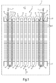
- Fig.1 shows a sectional top view onto a heat exchanger 1 or heat exchanger section according to a first embodiment.
- the heat exchanger 1 is of the finned tube type and may be used, for example, as part of a heat pump of a clothes dryer 2.
- the heat exchanger 1 comprises five pipes 3, 4 of basically the same 'U'-shape that have the same orientation and are aligned in the same direction. Although the pipes 3, 4 are shown in the same plane for the sake of simplicity, they are generally arranged in a three-dimensional structure.
- the pipes 3, 4 are mechanically and thermally connected to a connection structure formed by a stack of fins 5. At its frontal side A and its rearward side B, the stack of fins 5 is covered by a respective end plate 21 for mechanical protection.
- the straight legs of the pipes 3, 4 penetrate the fins 5 in a perpendicular fashion.
- the bends or bent sections 6 of the pipes 3, 4 are all situated on one side of the stack of fins 5 while the (open) ends 7 of the pipes 3, 4 are all situated on the other side of the stack of fins 5.
- the stack of fins 5 provides stiffness to the heat exchanger 1 and restricts relative movement of the pipes 3, 4.
- the stack of fins 5 restricts or dampens a propagation of externally induced forces and movements to elements of the heat exchanger1.
- the pipes 3, 4 are connected to form an open-ended fluid channel.
- the pipes 3, 4 are connected in pairs such that intermediate pipes 3 are connected to a respective pipe 3, 4 on both ends 7 and two terminal (or terminally located) pipes 4 are each connected to an intermediate pipe 3 on one end 7.
- the other end 7 of each terminal pipe 4 is not connected to a pipe 3, 4.
- a meander-like fluid channel 3 is formed that has two open ends 7 at the terminal pipes 4 which may be used as an inlet opening and outlet opening for the fluid F, respectively.
- connection between the pipes 3, 4 is effected using pipe elbows 8 that are bent 180° ('U'-shaped or 'C'-shaped pipe elbows 8).
- the pipe elbows 8 can be attached to the open ends 7 of the pipes 3, 4 by any suitable kind of connection, preferably by positive fitting for a particularly durable, compact and cost-effective connection.
- the positive fitting may comprise brazing, in particular flame brazing, of the pipes 3, 4 and pipe elbows 8.
- external fluid lines 9 may by fitted to the (yet) open ends 7 of the terminal pipes 4.
- fluid F may be introduced into and discharged from the fluid channel 3, 4, 8, as indicated by the straight arrows.
- the terminal pipes 4 are made of copper (or more generally of the same or a similar material as the external fluid lines 9), as indicated by the hatchings.
- the joints 10 between the terminal pipes 4 and the external fluid lines 9 do not show a material mismatch or a significant material mismatch anymore. It follows that these joints 10 are much more resistant against mechanical stresses than known from the prior art.
- the joints 10 and 11 are advantageously easily accessible from the outside.
- Fig.2 shows a sectional top view onto a heat exchanger 12a or heat exchanger section according to a second embodiment.
- the heat exchanger 12a has a generally similar form to the heat exchanger 1 and is also of the finned tube type and may be used, for example, as part of a heat pump of a clothes dryer 2.
- the heat exchanger 12a now only uses one intermediate pipe 13 that is shaped as a meander having multiple 'U' or 'C' shaped bent sections 6. There is thus no need anymore to connect the multiple intermediate pipes 3 of the heat exchanger 1.
- the only two remaining joints 14 are between the intermediate pipe 13 and the two terminal pipes 4, respectively.
- the terminal pipes 4 are of the same 'U' shape as used for the heat exchanger 1.
- the intermediate pipe 17 has been inserted into slits 18 within the stack of fins 19 for connection such that each 'U'-shaped section of the intermediate pipe 17 is inserted into a respective slit 18.
- the heat exchanger 12a may be manufactured by connecting the pipes 4, 13, followed by inserting the connected pipes 4, 13 into the connection structure (the stack of fins 19). To fastly hold the pipes within the stack of fins 19, the pipes 4, 13 may be expanded mechanically after having been inserted.
- Fig.3 shows a sectional top view onto a heat exchanger 12b or heat exchanger section according to a third embodiment.
- the terminal pipes 4 are formed as straight pipes 15 or tubes, connected at joints 16 to the intermediate pipe 17.
- the intermediate pipes 13 or 17 may have a straight end and may, for example, be connected to the terminal pipes 4 via a pipe elbow, e.g. a pipe elbow 8.
- Fig.4a shows a frontal view in direction A of fig.1 onto the heat exchanger 1 (now comprising six instead of three intermediate pipes 3).
- the frontally projecting 'U' shaped or 'C' shaped pipe elbows 8 are depicted as shown in fig.4b while the intermediate pipes 3 with their rearward projecting bent sections 6 are depicted as shown in fig.4c .
- the aluminium intermediate pipes 3 and pipe elbows 8 of fig.4b and fig.4c are depicted by open faces while the copper terminal pipes 4 are depicted by hatched faces, as e.g. seen in fig.4d .
- the heat exchanger 1 has a three-dimensional structure for good thermal exchange and for easy placement in the clothes dryer 2.
- the same basic structure may also apply to the heat exchangers 12a and 12b.
- Fig.5 shows a frontal view onto a heat exchanger 22according to a fourth embodiment.
- the heat exchanger 22 may be of a generally similar outline as the heat exchangers 1, 12a, or 12b.
- the elbows 8, 20 may now also comprise branched (three-point or three-ended) elbows 20 to allow for a parallel arrangement of the intermediate pipes 3.
- the number of the intermediate pipes may vary greatly and may comprise one or more than one, in particular five or more, intermediate pipes.
- the heat exchanger may also be a fluid/fluid heat exchanger.
- the heat exchanger may comprise two or more sets of pipes forming a respective fluid channel.
- any other suitable material e.g. steel.
- the pipes may be connected in series and/or in parallel.
- joints and pipes may be of a different form or position.
- the heat exchanger is not restricted to be a finned tube heat exchanger but may, for example, also be another type of tube heat exchanger.
- the heat exchanger may in particular be a part of a heat pump, but is not restricted to it.
- the heat exchanger may be a condenser of a condenser clothes dryer.
- the heat exchanger may in particular be a part of a household appliance, e.g. a clothes dryer or a refrigerator.
- the pipe elbows or branched bends may be of another form, e.g. crossed or four- or more-pointed.
Landscapes
- Engineering & Computer Science (AREA)
- Physics & Mathematics (AREA)
- Thermal Sciences (AREA)
- Mechanical Engineering (AREA)
- General Engineering & Computer Science (AREA)
- Heat-Exchange Devices With Radiators And Conduit Assemblies (AREA)
Priority Applications (3)
| Application Number | Priority Date | Filing Date | Title |
|---|---|---|---|
| EP10382222A EP2418448A1 (de) | 2010-08-09 | 2010-08-09 | Wärmetauscher, Haushaltsgerät, Verfahren zur Herstellung eines Wärmetauschers und Verfahren zur Installation eines Wärmetauschers |
| ES201031276A ES2399133B1 (es) | 2010-08-09 | 2010-08-23 | Intercambiador de calor, aparato domestico, metodo para fabricar un intercambiador de calor, y metodo para instalar un intercambiador de calor |
| PCT/IB2011/053547 WO2012020373A1 (en) | 2010-08-09 | 2011-08-09 | Heat exchanger, household appliance, method for manufacturing a heat exchanger, and method for installing a heat exchanger |
Applications Claiming Priority (1)
| Application Number | Priority Date | Filing Date | Title |
|---|---|---|---|
| EP10382222A EP2418448A1 (de) | 2010-08-09 | 2010-08-09 | Wärmetauscher, Haushaltsgerät, Verfahren zur Herstellung eines Wärmetauschers und Verfahren zur Installation eines Wärmetauschers |
Publications (1)
| Publication Number | Publication Date |
|---|---|
| EP2418448A1 true EP2418448A1 (de) | 2012-02-15 |
Family
ID=43253456
Family Applications (1)
| Application Number | Title | Priority Date | Filing Date |
|---|---|---|---|
| EP10382222A Withdrawn EP2418448A1 (de) | 2010-08-09 | 2010-08-09 | Wärmetauscher, Haushaltsgerät, Verfahren zur Herstellung eines Wärmetauschers und Verfahren zur Installation eines Wärmetauschers |
Country Status (2)
| Country | Link |
|---|---|
| EP (1) | EP2418448A1 (de) |
| ES (1) | ES2399133B1 (de) |
Cited By (3)
| Publication number | Priority date | Publication date | Assignee | Title |
|---|---|---|---|---|
| EP2871432A1 (de) * | 2013-11-06 | 2015-05-13 | BSH Hausgeräte GmbH | Wärmepumpe für ein Haushaltsgerät |
| WO2015068092A1 (en) | 2013-11-06 | 2015-05-14 | BSH Hausgeräte GmbH | Heat pump for a household appliance |
| CN107187862A (zh) * | 2017-06-20 | 2017-09-22 | 合肥太通制冷科技有限公司 | 一种铝管自动码垛生产线 |
Citations (4)
| Publication number | Priority date | Publication date | Assignee | Title |
|---|---|---|---|---|
| US1790241A (en) * | 1927-02-15 | 1931-01-27 | Murray Radiator Corp | Radiator |
| US3849854A (en) * | 1973-09-24 | 1974-11-26 | Emhart Corp | Method for making evaporator or condenser unit |
| US5644840A (en) * | 1992-06-17 | 1997-07-08 | Mitsubishi Denki Kabushiki Kaisha | Method of producing a plate-type heat exchanger |
| EP1550834A1 (de) * | 2004-01-02 | 2005-07-06 | Constantine Travassaros | Strahlplatte |
-
2010
- 2010-08-09 EP EP10382222A patent/EP2418448A1/de not_active Withdrawn
- 2010-08-23 ES ES201031276A patent/ES2399133B1/es not_active Withdrawn - After Issue
Patent Citations (4)
| Publication number | Priority date | Publication date | Assignee | Title |
|---|---|---|---|---|
| US1790241A (en) * | 1927-02-15 | 1931-01-27 | Murray Radiator Corp | Radiator |
| US3849854A (en) * | 1973-09-24 | 1974-11-26 | Emhart Corp | Method for making evaporator or condenser unit |
| US5644840A (en) * | 1992-06-17 | 1997-07-08 | Mitsubishi Denki Kabushiki Kaisha | Method of producing a plate-type heat exchanger |
| EP1550834A1 (de) * | 2004-01-02 | 2005-07-06 | Constantine Travassaros | Strahlplatte |
Cited By (4)
| Publication number | Priority date | Publication date | Assignee | Title |
|---|---|---|---|---|
| EP2871432A1 (de) * | 2013-11-06 | 2015-05-13 | BSH Hausgeräte GmbH | Wärmepumpe für ein Haushaltsgerät |
| WO2015068092A1 (en) | 2013-11-06 | 2015-05-14 | BSH Hausgeräte GmbH | Heat pump for a household appliance |
| CN105705899A (zh) * | 2013-11-06 | 2016-06-22 | Bsh家用电器有限公司 | 用于家用器具的热泵 |
| CN107187862A (zh) * | 2017-06-20 | 2017-09-22 | 合肥太通制冷科技有限公司 | 一种铝管自动码垛生产线 |
Also Published As
| Publication number | Publication date |
|---|---|
| ES2399133B1 (es) | 2014-06-09 |
| ES2399133R1 (es) | 2013-08-08 |
| ES2399133A2 (es) | 2013-03-26 |
Similar Documents
| Publication | Publication Date | Title |
|---|---|---|
| EP2831528A1 (de) | Wärmetauscher, haushaltsanwendung mit solch einem wärmetauscher und verfahren zur herstellung solch eines wärmetauschers | |
| JP5944009B2 (ja) | 二重管式熱交換器および冷凍サイクル装置 | |
| KR20070065887A (ko) | 열 교환기 | |
| EP4332489B1 (de) | Rohrverbindungsstruktur und kältekreislaufvorrichtung | |
| EP2639539A1 (de) | Röhre für einen wärmetauscher | |
| JP2017075741A (ja) | 熱交換器 | |
| EP2645042A1 (de) | Wärmetauscher, Haushaltsgerät mit solch einem Wärmetauscher und Verfahren zur Herstellung solch eines Wärmetauschers | |
| JP2009103393A (ja) | 熱交換器 | |
| EP2418448A1 (de) | Wärmetauscher, Haushaltsgerät, Verfahren zur Herstellung eines Wärmetauschers und Verfahren zur Installation eines Wärmetauschers | |
| WO2012020373A1 (en) | Heat exchanger, household appliance, method for manufacturing a heat exchanger, and method for installing a heat exchanger | |
| EP2735835A2 (de) | Interner Wärmetauscher für eine Klimaanlage | |
| WO2009110664A1 (en) | Heat exchanger | |
| WO2013118527A1 (ja) | 熱交換器 | |
| KR101422074B1 (ko) | 열교환용 인아웃렛 파이프의 고정구조 | |
| JP3845565B2 (ja) | 熱交換器 | |
| JP2006322636A (ja) | 熱交換器 | |
| JP2011099620A (ja) | 熱交換器 | |
| WO2012142071A1 (en) | Heat exchanger | |
| JPH11183075A5 (de) | ||
| JP3438341B2 (ja) | 熱交換器 | |
| JP2017133814A (ja) | 熱交換器 | |
| JP4615422B2 (ja) | 伝熱管、給湯用熱交換器およびヒートポンプ給湯器 | |
| KR100803774B1 (ko) | 공기조화기의 설치배관 | |
| JP2001041680A (ja) | 多管式のegrガス冷却装置およびその製造方法 | |
| CN213901570U (zh) | 螺旋状卷曲的盘管式冷凝器及冰箱 |
Legal Events
| Date | Code | Title | Description |
|---|---|---|---|
| AK | Designated contracting states |
Kind code of ref document: A1 Designated state(s): AL AT BE BG CH CY CZ DE DK EE ES FI FR GB GR HR HU IE IS IT LI LT LU LV MC MK MT NL NO PL PT RO SE SI SK SM TR |
|
| AX | Request for extension of the european patent |
Extension state: BA ME RS |
|
| PUAI | Public reference made under article 153(3) epc to a published international application that has entered the european phase |
Free format text: ORIGINAL CODE: 0009012 |
|
| STAA | Information on the status of an ep patent application or granted ep patent |
Free format text: STATUS: THE APPLICATION IS DEEMED TO BE WITHDRAWN |
|
| 18D | Application deemed to be withdrawn |
Effective date: 20120817 |