EP2419630B1 - Éolienne et dispositif d'entraînement pour le réglage d'une pale de rotor - Google Patents
Éolienne et dispositif d'entraînement pour le réglage d'une pale de rotor Download PDFInfo
- Publication number
- EP2419630B1 EP2419630B1 EP10711174.2A EP10711174A EP2419630B1 EP 2419630 B1 EP2419630 B1 EP 2419630B1 EP 10711174 A EP10711174 A EP 10711174A EP 2419630 B1 EP2419630 B1 EP 2419630B1
- Authority
- EP
- European Patent Office
- Prior art keywords
- rotor
- wind energy
- synchronous motor
- energy plant
- rotor blade
- Prior art date
- Legal status (The legal status is an assumption and is not a legal conclusion. Google has not performed a legal analysis and makes no representation as to the accuracy of the status listed.)
- Not-in-force
Links
Images


Classifications
-
- F—MECHANICAL ENGINEERING; LIGHTING; HEATING; WEAPONS; BLASTING
- F03—MACHINES OR ENGINES FOR LIQUIDS; WIND, SPRING, OR WEIGHT MOTORS; PRODUCING MECHANICAL POWER OR A REACTIVE PROPULSIVE THRUST, NOT OTHERWISE PROVIDED FOR
- F03D—WIND MOTORS
- F03D9/00—Adaptations of wind motors for special use; Combinations of wind motors with apparatus driven thereby; Wind motors specially adapted for installation in particular locations
- F03D9/20—Wind motors characterised by the driven apparatus
- F03D9/25—Wind motors characterised by the driven apparatus the apparatus being an electrical generator
-
- F—MECHANICAL ENGINEERING; LIGHTING; HEATING; WEAPONS; BLASTING
- F03—MACHINES OR ENGINES FOR LIQUIDS; WIND, SPRING, OR WEIGHT MOTORS; PRODUCING MECHANICAL POWER OR A REACTIVE PROPULSIVE THRUST, NOT OTHERWISE PROVIDED FOR
- F03D—WIND MOTORS
- F03D15/00—Transmission of mechanical power
- F03D15/20—Gearless transmission, i.e. direct-drive
-
- F—MECHANICAL ENGINEERING; LIGHTING; HEATING; WEAPONS; BLASTING
- F03—MACHINES OR ENGINES FOR LIQUIDS; WIND, SPRING, OR WEIGHT MOTORS; PRODUCING MECHANICAL POWER OR A REACTIVE PROPULSIVE THRUST, NOT OTHERWISE PROVIDED FOR
- F03D—WIND MOTORS
- F03D7/00—Controlling wind motors
- F03D7/02—Controlling wind motors the wind motors having rotation axis substantially parallel to the air flow entering the rotor
- F03D7/022—Adjusting aerodynamic properties of the blades
- F03D7/0224—Adjusting blade pitch
-
- F—MECHANICAL ENGINEERING; LIGHTING; HEATING; WEAPONS; BLASTING
- F03—MACHINES OR ENGINES FOR LIQUIDS; WIND, SPRING, OR WEIGHT MOTORS; PRODUCING MECHANICAL POWER OR A REACTIVE PROPULSIVE THRUST, NOT OTHERWISE PROVIDED FOR
- F03D—WIND MOTORS
- F03D80/00—Details, components or accessories not provided for in groups F03D1/00 - F03D17/00
- F03D80/70—Bearing or lubricating arrangements
-
- F—MECHANICAL ENGINEERING; LIGHTING; HEATING; WEAPONS; BLASTING
- F05—INDEXING SCHEMES RELATING TO ENGINES OR PUMPS IN VARIOUS SUBCLASSES OF CLASSES F01-F04
- F05B—INDEXING SCHEME RELATING TO WIND, SPRING, WEIGHT, INERTIA OR LIKE MOTORS, TO MACHINES OR ENGINES FOR LIQUIDS COVERED BY SUBCLASSES F03B, F03D AND F03G
- F05B2210/00—Working fluid
- F05B2210/10—Kind or type
- F05B2210/12—Kind or type gaseous, i.e. compressible
-
- F—MECHANICAL ENGINEERING; LIGHTING; HEATING; WEAPONS; BLASTING
- F05—INDEXING SCHEMES RELATING TO ENGINES OR PUMPS IN VARIOUS SUBCLASSES OF CLASSES F01-F04
- F05B—INDEXING SCHEME RELATING TO WIND, SPRING, WEIGHT, INERTIA OR LIKE MOTORS, TO MACHINES OR ENGINES FOR LIQUIDS COVERED BY SUBCLASSES F03B, F03D AND F03G
- F05B2220/00—Application
- F05B2220/70—Application in combination with
- F05B2220/706—Application in combination with an electrical generator
- F05B2220/7064—Application in combination with an electrical generator of the alternating current (A.C.) type
- F05B2220/70642—Application in combination with an electrical generator of the alternating current (A.C.) type of the synchronous type
-
- F—MECHANICAL ENGINEERING; LIGHTING; HEATING; WEAPONS; BLASTING
- F05—INDEXING SCHEMES RELATING TO ENGINES OR PUMPS IN VARIOUS SUBCLASSES OF CLASSES F01-F04
- F05B—INDEXING SCHEME RELATING TO WIND, SPRING, WEIGHT, INERTIA OR LIKE MOTORS, TO MACHINES OR ENGINES FOR LIQUIDS COVERED BY SUBCLASSES F03B, F03D AND F03G
- F05B2260/00—Function
- F05B2260/70—Adjusting of angle of incidence or attack of rotating blades
-
- Y—GENERAL TAGGING OF NEW TECHNOLOGICAL DEVELOPMENTS; GENERAL TAGGING OF CROSS-SECTIONAL TECHNOLOGIES SPANNING OVER SEVERAL SECTIONS OF THE IPC; TECHNICAL SUBJECTS COVERED BY FORMER USPC CROSS-REFERENCE ART COLLECTIONS [XRACs] AND DIGESTS
- Y02—TECHNOLOGIES OR APPLICATIONS FOR MITIGATION OR ADAPTATION AGAINST CLIMATE CHANGE
- Y02E—REDUCTION OF GREENHOUSE GAS [GHG] EMISSIONS, RELATED TO ENERGY GENERATION, TRANSMISSION OR DISTRIBUTION
- Y02E10/00—Energy generation through renewable energy sources
- Y02E10/70—Wind energy
- Y02E10/72—Wind turbines with rotation axis in wind direction
Definitions
- Wind turbines are used to convert kinetic energy of wind by means of a rotor into electrical energy, for example, to feed them into an electrical energy transmission network.
- the kinetic energy of a wind flow acts on rotor blades, which are mounted on a rotor hub and are set in a rotational movement in a wind flow.
- the rotary motion is transmitted directly or by means of a gearbox to a generator, which converts the kinetic energy into electrical energy.
- a generator comprising the drive train is arranged in conventional wind turbines in a mounted on a tower nacelle.
- Rotor blades of wind turbines have an aerodynamic profile, which causes a pressure difference, which is due to a flow velocity difference between the suction and pressure side of a rotor blade. This pressure difference results in a torque acting on the rotor, which influences its speed.
- Wind turbines mainly have a horizontal axis of rotation.
- a wind direction tracking of the nacelle usually takes place by means of servomotors.
- the gondola connected to the tower via an azimuth bearing is rotated about its axis.
- Rotors with 3 rotor blades have prevailed over single, double or four-blade rotors, since three-blade rotors are easier to control in terms of vibration technology.
- tipping forces acting on a rotor blade due to wind shadow effects are amplified by an opposing rotor blade offset by 180 °, resulting in increased demands on mechanics and material.
- Rotors with 5 or 7 rotor blades lead to aerodynamic states that are mathematically relatively complicated describable, since air flows on the rotor blades influence each other.
- such rotors do not allow increases in yield, which are in an economic relationship to the additional expense compared with rotors with 3 rotor blades.
- wind turbines have pitch drive systems for rotor blade adjustment.
- pitch of rotor blades By adjusting the pitch of rotor blades, the flow rate differences between the suction and pressure sides of the rotor blades are changed. This in turn affects the torque acting on the rotor and the rotor speed.
- a rotor blade adjustment takes place via a hydraulically actuated cylinder or via an electric or geared motor.
- a power-driven adjustment meshes with an output gear with a ring gear, which surrounds a rotor blade and is connected to this in the region of a bearing ring.
- a pitch drive system which has a gearless direct drive, the rotor and stator are arranged concentrically with each other in a plane.
- this pitch drive system has the disadvantage that rotor and stator must be adapted in terms of their dimensions to the respective rotor blade. This limits a usability of the WO 2005/019642 A1 known pitch drive system for different rotor blade sizes considerably.
- a wind energy plant with a rotor wherein the rotor comprises a mounted on a nacelle rotor hub and a plurality of rotor blades and with the rotor, an electric generator is connected.
- the rotor blades are each provided with an electric drive device for adjusting a rotor blade.
- a wind energy plant with a rotor wherein the rotor comprises a mounted on a nacelle rotor hub and a plurality of rotor blades and with the rotor, an electric generator is connected.
- the rotor blades can be adjustable.
- the generator is directly driven by the rotor.
- a wind energy plant with a rotor wherein the rotor comprises a mounted on a nacelle rotor hub and a plurality of rotor blades and with the rotor, an electric generator is connected.
- WO 2007/098759 A2 From the WO 2007/098759 A2 is a wind turbine with a rotor mounted on a nacelle known, with the rotor, a generator is connected.
- the rotor comprises a rotor hub and a plurality of rotor blades, which are adjustable by means of a respective drive device.
- the respective drive device is arranged concentrically to a rotor blade bearing of the respective rotor blade on the rotor hub and comprises a permanently excited synchronous motor.
- the stator of the respective synchronous motor comprises a respective bobbin mounted on the rotor hub.
- the rotor of the respective synchronous motor is arranged to form a radially extending air gap at a radial distance from the stator of the respective synchronous motor.
- the rotor acts on a sun gear of a planetary gear. It has a permanent magnet arrangement.
- the synchronous motor is in the WO 2007/098759 A2 referred to as direct electrical drive
- the present invention has for its object to provide a wind turbine, the pitch drive system can be used for different rotor blade sizes and allows fast, accurate rotor blade adjustment, as well as specify suitable system components.
- the wind power plant according to the invention has a rotor which comprises a rotor hub mounted on a nacelle and a plurality of rotor blades.
- An electric generator is connected to the rotor.
- each designed as a direct drive electric drive means for adjusting a rotor blade is provided, which is arranged concentrically to a rotor blade bearing on the rotor hub and comprises a permanently excited synchronous motor.
- a stator of the synchronous motor comprises a bobbin mounted on the rotor hub.
- a rotor of the synchronous motor is arranged to form an axially extending air gap at an axial distance from the stator.
- the rotor has a permanent magnet arrangement on a carrier plate which is connected to a rotor blade shaft.
- a wear-free, accurate and dynamic single-blade adjustment is achieved according to the invention compared to conventional pitch drive systems.
- An embodiment of the synchronous motor in a layered design allows its use for a variety of rotor blade sizes and easy installation, since the rotor and stator can be handled separately.
- a further simplification of the assembly can be achieved if both rotor and stator are each divided into circular segment-shaped modules, which together form the rotor or stator.
- the rotor and stator of the synchronous motor are arranged in separate planes and surround the rotor blade bearing.
- the synchronous motor For example, be designed as a segment motor, and the permanent magnet assembly may include segmentally arranged on the support plate permanent magnets, which cooperate with segmented coils of the bobbin. This allows a cost-effective production of a pitch drive system by resorting to a variety of similar components.
- a rotor blade according to a further advantageous embodiment of the present invention by means of a wedge mechanism can be locked, which comprises an actuatable by means of a first and second wedge body grater body.
- the first and the second wedge body in each case have mutually interacting contact surfaces.
- a connected to the rotor blade and rotatable about this with its axis locking member is provided.
- the friction body exerts a contact force on the locking element during a relative movement between the first and second wedge bodies.
- a rotor blade can be easily and safely locked in its adjustment.
- a rotor blade can be fixed in a safe 90 ° position by means of a conical, electromagnetically unlockable index pin.
- wind turbine has a rotor 1, which includes a mounted on a nacelle 2 rotor hub 11 and a plurality of rotor blades 12, which are each adjustable by means of a separate pitch system 13.
- a rotor 32 of an electric generator 3 is rotatable with the rotor hub 11 and integrated therein.
- a rotor bearing 14 connects to a stator 31 of the generator 3.
- FIG. 1 illustrated wind turbine, an energy transfer device 4, which comprises a concentric with the rotor bearing 14 arranged rotary transformer for powering the arranged in the rotor hub 11 pitch system 13.
- An annular primary part 41 of the rotary transformer is connected to the nacelle 2 via the rotor bearing 14.
- the primary part 41 and the rotor bearing 14 can be combined to form an integrated system component.
- the rotary transformer comprises a connected to the rotor hub 11 and rotatable with this annular secondary part 42.
- the secondary part 42 is adjacent to a rotor winding of the generator 3 and arranged concentrically to this.
- a first frequency converter 43 is provided, which is connected between the primary part 41 and an in FIG. 1 not explicitly shown supply voltage source is connected.
- the energy transmission device 4 further comprises a second frequency converter 44 for generating a low-frequency load voltage a high-frequency transformed excitation voltage.
- the second frequency converter 44 is connected between the secondary part 42 and the pitch system 13.
- a rectifier for generating a DC voltage from a high-frequency transformed exciter voltage may be provided, which is connected between the secondary part 42 and the electrical loads in the rotor hub 11.
- the rotary transformer may be part of a rotor 1 connected to the generator 3 transmission and provide a high-frequency AC voltage via an electrical connector at a rotor-side gear shaft end.
- the primary part 41 and the secondary part 42 of the rotary transformer of in FIG. 1 shown wind turbine are arranged axially spaced in separate planes and have substantially the same diameter.
- An air gap of the rotary transformer in which a high-frequency electromagnetic field is generated by the exciter voltage, extends axially between the primary part 41 and the secondary part 42.
- primary part 41 and secondary part 42 could also be arranged concentrically in one another in a common plane, and the air gap of the rotary transformer could extending radially between the primary part 41 and secondary part 42.
- Control and status signals can also be transmitted from and to the pitch system 13 via the rotary transformer.
- the control and status signals may also be transmitted via a WLAN connection or a suitable other radio connection.
- a permanently excited synchronous motor 131 is provided, which is arranged concentrically to a rotor blade bearing 121 on the rotor hub 11.
- a stator 132 of the synchronous motor 131 comprises a bobbin mountable on a ring 111 of the rotor hub 11.
- a rotor 133 of the synchronous motor 131 is disposed at an axial distance from the stator 132 to form an axially extending air gap and has a permanent magnet arrangement on a carrier ring 123 which is connected to a rotor blade shaft 122.
- Rotor 133 and stator 132 of the synchronous motor 131 are arranged in separate planes and surround the rotor blade bearing 121.
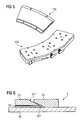
- the synchronous motor 131 is formed as a segment motor (see also FIG. 5 ).
- the permanent magnet arrangement comprises segment-wise on the carrier ring 123 around the rotor blade bearing 121 arranged permanent magnets 135 which cooperate with segmented coils 134 of the bobbin.
- the locking device 5 comprises a friction body 53 which can be actuated by means of a first wedge body 51 and a second wedge body 52.
- the first wedge body 51 and the second wedge body 52 each have mutually interacting contact surfaces 511, 521.
- the locking device 5 comprises a connected to the rotor blade 12 and rotatable about this axis about its locking member 54, which may for example be integrally formed on the support ring 123 or in this.
- the friction body 53 exerts a contact pressure on the locking element 54 when the two wedge bodies are moved toward one another or when a wedge body is displaced in the direction of the other wedge body and the other wedge body is fixed.
Landscapes
- Engineering & Computer Science (AREA)
- Mechanical Engineering (AREA)
- Sustainable Development (AREA)
- Sustainable Energy (AREA)
- Chemical & Material Sciences (AREA)
- Combustion & Propulsion (AREA)
- Life Sciences & Earth Sciences (AREA)
- General Engineering & Computer Science (AREA)
- Power Engineering (AREA)
- Physics & Mathematics (AREA)
- Fluid Mechanics (AREA)
- Wind Motors (AREA)
- Connection Of Motors, Electrical Generators, Mechanical Devices, And The Like (AREA)
Claims (11)
- Rotor d'une éolienne,- le rotor comprenant un moyeu de rotor (11) et une pluralité de pales de rotor (12),- les pales de rotor (12) étant réglables au moyen d'un dispositif d'entraînement respectif (13),- le dispositif d'entraînement respectif (13) étant disposé sur le moyeu de rotor (11), concentriquement par rapport à un palier de pale de rotor (121) de la pale de rotor respective (12) et comprenant un moteur synchrone (131) suscité en permanence.- le stator (132) du moteur synchrone respectif (131) comprenant un corps de bobine respectif monté sur le moyeu de rotor (11),- le rotor (133) du moteur synchrone respectif (131) étant disposé avec un écart axial par rapport au stator (132) du moteur synchrone respectif (131) pour former un espace d'air s'étendant axialement,- le rotor (133) du moteur synchrone respectif (131) présentant un agencement respectif d'aimants permanents sur une plaque de support respective (123) qui est reliée à une tige respective (122) de pale de rotor,- le dispositif d'entraînement respectif (13) étant réalisé comme entraînement électrique direct.
- Rotor selon la revendication 1, dans lequel
le rotor (133) et le stator (132) du moteur synchrone respectif (131) sont disposés dans des plans séparés et entourent le palier respectif (121) de pale de rotor. - Rotor selon l'une quelconque des revendications 1 ou 2, dans lequel- le moteur synchrone respectif (131) est réalisé comme moteur à segment et- l'agencement respectif à aimants permanents comprend des aimants permanents (135) disposés par segments sur la plaque de support respective (123), lesquels coopèrent avec des bobines respectives (134) du corps de bobine respectif, disposées par segments.
- Rotor selon l'une quelconque des revendications 1, 2 ou 3, dans lequel- une pale de rotor (12) est blocable au moyen d'un mécanisme à clavette pour maintenir son réglage, lequel mécanisme à clavette comprend un corps de frottement (53) actionnable au moyen d'un premier et d'un deuxième corps de clavette (51, 52),- le premier et le deuxième corps de clavette (51, 52) présentent des surfaces d'appui (511, 521) agissant alternativement l'une avec l'autre,- un élément de blocage relié à la pale de rotor (12) et rotatif avec celle-ci autour de son axe est ménagé, et- le corps de frottement (53) exerce une force de pression sur l'élément de blocage lors d'un mouvement relatif entre le premier et le deuxième corps de clavette (51, 52).
- Éolienne munie d'un rotor (1) logé sur un fuseau, selon l'une quelconque des revendications 1 à 4, et munie d'un générateur électrique (3) relié au rotor (1).
- Éolienne selon la revendication 5, dans laquelle- un transmetteur rotatif disposé concentriquement par rapport à un palier de rotor (14) est ménagé pour l'alimentation en énergie des dispositifs d'entraînement (13),- le transmetteur rotatif comprend une partie primaire (41) reliée au fuseau et une partie secondaire (42) se trouvant dans le moyeu de rotor (11) et rotative avec celle-ci,- un premier convertisseur de fréquence (43) est ménagé pour générer une tension d'excitation à haute fréquence à partir d'une tension d'alimentation à basse fréquence, lequel est raccordé entre la partie primaire (41) et une source de tension d'alimentation, et- un deuxième convertisseur de fréquence (44) est ménagé pour générer une tension d'appareil à basse fréquence à partir d'une tension d'excitation transformée à haute fréquence, lequel est raccordé entre la partie secondaire (42) et les appareils électriques dans le moyeu de rotor (11).
- Éolienne selon la revendication 6, dans laquelle un enroulement rotorique se raccorde à la partie secondaire (42) du transmetteur rotatif.
- Éolienne selon la revendication 6 ou 7, dans laquelle la partie primaire (41) et la partie secondaire (42) sont disposées concentriquement l'une dans l'autre dans un plan commun, et dans laquelle un espace d'air du transmetteur rotatif s'étend radialement entre la partie primaire (41) et la partie secondaire (42).
- Éolienne selon la revendication 6 ou 7, dans laquelle
la partie primaire (41) et la partie secondaire (42) sont disposées de manière axialement décalée dans des plans séparés et dans laquelle un espace d'air du transmetteur rotatif s'étend axialement entre la partie primaire (41) et la partie secondaire (42). - Éolienne selon l'une quelconque des revendications 6 à 9, dans laquelle le transmetteur rotatif est intégré dans le palier de rotor (14).
- Éolienne selon l'une quelconque des revendications 4 à 10, dans laquelle un induit (32) du générateur (3) est rotatif avec le moyeu de rotor (11).
Applications Claiming Priority (2)
| Application Number | Priority Date | Filing Date | Title |
|---|---|---|---|
| DE102009017028.6A DE102009017028B4 (de) | 2009-04-14 | 2009-04-14 | Windenergieanlage und Antriebseinrichtung zur Verstellung eines Rotorblatts |
| PCT/EP2010/052810 WO2010118918A2 (fr) | 2009-04-14 | 2010-03-05 | Éolienne et dispositif d'entraînement pour le réglage d'une pale de rotor |
Publications (2)
| Publication Number | Publication Date |
|---|---|
| EP2419630A2 EP2419630A2 (fr) | 2012-02-22 |
| EP2419630B1 true EP2419630B1 (fr) | 2014-11-19 |
Family
ID=42932245
Family Applications (1)
| Application Number | Title | Priority Date | Filing Date |
|---|---|---|---|
| EP10711174.2A Not-in-force EP2419630B1 (fr) | 2009-04-14 | 2010-03-05 | Éolienne et dispositif d'entraînement pour le réglage d'une pale de rotor |
Country Status (6)
| Country | Link |
|---|---|
| US (1) | US20120098263A1 (fr) |
| EP (1) | EP2419630B1 (fr) |
| CN (2) | CN102395781B (fr) |
| CA (1) | CA2758469A1 (fr) |
| DE (1) | DE102009017028B4 (fr) |
| WO (1) | WO2010118918A2 (fr) |
Families Citing this family (17)
| Publication number | Priority date | Publication date | Assignee | Title |
|---|---|---|---|---|
| DE102009017028B4 (de) * | 2009-04-14 | 2014-08-21 | Siemens Aktiengesellschaft | Windenergieanlage und Antriebseinrichtung zur Verstellung eines Rotorblatts |
| DE102011082811A1 (de) * | 2011-09-16 | 2013-03-21 | Aktiebolaget Skf | Lager und Windkraftanlage |
| DE102011082810A1 (de) * | 2011-09-16 | 2013-03-21 | Aktiebolaget Skf | Lager und Windkraftanlage |
| DE102011084580A1 (de) * | 2011-10-14 | 2013-04-18 | Universität Bremen | Windkraftmaschine |
| EP2594787A1 (fr) * | 2011-11-17 | 2013-05-22 | Alstom Wind, S.L.U. | Éolienne |
| ITTO20111113A1 (it) * | 2011-12-05 | 2013-06-06 | Wilic Sarl | Impianto eolico per la generazione di energia elettrica |
| DE102012202029A1 (de) * | 2012-02-10 | 2013-08-14 | Aktiebolaget Skf | Lager und Windkraftanlage |
| EP2713046B1 (fr) * | 2012-09-26 | 2018-08-01 | Siemens Aktiengesellschaft | Eolienne |
| CN103291552B (zh) * | 2013-06-17 | 2015-04-22 | 浙江大学宁波理工学院 | 多片多驱动桨叶风力机结构 |
| CN103726996B (zh) * | 2014-01-14 | 2017-06-27 | 北京金风科创风电设备有限公司 | 叶片变桨限位结构以及风力发电机 |
| DE102014203508B9 (de) | 2014-02-26 | 2018-07-19 | youWINenergy GmbH | Rotorblattlageranordnung für eine Windenergieanlage |
| EP3280038A1 (fr) | 2016-08-03 | 2018-02-07 | Siemens Aktiengesellschaft | Dispositif d'entrainement |
| CN112228279B (zh) * | 2019-06-30 | 2023-03-03 | 北京金风科创风电设备有限公司 | 发电机及风力发电机组 |
| CN110994896A (zh) * | 2019-12-20 | 2020-04-10 | 上海致远绿色能源股份有限公司 | 一种风力发电机变桨系统用的供电装置 |
| CN111963392B (zh) * | 2020-07-22 | 2021-12-10 | 明阳智慧能源集团股份公司 | 一种解决风力发电机组变桨轴承零位齿磨损的方法 |
| CN113819089B (zh) * | 2021-09-27 | 2022-09-27 | 合肥恒大江海泵业股份有限公司 | 一体式潜水电泵叶片调节装置 |
| CN117072374A (zh) * | 2023-09-28 | 2023-11-17 | 杭州富疆科技有限公司 | 一种风力发电机组变桨系统 |
Citations (3)
| Publication number | Priority date | Publication date | Assignee | Title |
|---|---|---|---|---|
| WO2001006623A1 (fr) * | 1999-04-23 | 2001-01-25 | Aerpac Holding B.V. | Generateur |
| US20040041409A1 (en) * | 2002-08-30 | 2004-03-04 | Gabrys Christopher W. | Wind turbine |
| WO2007098759A2 (fr) * | 2006-02-28 | 2007-09-07 | Vestas Wind Systems A/S | Rotor d'éolienne, mécanisme de commande de rotation et procédé de commande d'au moins une pale d'un rotor d'éolienne |
Family Cites Families (16)
| Publication number | Priority date | Publication date | Assignee | Title |
|---|---|---|---|---|
| US6600240B2 (en) * | 1997-08-08 | 2003-07-29 | General Electric Company | Variable speed wind turbine generator |
| ATE463877T1 (de) | 2000-05-19 | 2010-04-15 | Portescap Singapore Pte Ltd | Scheibenförmiger schrittmotor |
| WO2005019642A1 (fr) | 2003-08-21 | 2005-03-03 | General Electric Company | Changement de pas des pales d'une eolienne a l'aide d'un moteur pas a pas electrique |
| DE102005016156A1 (de) | 2005-01-11 | 2006-10-12 | Klinger, Friedrich, Prof. Dr. Ing. | Windenergieanlage |
| JPWO2006126298A1 (ja) * | 2005-05-23 | 2008-12-25 | 大西 一正 | 円盤状の切断ブレードを備えた切断装置 |
| DE102005034899A1 (de) * | 2005-07-26 | 2007-02-01 | Repower Systems Ag | Windenergieanlage mit Einzelpitcheinrichtungen |
| DE102006009127A1 (de) * | 2006-02-24 | 2007-09-06 | Repower Systems Ag | Energieversorgung für Blattverstelleinrichtung einer Windenergieanlage |
| US7218012B1 (en) * | 2006-05-31 | 2007-05-15 | General Electric Company | Emergency pitch drive power supply |
| DE102007013421A1 (de) * | 2007-03-20 | 2008-09-25 | Siemens Ag | Bremseinrichtung mit einem Keilmechanismus |
| US7709972B2 (en) * | 2007-08-30 | 2010-05-04 | Mitsubishi Heavy Industries, Ltd. | Wind turbine system for satisfying low-voltage ride through requirement |
| TWI381613B (zh) * | 2008-12-02 | 2013-01-01 | Sunonwealth Electr Mach Ind Co | 馬達轉子 |
| US20100180720A1 (en) * | 2009-01-19 | 2010-07-22 | Gm Global Technology Operations, Inc. | Motor module for attachment to a transmission housing of a modular transmission assembly |
| DE102009017028B4 (de) * | 2009-04-14 | 2014-08-21 | Siemens Aktiengesellschaft | Windenergieanlage und Antriebseinrichtung zur Verstellung eines Rotorblatts |
| US20110254281A1 (en) | 2009-06-16 | 2011-10-20 | Mitsubishi Heavy Industries, Ltd. | Wind turbine generator |
| WO2011004248A1 (fr) | 2009-07-09 | 2011-01-13 | Clipper Windpower, Inc. | Système dorientation motorisé déolienne |
| JP4819939B2 (ja) | 2009-11-04 | 2011-11-24 | Thk株式会社 | ロータリーモータアクチュエータ及び水平軸風車 |
-
2009
- 2009-04-14 DE DE102009017028.6A patent/DE102009017028B4/de not_active Expired - Fee Related
-
2010
- 2010-03-05 EP EP10711174.2A patent/EP2419630B1/fr not_active Not-in-force
- 2010-03-05 CN CN201080016946.7A patent/CN102395781B/zh not_active Expired - Fee Related
- 2010-03-05 WO PCT/EP2010/052810 patent/WO2010118918A2/fr not_active Ceased
- 2010-03-05 US US13/264,557 patent/US20120098263A1/en not_active Abandoned
- 2010-03-05 CA CA2758469A patent/CA2758469A1/fr not_active Abandoned
- 2010-04-14 CN CN2010201779852U patent/CN201794712U/zh not_active Expired - Lifetime
Patent Citations (3)
| Publication number | Priority date | Publication date | Assignee | Title |
|---|---|---|---|---|
| WO2001006623A1 (fr) * | 1999-04-23 | 2001-01-25 | Aerpac Holding B.V. | Generateur |
| US20040041409A1 (en) * | 2002-08-30 | 2004-03-04 | Gabrys Christopher W. | Wind turbine |
| WO2007098759A2 (fr) * | 2006-02-28 | 2007-09-07 | Vestas Wind Systems A/S | Rotor d'éolienne, mécanisme de commande de rotation et procédé de commande d'au moins une pale d'un rotor d'éolienne |
Also Published As
| Publication number | Publication date |
|---|---|
| CN102395781B (zh) | 2014-07-09 |
| WO2010118918A2 (fr) | 2010-10-21 |
| CA2758469A1 (fr) | 2010-10-21 |
| DE102009017028A1 (de) | 2010-11-11 |
| WO2010118918A3 (fr) | 2010-12-23 |
| CN201794712U (zh) | 2011-04-13 |
| DE102009017028B4 (de) | 2014-08-21 |
| EP2419630A2 (fr) | 2012-02-22 |
| CN102395781A (zh) | 2012-03-28 |
| US20120098263A1 (en) | 2012-04-26 |
Similar Documents
| Publication | Publication Date | Title |
|---|---|---|
| EP2419630B1 (fr) | Éolienne et dispositif d'entraînement pour le réglage d'une pale de rotor | |
| EP2467600B1 (fr) | Éolienne et procédé de commande du fonctionnement d'une éolienne | |
| DE69830264T2 (de) | Langsamlaufende getriebelose Windturbine | |
| EP2419629B1 (fr) | Éolienne et dispositif de transfert d'énergie pour éolienne | |
| DE2460413A1 (de) | Elektrogenerator-anordnung | |
| EP2379879B1 (fr) | Ensemble génératrice pour éolienne | |
| DE3903399A1 (de) | Windkraftanlage | |
| DE102009018361B4 (de) | Anordnung zur Pitchwinkel-Verstellung mindestens eines Rotorblatts und Maschine, insbesondere Windkraftanlage | |
| EP2379882B1 (fr) | Installation exploitant une force de flux | |
| DE102010020426A1 (de) | Elektrische Maschine, insbesondere für eine Windkraftanlage | |
| EP4008898A1 (fr) | Agencement d'engrenage et de générateur d'une éolienne comprenant un frein | |
| EP3507485A1 (fr) | Moyeu pour pale d'hélice d'une éolienne, et éolienne doté de ce moyeu | |
| WO2010121586A2 (fr) | Chaîne cinématique pour éolienne, nacelle d'éolienne, éolienne et parc d'éoliennes ainsi que conteneur standard | |
| WO2019030300A1 (fr) | Générateur pour une éolienne et éolienne comprenant celui-ci | |
| EP3510281B1 (fr) | Dispositif d'arrêt de rotor pour une éolienne et procédé | |
| EP3807517B1 (fr) | Turbine | |
| EP3047141B1 (fr) | Pale de rotor pour éolienne, moyen de rotor, chaîne cinématique, nacelle, éolienne et parc d'éoliennes | |
| DE202012012783U1 (de) | Vorrichtung und System zum Umwandeln kinetischer Energie eines Abluftstromes in elektrische Energie | |
| DE102011008061A1 (de) | Drehzahlstabilisierung einer Windkraftanlage | |
| EP3404256A1 (fr) | Dispositif d'ajustement des pales de rotor d'une installation génératrice d'énergie à flux | |
| DE20306166U1 (de) | Windkraftanlage mit gegenläufigen Rotoren | |
| WO2013034237A2 (fr) | Moteur asynchrone à alimentation double | |
| DE10027107A1 (de) | Leistungsvariabler Generator | |
| DE102013105265A1 (de) | Einrichtung und Verfahren zur Stromerzeugung | |
| DD256169B5 (de) | Windenergiekonverter |
Legal Events
| Date | Code | Title | Description |
|---|---|---|---|
| PUAI | Public reference made under article 153(3) epc to a published international application that has entered the european phase |
Free format text: ORIGINAL CODE: 0009012 |
|
| 17P | Request for examination filed |
Effective date: 20111007 |
|
| AK | Designated contracting states |
Kind code of ref document: A2 Designated state(s): AT BE BG CH CY CZ DE DK EE ES FI FR GB GR HR HU IE IS IT LI LT LU LV MC MK MT NL NO PL PT RO SE SI SK SM TR |
|
| TPAC | Observations filed by third parties |
Free format text: ORIGINAL CODE: EPIDOSNTIPA |
|
| DAX | Request for extension of the european patent (deleted) | ||
| TPAC | Observations filed by third parties |
Free format text: ORIGINAL CODE: EPIDOSNTIPA |
|
| TPAC | Observations filed by third parties |
Free format text: ORIGINAL CODE: EPIDOSNTIPA |
|
| RAP1 | Party data changed (applicant data changed or rights of an application transferred) |
Owner name: SIEMENS AKTIENGESELLSCHAFT Owner name: WINERGY AG |
|
| 17Q | First examination report despatched |
Effective date: 20130426 |
|
| RAP1 | Party data changed (applicant data changed or rights of an application transferred) |
Owner name: SIEMENS AKTIENGESELLSCHAFT |
|
| GRAP | Despatch of communication of intention to grant a patent |
Free format text: ORIGINAL CODE: EPIDOSNIGR1 |
|
| INTG | Intention to grant announced |
Effective date: 20140618 |
|
| GRAS | Grant fee paid |
Free format text: ORIGINAL CODE: EPIDOSNIGR3 |
|
| GRAA | (expected) grant |
Free format text: ORIGINAL CODE: 0009210 |
|
| AK | Designated contracting states |
Kind code of ref document: B1 Designated state(s): AT BE BG CH CY CZ DE DK EE ES FI FR GB GR HR HU IE IS IT LI LT LU LV MC MK MT NL NO PL PT RO SE SI SK SM TR |
|
| REG | Reference to a national code |
Ref country code: GB Ref legal event code: FG4D Free format text: NOT ENGLISH |
|
| REG | Reference to a national code |
Ref country code: CH Ref legal event code: EP |
|
| REG | Reference to a national code |
Ref country code: AT Ref legal event code: REF Ref document number: 697194 Country of ref document: AT Kind code of ref document: T Effective date: 20141215 |
|
| REG | Reference to a national code |
Ref country code: IE Ref legal event code: FG4D Free format text: LANGUAGE OF EP DOCUMENT: GERMAN |
|
| REG | Reference to a national code |
Ref country code: DE Ref legal event code: R096 Ref document number: 502010008288 Country of ref document: DE Effective date: 20141224 |
|
| REG | Reference to a national code |
Ref country code: NL Ref legal event code: VDEP Effective date: 20141119 |
|
| REG | Reference to a national code |
Ref country code: LT Ref legal event code: MG4D |
|
| PG25 | Lapsed in a contracting state [announced via postgrant information from national office to epo] |
Ref country code: IS Free format text: LAPSE BECAUSE OF FAILURE TO SUBMIT A TRANSLATION OF THE DESCRIPTION OR TO PAY THE FEE WITHIN THE PRESCRIBED TIME-LIMIT Effective date: 20150319 Ref country code: PT Free format text: LAPSE BECAUSE OF FAILURE TO SUBMIT A TRANSLATION OF THE DESCRIPTION OR TO PAY THE FEE WITHIN THE PRESCRIBED TIME-LIMIT Effective date: 20150319 Ref country code: NL Free format text: LAPSE BECAUSE OF FAILURE TO SUBMIT A TRANSLATION OF THE DESCRIPTION OR TO PAY THE FEE WITHIN THE PRESCRIBED TIME-LIMIT Effective date: 20141119 Ref country code: NO Free format text: LAPSE BECAUSE OF FAILURE TO SUBMIT A TRANSLATION OF THE DESCRIPTION OR TO PAY THE FEE WITHIN THE PRESCRIBED TIME-LIMIT Effective date: 20150219 Ref country code: FI Free format text: LAPSE BECAUSE OF FAILURE TO SUBMIT A TRANSLATION OF THE DESCRIPTION OR TO PAY THE FEE WITHIN THE PRESCRIBED TIME-LIMIT Effective date: 20141119 Ref country code: LT Free format text: LAPSE BECAUSE OF FAILURE TO SUBMIT A TRANSLATION OF THE DESCRIPTION OR TO PAY THE FEE WITHIN THE PRESCRIBED TIME-LIMIT Effective date: 20141119 Ref country code: ES Free format text: LAPSE BECAUSE OF FAILURE TO SUBMIT A TRANSLATION OF THE DESCRIPTION OR TO PAY THE FEE WITHIN THE PRESCRIBED TIME-LIMIT Effective date: 20141119 |
|
| PG25 | Lapsed in a contracting state [announced via postgrant information from national office to epo] |
Ref country code: CY Free format text: LAPSE BECAUSE OF FAILURE TO SUBMIT A TRANSLATION OF THE DESCRIPTION OR TO PAY THE FEE WITHIN THE PRESCRIBED TIME-LIMIT Effective date: 20141119 Ref country code: GR Free format text: LAPSE BECAUSE OF FAILURE TO SUBMIT A TRANSLATION OF THE DESCRIPTION OR TO PAY THE FEE WITHIN THE PRESCRIBED TIME-LIMIT Effective date: 20150220 Ref country code: SE Free format text: LAPSE BECAUSE OF FAILURE TO SUBMIT A TRANSLATION OF THE DESCRIPTION OR TO PAY THE FEE WITHIN THE PRESCRIBED TIME-LIMIT Effective date: 20141119 Ref country code: PL Free format text: LAPSE BECAUSE OF FAILURE TO SUBMIT A TRANSLATION OF THE DESCRIPTION OR TO PAY THE FEE WITHIN THE PRESCRIBED TIME-LIMIT Effective date: 20141119 Ref country code: LV Free format text: LAPSE BECAUSE OF FAILURE TO SUBMIT A TRANSLATION OF THE DESCRIPTION OR TO PAY THE FEE WITHIN THE PRESCRIBED TIME-LIMIT Effective date: 20141119 Ref country code: HR Free format text: LAPSE BECAUSE OF FAILURE TO SUBMIT A TRANSLATION OF THE DESCRIPTION OR TO PAY THE FEE WITHIN THE PRESCRIBED TIME-LIMIT Effective date: 20141119 |
|
| PG25 | Lapsed in a contracting state [announced via postgrant information from national office to epo] |
Ref country code: SK Free format text: LAPSE BECAUSE OF FAILURE TO SUBMIT A TRANSLATION OF THE DESCRIPTION OR TO PAY THE FEE WITHIN THE PRESCRIBED TIME-LIMIT Effective date: 20141119 Ref country code: CZ Free format text: LAPSE BECAUSE OF FAILURE TO SUBMIT A TRANSLATION OF THE DESCRIPTION OR TO PAY THE FEE WITHIN THE PRESCRIBED TIME-LIMIT Effective date: 20141119 Ref country code: EE Free format text: LAPSE BECAUSE OF FAILURE TO SUBMIT A TRANSLATION OF THE DESCRIPTION OR TO PAY THE FEE WITHIN THE PRESCRIBED TIME-LIMIT Effective date: 20141119 Ref country code: DK Free format text: LAPSE BECAUSE OF FAILURE TO SUBMIT A TRANSLATION OF THE DESCRIPTION OR TO PAY THE FEE WITHIN THE PRESCRIBED TIME-LIMIT Effective date: 20141119 Ref country code: RO Free format text: LAPSE BECAUSE OF FAILURE TO SUBMIT A TRANSLATION OF THE DESCRIPTION OR TO PAY THE FEE WITHIN THE PRESCRIBED TIME-LIMIT Effective date: 20141119 |
|
| REG | Reference to a national code |
Ref country code: DE Ref legal event code: R097 Ref document number: 502010008288 Country of ref document: DE |
|
| PLBE | No opposition filed within time limit |
Free format text: ORIGINAL CODE: 0009261 |
|
| STAA | Information on the status of an ep patent application or granted ep patent |
Free format text: STATUS: NO OPPOSITION FILED WITHIN TIME LIMIT |
|
| 26N | No opposition filed |
Effective date: 20150820 |
|
| PG25 | Lapsed in a contracting state [announced via postgrant information from national office to epo] |
Ref country code: LU Free format text: LAPSE BECAUSE OF FAILURE TO SUBMIT A TRANSLATION OF THE DESCRIPTION OR TO PAY THE FEE WITHIN THE PRESCRIBED TIME-LIMIT Effective date: 20150305 Ref country code: MC Free format text: LAPSE BECAUSE OF FAILURE TO SUBMIT A TRANSLATION OF THE DESCRIPTION OR TO PAY THE FEE WITHIN THE PRESCRIBED TIME-LIMIT Effective date: 20141119 |
|
| REG | Reference to a national code |
Ref country code: CH Ref legal event code: PL |
|
| PG25 | Lapsed in a contracting state [announced via postgrant information from national office to epo] |
Ref country code: IT Free format text: LAPSE BECAUSE OF FAILURE TO SUBMIT A TRANSLATION OF THE DESCRIPTION OR TO PAY THE FEE WITHIN THE PRESCRIBED TIME-LIMIT Effective date: 20141119 |
|
| REG | Reference to a national code |
Ref country code: FR Ref legal event code: ST Effective date: 20151130 |
|
| REG | Reference to a national code |
Ref country code: IE Ref legal event code: MM4A |
|
| PG25 | Lapsed in a contracting state [announced via postgrant information from national office to epo] |
Ref country code: CH Free format text: LAPSE BECAUSE OF NON-PAYMENT OF DUE FEES Effective date: 20150331 Ref country code: IE Free format text: LAPSE BECAUSE OF NON-PAYMENT OF DUE FEES Effective date: 20150305 Ref country code: LI Free format text: LAPSE BECAUSE OF NON-PAYMENT OF DUE FEES Effective date: 20150331 |
|
| PG25 | Lapsed in a contracting state [announced via postgrant information from national office to epo] |
Ref country code: FR Free format text: LAPSE BECAUSE OF NON-PAYMENT OF DUE FEES Effective date: 20150331 Ref country code: SI Free format text: LAPSE BECAUSE OF FAILURE TO SUBMIT A TRANSLATION OF THE DESCRIPTION OR TO PAY THE FEE WITHIN THE PRESCRIBED TIME-LIMIT Effective date: 20141119 |
|
| REG | Reference to a national code |
Ref country code: AT Ref legal event code: MM01 Ref document number: 697194 Country of ref document: AT Kind code of ref document: T Effective date: 20150305 |
|
| PG25 | Lapsed in a contracting state [announced via postgrant information from national office to epo] |
Ref country code: AT Free format text: LAPSE BECAUSE OF NON-PAYMENT OF DUE FEES Effective date: 20150305 |
|
| PG25 | Lapsed in a contracting state [announced via postgrant information from national office to epo] |
Ref country code: MT Free format text: LAPSE BECAUSE OF FAILURE TO SUBMIT A TRANSLATION OF THE DESCRIPTION OR TO PAY THE FEE WITHIN THE PRESCRIBED TIME-LIMIT Effective date: 20141119 |
|
| PG25 | Lapsed in a contracting state [announced via postgrant information from national office to epo] |
Ref country code: SM Free format text: LAPSE BECAUSE OF FAILURE TO SUBMIT A TRANSLATION OF THE DESCRIPTION OR TO PAY THE FEE WITHIN THE PRESCRIBED TIME-LIMIT Effective date: 20141119 Ref country code: BG Free format text: LAPSE BECAUSE OF FAILURE TO SUBMIT A TRANSLATION OF THE DESCRIPTION OR TO PAY THE FEE WITHIN THE PRESCRIBED TIME-LIMIT Effective date: 20141119 Ref country code: HU Free format text: LAPSE BECAUSE OF FAILURE TO SUBMIT A TRANSLATION OF THE DESCRIPTION OR TO PAY THE FEE WITHIN THE PRESCRIBED TIME-LIMIT; INVALID AB INITIO Effective date: 20100305 |
|
| PG25 | Lapsed in a contracting state [announced via postgrant information from national office to epo] |
Ref country code: BE Free format text: LAPSE BECAUSE OF NON-PAYMENT OF DUE FEES Effective date: 20150331 |
|
| PG25 | Lapsed in a contracting state [announced via postgrant information from national office to epo] |
Ref country code: TR Free format text: LAPSE BECAUSE OF FAILURE TO SUBMIT A TRANSLATION OF THE DESCRIPTION OR TO PAY THE FEE WITHIN THE PRESCRIBED TIME-LIMIT Effective date: 20141119 |
|
| PG25 | Lapsed in a contracting state [announced via postgrant information from national office to epo] |
Ref country code: MK Free format text: LAPSE BECAUSE OF FAILURE TO SUBMIT A TRANSLATION OF THE DESCRIPTION OR TO PAY THE FEE WITHIN THE PRESCRIBED TIME-LIMIT Effective date: 20141119 |
|
| PGFP | Annual fee paid to national office [announced via postgrant information from national office to epo] |
Ref country code: GB Payment date: 20190313 Year of fee payment: 10 |
|
| PGFP | Annual fee paid to national office [announced via postgrant information from national office to epo] |
Ref country code: DE Payment date: 20190517 Year of fee payment: 10 |
|
| REG | Reference to a national code |
Ref country code: DE Ref legal event code: R119 Ref document number: 502010008288 Country of ref document: DE |
|
| PG25 | Lapsed in a contracting state [announced via postgrant information from national office to epo] |
Ref country code: DE Free format text: LAPSE BECAUSE OF NON-PAYMENT OF DUE FEES Effective date: 20201001 |
|
| GBPC | Gb: european patent ceased through non-payment of renewal fee |
Effective date: 20200305 |
|
| PG25 | Lapsed in a contracting state [announced via postgrant information from national office to epo] |
Ref country code: GB Free format text: LAPSE BECAUSE OF NON-PAYMENT OF DUE FEES Effective date: 20200305 |