EP4008898A1 - Agencement d'engrenage et de générateur d'une éolienne comprenant un frein - Google Patents
Agencement d'engrenage et de générateur d'une éolienne comprenant un frein Download PDFInfo
- Publication number
- EP4008898A1 EP4008898A1 EP20211250.4A EP20211250A EP4008898A1 EP 4008898 A1 EP4008898 A1 EP 4008898A1 EP 20211250 A EP20211250 A EP 20211250A EP 4008898 A1 EP4008898 A1 EP 4008898A1
- Authority
- EP
- European Patent Office
- Prior art keywords
- generator
- rotor
- wind turbine
- functional component
- gear
- Prior art date
- Legal status (The legal status is an assumption and is not a legal conclusion. Google has not performed a legal analysis and makes no representation as to the accuracy of the status listed.)
- Withdrawn
Links
- 230000005540 biological transmission Effects 0.000 claims description 36
- 230000000295 complement effect Effects 0.000 claims description 7
- 230000000712 assembly Effects 0.000 claims description 6
- 238000000429 assembly Methods 0.000 claims description 6
- 238000001816 cooling Methods 0.000 description 18
- 230000000694 effects Effects 0.000 description 7
- 238000004804 winding Methods 0.000 description 4
- 238000009434 installation Methods 0.000 description 3
- 239000013598 vector Substances 0.000 description 3
- 230000001050 lubricating effect Effects 0.000 description 2
- 238000010248 power generation Methods 0.000 description 2
- 230000001360 synchronised effect Effects 0.000 description 2
- 230000007704 transition Effects 0.000 description 2
- 230000004308 accommodation Effects 0.000 description 1
- 239000000654 additive Substances 0.000 description 1
- 230000000996 additive effect Effects 0.000 description 1
- 230000004323 axial length Effects 0.000 description 1
- 238000010276 construction Methods 0.000 description 1
- 239000000110 cooling liquid Substances 0.000 description 1
- 230000003247 decreasing effect Effects 0.000 description 1
- 239000000428 dust Substances 0.000 description 1
- 230000004907 flux Effects 0.000 description 1
- 230000006698 induction Effects 0.000 description 1
- 239000007788 liquid Substances 0.000 description 1
- 239000000314 lubricant Substances 0.000 description 1
- 238000005461 lubrication Methods 0.000 description 1
- 238000012423 maintenance Methods 0.000 description 1
- 238000004519 manufacturing process Methods 0.000 description 1
- 238000012544 monitoring process Methods 0.000 description 1
- 239000002245 particle Substances 0.000 description 1
- 238000007789 sealing Methods 0.000 description 1
- 239000011343 solid material Substances 0.000 description 1
- 239000013589 supplement Substances 0.000 description 1
Images


Classifications
-
- F—MECHANICAL ENGINEERING; LIGHTING; HEATING; WEAPONS; BLASTING
- F03—MACHINES OR ENGINES FOR LIQUIDS; WIND, SPRING, OR WEIGHT MOTORS; PRODUCING MECHANICAL POWER OR A REACTIVE PROPULSIVE THRUST, NOT OTHERWISE PROVIDED FOR
- F03D—WIND MOTORS
- F03D15/00—Transmission of mechanical power
-
- F—MECHANICAL ENGINEERING; LIGHTING; HEATING; WEAPONS; BLASTING
- F03—MACHINES OR ENGINES FOR LIQUIDS; WIND, SPRING, OR WEIGHT MOTORS; PRODUCING MECHANICAL POWER OR A REACTIVE PROPULSIVE THRUST, NOT OTHERWISE PROVIDED FOR
- F03D—WIND MOTORS
- F03D7/00—Controlling wind motors
- F03D7/02—Controlling wind motors the wind motors having rotation axis substantially parallel to the air flow entering the rotor
- F03D7/0244—Controlling wind motors the wind motors having rotation axis substantially parallel to the air flow entering the rotor for braking
- F03D7/0248—Controlling wind motors the wind motors having rotation axis substantially parallel to the air flow entering the rotor for braking by mechanical means acting on the power train
-
- F—MECHANICAL ENGINEERING; LIGHTING; HEATING; WEAPONS; BLASTING
- F03—MACHINES OR ENGINES FOR LIQUIDS; WIND, SPRING, OR WEIGHT MOTORS; PRODUCING MECHANICAL POWER OR A REACTIVE PROPULSIVE THRUST, NOT OTHERWISE PROVIDED FOR
- F03D—WIND MOTORS
- F03D15/00—Transmission of mechanical power
- F03D15/10—Transmission of mechanical power using gearing not limited to rotary motion, e.g. with oscillating or reciprocating members
-
- F—MECHANICAL ENGINEERING; LIGHTING; HEATING; WEAPONS; BLASTING
- F03—MACHINES OR ENGINES FOR LIQUIDS; WIND, SPRING, OR WEIGHT MOTORS; PRODUCING MECHANICAL POWER OR A REACTIVE PROPULSIVE THRUST, NOT OTHERWISE PROVIDED FOR
- F03D—WIND MOTORS
- F03D9/00—Adaptations of wind motors for special use; Combinations of wind motors with apparatus driven thereby; Wind motors specially adapted for installation in particular locations
- F03D9/20—Wind motors characterised by the driven apparatus
- F03D9/25—Wind motors characterised by the driven apparatus the apparatus being an electrical generator
-
- H—ELECTRICITY
- H02—GENERATION; CONVERSION OR DISTRIBUTION OF ELECTRIC POWER
- H02K—DYNAMO-ELECTRIC MACHINES
- H02K1/00—Details of the magnetic circuit
- H02K1/06—Details of the magnetic circuit characterised by the shape, form or construction
- H02K1/12—Stationary parts of the magnetic circuit
- H02K1/20—Stationary parts of the magnetic circuit with channels or ducts for flow of cooling medium
-
- H—ELECTRICITY
- H02—GENERATION; CONVERSION OR DISTRIBUTION OF ELECTRIC POWER
- H02K—DYNAMO-ELECTRIC MACHINES
- H02K1/00—Details of the magnetic circuit
- H02K1/06—Details of the magnetic circuit characterised by the shape, form or construction
- H02K1/22—Rotating parts of the magnetic circuit
- H02K1/32—Rotating parts of the magnetic circuit with channels or ducts for flow of cooling medium
-
- H—ELECTRICITY
- H02—GENERATION; CONVERSION OR DISTRIBUTION OF ELECTRIC POWER
- H02K—DYNAMO-ELECTRIC MACHINES
- H02K21/00—Synchronous motors having permanent magnets; Synchronous generators having permanent magnets
- H02K21/12—Synchronous motors having permanent magnets; Synchronous generators having permanent magnets with stationary armatures and rotating magnets
- H02K21/14—Synchronous motors having permanent magnets; Synchronous generators having permanent magnets with stationary armatures and rotating magnets with magnets rotating within the armatures
- H02K21/16—Synchronous motors having permanent magnets; Synchronous generators having permanent magnets with stationary armatures and rotating magnets with magnets rotating within the armatures having annular armature cores with salient poles
-
- H—ELECTRICITY
- H02—GENERATION; CONVERSION OR DISTRIBUTION OF ELECTRIC POWER
- H02K—DYNAMO-ELECTRIC MACHINES
- H02K49/00—Dynamo-electric clutches; Dynamo-electric brakes
- H02K49/02—Dynamo-electric clutches; Dynamo-electric brakes of the asynchronous induction type
- H02K49/04—Dynamo-electric clutches; Dynamo-electric brakes of the asynchronous induction type of the eddy-current hysteresis type
- H02K49/046—Dynamo-electric clutches; Dynamo-electric brakes of the asynchronous induction type of the eddy-current hysteresis type with an axial airgap
-
- H—ELECTRICITY
- H02—GENERATION; CONVERSION OR DISTRIBUTION OF ELECTRIC POWER
- H02K—DYNAMO-ELECTRIC MACHINES
- H02K7/00—Arrangements for handling mechanical energy structurally associated with dynamo-electric machines, e.g. structural association with mechanical driving motors or auxiliary dynamo-electric machines
- H02K7/10—Structural association with clutches, brakes, gears, pulleys or mechanical starters
- H02K7/102—Structural association with clutches, brakes, gears, pulleys or mechanical starters with friction brakes
- H02K7/1021—Magnetically influenced friction brakes
- H02K7/1023—Magnetically influenced friction brakes using electromagnets
-
- H—ELECTRICITY
- H02—GENERATION; CONVERSION OR DISTRIBUTION OF ELECTRIC POWER
- H02K—DYNAMO-ELECTRIC MACHINES
- H02K7/00—Arrangements for handling mechanical energy structurally associated with dynamo-electric machines, e.g. structural association with mechanical driving motors or auxiliary dynamo-electric machines
- H02K7/10—Structural association with clutches, brakes, gears, pulleys or mechanical starters
- H02K7/116—Structural association with clutches, brakes, gears, pulleys or mechanical starters with gears
-
- H—ELECTRICITY
- H02—GENERATION; CONVERSION OR DISTRIBUTION OF ELECTRIC POWER
- H02K—DYNAMO-ELECTRIC MACHINES
- H02K7/00—Arrangements for handling mechanical energy structurally associated with dynamo-electric machines, e.g. structural association with mechanical driving motors or auxiliary dynamo-electric machines
- H02K7/18—Structural association of electric generators with mechanical driving motors, e.g. with turbines
- H02K7/1807—Rotary generators
- H02K7/1823—Rotary generators structurally associated with turbines or similar engines
- H02K7/183—Rotary generators structurally associated with turbines or similar engines wherein the turbine is a wind turbine
- H02K7/1838—Generators mounted in a nacelle or similar structure of a horizontal axis wind turbine
-
- H—ELECTRICITY
- H02—GENERATION; CONVERSION OR DISTRIBUTION OF ELECTRIC POWER
- H02K—DYNAMO-ELECTRIC MACHINES
- H02K9/00—Arrangements for cooling or ventilating
- H02K9/19—Arrangements for cooling or ventilating for machines with closed casing and closed-circuit cooling using a liquid cooling medium, e.g. oil
- H02K9/197—Arrangements for cooling or ventilating for machines with closed casing and closed-circuit cooling using a liquid cooling medium, e.g. oil in which the rotor or stator space is fluid-tight, e.g. to provide for different cooling media for rotor and stator
-
- F—MECHANICAL ENGINEERING; LIGHTING; HEATING; WEAPONS; BLASTING
- F05—INDEXING SCHEMES RELATING TO ENGINES OR PUMPS IN VARIOUS SUBCLASSES OF CLASSES F01-F04
- F05B—INDEXING SCHEME RELATING TO WIND, SPRING, WEIGHT, INERTIA OR LIKE MOTORS, TO MACHINES OR ENGINES FOR LIQUIDS COVERED BY SUBCLASSES F03B, F03D AND F03G
- F05B2260/00—Function
- F05B2260/40—Transmission of power
- F05B2260/403—Transmission of power through the shape of the drive components
- F05B2260/4031—Transmission of power through the shape of the drive components as in toothed gearing
-
- F—MECHANICAL ENGINEERING; LIGHTING; HEATING; WEAPONS; BLASTING
- F05—INDEXING SCHEMES RELATING TO ENGINES OR PUMPS IN VARIOUS SUBCLASSES OF CLASSES F01-F04
- F05B—INDEXING SCHEME RELATING TO WIND, SPRING, WEIGHT, INERTIA OR LIKE MOTORS, TO MACHINES OR ENGINES FOR LIQUIDS COVERED BY SUBCLASSES F03B, F03D AND F03G
- F05B2260/00—Function
- F05B2260/90—Braking
- F05B2260/902—Braking using frictional mechanical forces
-
- F—MECHANICAL ENGINEERING; LIGHTING; HEATING; WEAPONS; BLASTING
- F05—INDEXING SCHEMES RELATING TO ENGINES OR PUMPS IN VARIOUS SUBCLASSES OF CLASSES F01-F04
- F05B—INDEXING SCHEME RELATING TO WIND, SPRING, WEIGHT, INERTIA OR LIKE MOTORS, TO MACHINES OR ENGINES FOR LIQUIDS COVERED BY SUBCLASSES F03B, F03D AND F03G
- F05B2260/00—Function
- F05B2260/90—Braking
- F05B2260/903—Braking using electrical or magnetic forces
-
- Y—GENERAL TAGGING OF NEW TECHNOLOGICAL DEVELOPMENTS; GENERAL TAGGING OF CROSS-SECTIONAL TECHNOLOGIES SPANNING OVER SEVERAL SECTIONS OF THE IPC; TECHNICAL SUBJECTS COVERED BY FORMER USPC CROSS-REFERENCE ART COLLECTIONS [XRACs] AND DIGESTS
- Y02—TECHNOLOGIES OR APPLICATIONS FOR MITIGATION OR ADAPTATION AGAINST CLIMATE CHANGE
- Y02E—REDUCTION OF GREENHOUSE GAS [GHG] EMISSIONS, RELATED TO ENERGY GENERATION, TRANSMISSION OR DISTRIBUTION
- Y02E10/00—Energy generation through renewable energy sources
- Y02E10/70—Wind energy
- Y02E10/72—Wind turbines with rotation axis in wind direction
Definitions
- the invention relates to a generator-gear assembly and a wind turbine with a generator-gear assembly.
- the drive train has, inter alia, a mechanical braking system which is arranged on the side facing away from the generator, according to the U.S. 8,376,708 B2 .
- the object of the invention is to create a compact, powerful generator-gear assembly, in particular for a wind power plant.
- the axial overall length of the generator-gearbox arrangement should be reduced and compacted.
- the drive train of the wind turbine should also have a comparatively high level of efficiency.
- the object according to the invention is also achieved by a wind turbine with a generator-gear assembly according to the invention, wherein actuation of a magnetic rail brake assembly is embedded in a control structure of the wind turbine.
- the inventive arrangement of the magnetic rail brake assembly of a generator-gear unit, in particular a wind turbine, at least in sections in the interior of a rotor of the generator, the drive train of the wind turbine can be shortened axially.
- a nacelle of the wind turbine can thus be made shorter or the installation space that has now been gained in comparison can be used for other purposes.
- a rotary dynamoelectric machine is provided as the generator, preferably an asynchronous machine or synchronous machine.
- Two or three-stage planetary gears are preferably provided as gears.
- the functional component is stationary, i.e. it does not move with the rotor or components of the transmission during operation of the wind turbine.
- the functional component in particular the radially outer area, has extensions for the transmission and the generator.
- the radially middle section of the functional component has one or more extensions that are suitable for receiving or for fastening at least parts of a magnetic rail brake arrangement.
- the radially inner area of the functional component has accommodation options, e.g. a socket as a seat for a bearing.
- the functional component can only be a cover, an end shield with and without a socket for accommodating a bearing.
- the functional component can also be bearing components and/or cooling components, as well as flange extensions from the gearbox and/or generator have on the radially outer area of the functional component.
- the functional component thus has a generator flange extension and a transmission flange extension.
- These flange extensions are suitable for accommodating at least parts of the generator or parts of the transmission or their housing.
- the generator flange extension and the transmission flange extension are aligned in axially different directions.
- the functional component is preferably designed in one piece. As a result, bolted transition points in the flow of forces and moments between the individual components mentioned above, such as the generator flange extension and the transmission flange extension, among other things, can be avoided.
- the functional component is designed as a cast part or is machined from solid material.
- At least parts or sections of the functional component are machined, i.e. milled, ground, etc. It is also possible to supplement at least some components, such as generator flange extension, transmission flange extension, socket and/or other extensions, at least in sections by means of additive manufacturing.
- This also allows the creation of additional shapes/ribs/recesses that serve to stiffen the functional component, create cooling ducts or lubricating ducts within the functional component or at least one of its components.
- extensions, sockets, etc. can also be welded on or fastened in a detachable manner, for example by means of a screw connection.
- a magnetic rail brake arrangement has slip shoes with built-in electromagnets.
- the contact shoe When current flows through the electromagnet (working current principle), the contact shoe is pulled or pressed against the rotor, in particular the inside of the hollow cylinder.
- the axial section of the hollow cylinder has braking surfaces, in particular braking surfaces shaped like rails. Friction occurs between the moving braking surfaces and the contact pad(s) pressed on it, which converts the kinetic energy of the movement or rotation of the rotor into heat until the kinetic energy of the drive train of the wind turbine is "consumed” or the magnetic rail brake arrangement is deactivated becomes.
- an additional eddy current induction occurs, in particular in a braking surface shaped like a rail, which generates a force acting against the rotation.
- the rotor has a rotor support structure, on the radial outer circumference of which is arranged a laminated rotor core with permanent magnets, a squirrel-cage rotor or a winding system.
- This laminated core is firmly connected to a hollow cylinder, for example shrunk on.
- the hollow cylinder is connected to a rotor hub with connecting elements, in particular a spoke structure.
- the spoke structure transmits both drive and braking torques to and from the transmission output shaft.
- the spoke structure of the connecting elements reduces the weight of the rotor carrying structure.
- the hollow cylinder or at least axial sections of the hollow cylinder also have braking surfaces on its inner circumference. A braking effect by the magnetic rail brake arrangement is achieved when the contact shoes of the magnetic rail brake arrangement press against the braking surface.
- the functional component in particular the central part, has at least one extension.
- This extension which protrudes into the generator space, runs circumferentially or is designed as a plurality of extensions running circumferentially in sections, to which at least components of the magnetic rail brake arrangement are attached.
- a magnetic rail brake arrangement which can function as a holding brake or service brake of the wind turbine.
- the counterpart of the sliding shoes is a part of the rotor support structure, in particular a turned hollow cylinder provided accordingly or a hollow cylinder provided with a rail pointing radially inward.
- the hollow cylinder serves at the same time as a stiffening element for the rotor support structure and thus for the rotor of the generator.
- the electrical actuation energy of the magnetic rail brake arrangement is provided, for example, by a battery and is conducted in particular via the functional component, for example the generator flange extension and/or the transmission flange extension.
- the actuation of the contact shoes of the magnetic rail brake arrangement takes place, for example, either by a higher-level control structure of the wind turbine or manually. This describes the working current principle.
- the magnetic track brake arrangement has not only one contact shoe, but several contact shoes are arranged on the extension(s) of the radially central part. which can be operated together or alternately.
- the grinding shoes and their complementary braking surfaces can be arranged axially offset within the inner surface of the hollow cylinder. This can reduce the torsional effect due to braking and distribute brake wear across multiple brake assemblies.
- the rotor support structure is spoke-shaped, maintenance work, e.g. replacing brake components, can be carried out easily. This can be achieved, for example, when the system is at a standstill by means of an axial reach through between the spokes of the rotor support structure.
- the arrangement according to the invention of the magnetic rail brake arrangement on the functional components and the compact generator-gear unit according to the invention result in a reduction in the overall axial length.
- the generator-gear arrangement of a wind turbine with a common functional component of this generator-gear unit is now extremely compact, especially axially.
- At least this generator can be cooled by air or a cooling liquid.
- a stator of the generator is oil-cooled, while the rotor is air-cooled.
- the stator is separated from the rotor by a can in the air gap of the dynamoelectric machine. Oil cooling is realized by means of recesses or channels in the laminated core of the stator and/or in the generator flange extension.
- the functional component has recesses or channels and means for sealing the can, e.g. components of a labyrinth seal.
- the gear is in particular a two- or three-stage planetary gear which extends on the side of the functional component facing away from the generator side. Oil cooling can also be provided there, for which recesses or channels are provided in the transmission flange extension.
- the middle part of the functional component viewed radially connects the generator flange extension and the transmission flange extension. Furthermore, this middle part creates a mechanical connection to a socket, which is suitable as a bearing seat to mount a transmission output shaft, which is connected to the rotor in a rotationally fixed and torque-transmitting manner.
- a double-row bearing in an X arrangement or tapered roller bearings etc. are provided as bearings.
- lubricating channels are provided in the functional component, in particular in the central part and/or in the socket.
- the transmission output shaft is mechanically connected in a torque-transmitting manner to a rotor hub of the rotor support structure, for example via a detachable clamping device or an electrically insulating flange connection.
- components e.g. brake surface or brake rail as a stiffening element, functional component as a common cast housing with flange for generator and gearbox, which serves as a frictional connection for braking forces and moments, etc.
- components e.g. brake surface or brake rail as a stiffening element, functional component as a common cast housing with flange for generator and gearbox, which serves as a frictional connection for braking forces and moments, etc.
- a wind power plant with such a generator-gear unit according to the invention leads to an extremely compact and powerful wind power plant due to the multiple use of the parts or components.
- a wind power plant with a comparatively high degree of efficiency is provided by oil cooling of the generator and/or transmission and air cooling, at least of the rotor.
- axial In relation to a surface, for example a cross-sectional surface, the terms "axial”, “radial”, “tangential”, etc. describe the orientation of the normal vector of the surface, i.e. the vector which is perpendicular to the surface concerned.
- adjacent in connection with components, for example with coils or stator teeth, is intended to express that in the case of “adjacent components” there is in particular no other such component between these two components, but at most an empty space or possibly a different type of component.
- coaxial components for example coaxial components such as rotor and stator, is understood here to mean components which have the same normal vectors, ie for which the planes defined by the coaxial components are parallel to one another. Furthermore, the expression should include that the center points of coaxial components lie on the same axis of rotation or symmetry. These centers can, however, possibly lie at different axial positions on this axis and the said planes can therefore have a distance >0 from one another. The expression does not necessarily require that coaxial components have the same radius.
- complementary means in connection with two components, which are “complementary” to each other, that their outer shapes are designed such that one component can preferably be arranged completely in the component complementary to it, so that the inner surface of the touch one component and the outer surface of the other component ideally without gaps or over the entire surface. Consequently, in the case of two mutually complementary objects, the external shape of one object is determined by the external shape of the other object.
- FIG 1 shows the upper part of a wind turbine 1, which can be installed onshore or offshore.
- the wind rotor shaft 4 is rotated about the wind rotor axis 5 via a wind rotor 3 .
- a generator 7 is driven via a transmission 6 .
- the generator 7 is electrically coupled to a higher-level electrical network via a converter, not shown in detail.
- a drive train 2 is thus composed of the wind rotor 3 , the wind rotor shaft 4 , the gearbox 6 and the generator 7 .
- the generator 7 and the gear 6 are arranged in a nacelle 8 of the wind turbine 1 .
- a nacelle 8 of the wind turbine 1 among other things, converters of the generator 7, monitoring and control systems of the wind turbine 1 are arranged.
- at least components, for example heat exchangers of the most varied cooling systems of the wind turbine components, such as generator 7 , gearbox 6 etc. are provided in the nacelle 8 .
- nacelle 8 there are torque supports, not shown in detail, of the generator/gearbox arrangement 26 which absorb drive and braking torques.
- Transmission 6 and generator 7 can also be separated from one another by a shaft section.
- the generator 7 then receives a functional component 9 and the transmission 6 only has a frontal closure.
- a magnetic rail brake arrangement 14 is arranged at least partially radially inside the generator 7 or inside a rotor 15 of the generator 7. This is made possible by a functional component 9 having one or more axially extending extensions 41 in the direction of the rotor 15, which will be discussed in more detail later.
- FIG 2 shows a basic partial longitudinal section of the generator 7 with its generator flange extension 11, the functional component 9 and a transmission flange extension 12.
- the transmission flange extension 12 accommodates at least components of a transmission 6, in particular a two- or three-stage planetary gear, such as a stationary ring gear.
- a transmission output shaft 34 protrudes axially from the transmission 6. This shaft rotates about an axis 35, which either runs in axial alignment with the wind rotor axis 5 or is aligned axially parallel to it, ie is arranged coaxially.
- the transmission output shaft 34 - designed hollow here - is rotatably connected to the rotor 15 of the generator 7 via a rotor hub 36 and torque-transmitting.
- the transmission output shaft 34 is mounted in a bearing arrangement 13 which is positioned in a socket 33 of the functional component 9 .
- Lubricant channels not shown in detail, for the bearing arrangement 13 can be provided inside the socket 33 and/or the functional component 9 .
- Torque in the power generation mode is transmitted via the shaft-hub connection between the transmission output shaft 34 and the rotor hub 36 .
- the shaft-hub connection can basically be designed as a positive or non-positive connection. Because of the stresses that are to be expected, such as large and/or alternating stresses, clamping sets or interference fits are preferably used.
- the rotor 15 has a rotor support structure 16 which includes the rotor hub 36 , a hollow cylinder 17 and stiffening elements or connecting elements such as spokes 37 .
- the braking surface 43 of the hollow cylinder 17 can be identified as a surface inside the hollow cylinder 17 . It is also possible for a rail arrangement pointing radially inward to be provided as a braking surface 43 on the inside of the hollow cylinder 17 .
- the functional component 9 on the side facing the transmission 6 can also be designed as an end shield of the generator 7 .
- At least some components of the magnetic rail brake assembly 14 are arranged in the interior of the rotor 15, although not necessarily radially inward of the laminated core 18 of the rotor 15.
- the magnetic rail brake arrangement 14 is preferably arranged on one side of the rotor 15, in particular on the side facing the functional component 9.
- the braking surface 43 is formed primarily in an axial extension of the hollow cylinder 17 in the direction of the functional component 9 , viewed axially outside of the laminated core 18 of the rotor 15 .
- a more axially central arrangement of the braking surface 43 within the hollow cylinder 17, ie radially "below" the laminated core 18 of the rotor 15, can reduce the torsional effect on the rotor support structure 16 during braking.
- the rotor support structure 16 is preferably designed in the form of a shell, viewed spatially, in order to provide installation space for a connecting piece 33 , a bearing arrangement 13 and/or a brake arrangement 14 .
- the opening of the "shell” points to functional component 9.
- the laminated core 18 of the rotor 15 which is bundled by pressure washers 19 , is arranged circumferentially on the rotor support structure 16 .
- the rotor laminated core 18 has permanent magnets 20, which are located in substantially axially extending recesses. These permanent magnets 20 can also be arranged on the surface of the laminated core 18 .
- the permanent magnets 20 can also be arranged in a V-shape in the laminated core 18, taking into account efficient magnetic flux guidance.
- the part of the hollow cylinder 17 facing the functional component 9 is designed as a braking surface 43 at least in sections in this embodiment.
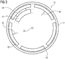
- the grinding shoes 39 are positioned on an extension 41 of the functional component 9 .
- the extension 41 is preferably provided as a ring, depending on the design of the rotor carrying structure 16, on the radially central part of the functional component 9.
- Several extensions 41 running on the same radius can also be provided there, as is also the case, for example, in 3 is indicated by dashed lines.
- either one or more magnetic rail brake assemblies 14 can be located in this area. This can serve to increase the braking force and/or to provide redundancy for the magnetic rail brake arrangement 14 .
- the magnetic rail brake arrangements 14 are integrated into the superordinate control concept of the wind turbine 1 .
- the magnetic rail brake arrangements 14 or, if there are several contact shoes 39, at least some contact shoes 39 can thus fulfill holding functions and also carry out service braking or emergency braking, which lead to the generator 7 and thus ultimately the wind turbine 1 coming to a standstill.
- Air cooling 28 can now easily be implemented via the NDE side 42 of the rotor 15 .
- air is sucked in in the outer region of the rotor 15 and guided through the cooling channels 31 axially through the laminated core 18 and/or the air gap 25 to the side of the rotor 15 facing the functional component 9 .
- the heated air is then discharged axially out of the rotor 15 on the NDE side 42 via the magnetic rail brake arrangement 14 and the space between the spokes 38 .
- the air outlet is therefore radially further inwards than the air inlet.
- the air flow of the air cooling 28 is generated either by an external fan and/or by appropriate design of the spokes 37.
- the spokes 37 are designed in such a way that either a suction or pressure effect is generated when the rotor 15 rotates.
- the stator 22 of the generator 7 has a laminated core in which a winding system 30 is arranged, which forms end windings 23 on the end faces of the stator 22 .
- the stator 22 is sealed by a can 24 at least on the side of the air gap 25 . Liquid cooling of the stator 22, in particular oil cooling 27, is thus possible.
- the functional component has on the side facing the functional component 9 9 means for positioning and / or a can seal 26 on.
- Cooling channels 32 of the stator 22 and/or also distribution channels are provided in or on the laminated core of the stator 22 and/or the slots of the stator 22 in the region of a winding system and/or on the side of the generator flange extension 11 facing the stator 22 . These can also run inside the generator flange extension 11 .
- the magnetic rail brake arrangement 14 is integrated into the superordinate control concept of the wind turbine 1 .
- the brake assemblies 14 can thus perform holding functions and service braking, but also emergency braking. In the case of a plurality of magnetic track brake assemblies 14 acting independently of one another, this can serve to increase the braking force and/or to provide redundancy for the magnetic track brake assembly 14 .
- Additional sensors 44 in or on the magnetic rail brake assembly 14 are connected to the higher-level control device 29 and can monitor both the braking force and wear and the number of braking operations, etc.
- the electrical actuation energy of the magnetic rail brake arrangement 14 is provided, for example, by a battery 38 which is arranged in the gondola 8, in particular in the vicinity of the generator-gear unit 26.
- the described structure of the generator-gear unit according to the invention with the functional component 9 according to the invention ensures a compact design, particularly in the axial direction.
- the generator 7 is overhung, so that no end shield is to be provided on the NDE side 42.
- Only one cover 21 can be provided, which has corresponding air outlet and air inlet openings. This cover 21 is preferably made of GRP.
- the actuating energy of the respective magnetic track brake assemblies 14 is provided, for example, by a battery 38, which is advantageously arranged in the vicinity of the functional component 9, for example the generator flange extension 11 and/or the transmission flange extension 12.
- This magnetic rail brake arrangement 14 is controlled and activated or deactivated either by a superordinate control structure 29 or manually.
- the braking surface 43 is shown on the inside of the hollow cylinder 17.
- the braking surfaces 43 can also be designed as rails, which point radially inwards from the inside of the hollow cylinder 17 .
- Contact shoes 39 which in the illustrated case are still at a distance from the braking surface 43, press outwards in direction 40 when actuated and thus generate the desired braking effect of the rotor 15 and thus of the transmission 6 and ultimately of the wind turbine 1 through friction on the braking surface 43.
- Grinding shoes 39 and braking surfaces 43 or rails are complementary to one another in order to achieve the highest possible braking force.
- actuators 30 are provided on the extension(s) 41, for example, which, when actuated accordingly, bring about a radial movement of the grinding shoes 39 in direction 40 onto the braking surface 43.
- the magnetic rail brake arrangement 14 can have one or more contact shoes 39--in the present case five contact shoes 39--which can be controlled jointly or individually.
- the interior of the rotor can also be closed off comparatively easily by a cover 21 .
- stator 22 and the transmission 6 have oil cooling. Separate cooling circuits but also a common cooling circuit are conceivable.
- the rotor 15 of the generator 7 is cooled by air.
- laminated cores of the stator 22 and/or rotor 15 can be stacked axially throughout. However, laminated cores can be implemented both in the stator 22 and/or in the rotor 15, which are composed of a plurality of partial laminated cores that are spaced apart axially in order to create additional radial cooling gaps.
- a rotary dynamoelectric machine preferably an asynchronous machine or a synchronous machine, is provided as the generator 7 . Numbers of pole pairs from two to thirty are conceivable.
- Gear ratios between the wind rotor shaft 4 and the rotor 15 of the generator are aimed at, depending on the design, from 20 to 200.
- the transmission 6 and the generator 7 are arranged in particular axially separately from one another are. It is important that at least components of the magnetic rail brake arrangement 14 are arranged at least partially within the rotor 15 and/or the stator 22 when viewed axially.
- the braking torques achieved are greater the greater the distance between the hollow cylinder 17 and thus the braking surface 43 from the transmission output shaft 34 .
- a brake arrangement in particular a magnetic rail brake arrangement 14, axially within the generator 7--can also be implemented in particular with directly driven internal-rotor generators of a wind turbine 1.
Landscapes
- Engineering & Computer Science (AREA)
- Power Engineering (AREA)
- Life Sciences & Earth Sciences (AREA)
- Sustainable Energy (AREA)
- Sustainable Development (AREA)
- Combustion & Propulsion (AREA)
- Chemical & Material Sciences (AREA)
- Mechanical Engineering (AREA)
- General Engineering & Computer Science (AREA)
- Physics & Mathematics (AREA)
- Electromagnetism (AREA)
- Wind Motors (AREA)
- Connection Of Motors, Electrical Generators, Mechanical Devices, And The Like (AREA)
Priority Applications (5)
| Application Number | Priority Date | Filing Date | Title |
|---|---|---|---|
| EP20211250.4A EP4008898A1 (fr) | 2020-12-02 | 2020-12-02 | Agencement d'engrenage et de générateur d'une éolienne comprenant un frein |
| EP21820539.1A EP4256199B1 (fr) | 2020-12-02 | 2021-11-26 | Agencement d'engrenage et de générateur comprenant un frein pour éolienne |
| CN202180081334.4A CN116648557A (zh) | 2020-12-02 | 2021-11-26 | 带制动器的用于风力发电设备的发电机/齿轮箱装置 |
| PCT/EP2021/083149 WO2022117452A1 (fr) | 2020-12-02 | 2021-11-26 | Agencement générateur/multiplicateur pour installation d'énergie éolienne pourvue d'un frein |
| US18/036,317 US11891981B2 (en) | 2020-12-02 | 2021-11-26 | Generator/gearbox arrangement for a wind power installation with a brake |
Applications Claiming Priority (1)
| Application Number | Priority Date | Filing Date | Title |
|---|---|---|---|
| EP20211250.4A EP4008898A1 (fr) | 2020-12-02 | 2020-12-02 | Agencement d'engrenage et de générateur d'une éolienne comprenant un frein |
Publications (1)
| Publication Number | Publication Date |
|---|---|
| EP4008898A1 true EP4008898A1 (fr) | 2022-06-08 |
Family
ID=73694849
Family Applications (2)
| Application Number | Title | Priority Date | Filing Date |
|---|---|---|---|
| EP20211250.4A Withdrawn EP4008898A1 (fr) | 2020-12-02 | 2020-12-02 | Agencement d'engrenage et de générateur d'une éolienne comprenant un frein |
| EP21820539.1A Active EP4256199B1 (fr) | 2020-12-02 | 2021-11-26 | Agencement d'engrenage et de générateur comprenant un frein pour éolienne |
Family Applications After (1)
| Application Number | Title | Priority Date | Filing Date |
|---|---|---|---|
| EP21820539.1A Active EP4256199B1 (fr) | 2020-12-02 | 2021-11-26 | Agencement d'engrenage et de générateur comprenant un frein pour éolienne |
Country Status (4)
| Country | Link |
|---|---|
| US (1) | US11891981B2 (fr) |
| EP (2) | EP4008898A1 (fr) |
| CN (1) | CN116648557A (fr) |
| WO (1) | WO2022117452A1 (fr) |
Families Citing this family (2)
| Publication number | Priority date | Publication date | Assignee | Title |
|---|---|---|---|---|
| US12603551B2 (en) * | 2023-06-07 | 2026-04-14 | Hamilton Sundstrand Corporation | Hybrid liquid and air cooling of high-power permanent magnet machine rotor |
| DE102023212319A1 (de) * | 2023-12-07 | 2025-06-12 | Zf Friedrichshafen Ag | Rotornabe mit Langlöchern |
Citations (3)
| Publication number | Priority date | Publication date | Assignee | Title |
|---|---|---|---|---|
| US8376708B2 (en) | 2009-06-30 | 2013-02-19 | General Electric Company | Drivetrain system for a wind turbine generator and method of assembling the same |
| FR3016252A1 (fr) * | 2014-01-07 | 2015-07-10 | Dcns | Dispositif de transformation d'energie mecanique en energie electrique, notamment pour une eolienne |
| DE102018100951A1 (de) * | 2018-01-17 | 2019-07-18 | Wobben Properties Gmbh | Arretier- und Bremsmodul für eine Windenergieanlage sowie Generator und Windenergieanlage mit selbigem |
Family Cites Families (12)
| Publication number | Priority date | Publication date | Assignee | Title |
|---|---|---|---|---|
| US519674A (en) * | 1894-05-08 | heilmann | ||
| US895618A (en) * | 1906-11-20 | 1908-08-11 | Leonard K Clark | Power-transmitting device. |
| US3723795A (en) * | 1971-07-12 | 1973-03-27 | M Baermann | Eddy-current and hysteresis brake for track-bound vehicles |
| US4738148A (en) * | 1984-12-12 | 1988-04-19 | Peter Norton | Starter drive |
| DE4402184C2 (de) * | 1994-01-26 | 1995-11-23 | Friedrich Prof Dr Ing Klinger | Vielpol-Synchrongenerator für getriebelose Horizontalachsen-Windkraftanlagen mit Nennleistungen bis zu mehreren Megawatt |
| RU2216469C1 (ru) * | 2002-07-15 | 2003-11-20 | Елецкий государственный университет им.И.А.Бунина | Электромагнитный рельсовый тормоз |
| US7948100B2 (en) * | 2007-12-19 | 2011-05-24 | General Electric Company | Braking and positioning system for a wind turbine rotor |
| US7884493B2 (en) * | 2008-09-30 | 2011-02-08 | General Electric Company | Wind turbine generator brake and grounding brush arrangement |
| CN201963479U (zh) * | 2010-12-30 | 2011-09-07 | 珠海宏锋风能科技有限责任公司 | 风力发电机电磁刹车装置 |
| DE102012010898A1 (de) * | 2012-06-01 | 2013-12-05 | Knorr-Bremse Gmbh | Magnetschienenbremsvorrichtung |
| US20140110947A1 (en) * | 2012-10-24 | 2014-04-24 | Vestas Wind Systems A/S | Wind turbine generator having an eddy current brake, wind turbine having such a generator, and associated methods |
| US10054204B2 (en) * | 2017-01-09 | 2018-08-21 | Richard Harper | Variable output planetary gear set with electromagnetic braking |
-
2020
- 2020-12-02 EP EP20211250.4A patent/EP4008898A1/fr not_active Withdrawn
-
2021
- 2021-11-26 WO PCT/EP2021/083149 patent/WO2022117452A1/fr not_active Ceased
- 2021-11-26 US US18/036,317 patent/US11891981B2/en active Active
- 2021-11-26 EP EP21820539.1A patent/EP4256199B1/fr active Active
- 2021-11-26 CN CN202180081334.4A patent/CN116648557A/zh active Pending
Patent Citations (3)
| Publication number | Priority date | Publication date | Assignee | Title |
|---|---|---|---|---|
| US8376708B2 (en) | 2009-06-30 | 2013-02-19 | General Electric Company | Drivetrain system for a wind turbine generator and method of assembling the same |
| FR3016252A1 (fr) * | 2014-01-07 | 2015-07-10 | Dcns | Dispositif de transformation d'energie mecanique en energie electrique, notamment pour une eolienne |
| DE102018100951A1 (de) * | 2018-01-17 | 2019-07-18 | Wobben Properties Gmbh | Arretier- und Bremsmodul für eine Windenergieanlage sowie Generator und Windenergieanlage mit selbigem |
Also Published As
| Publication number | Publication date |
|---|---|
| EP4256199A1 (fr) | 2023-10-11 |
| EP4256199B1 (fr) | 2024-08-14 |
| US20230392579A1 (en) | 2023-12-07 |
| CN116648557A (zh) | 2023-08-25 |
| WO2022117452A1 (fr) | 2022-06-09 |
| US11891981B2 (en) | 2024-02-06 |
Similar Documents
| Publication | Publication Date | Title |
|---|---|---|
| EP2419630B1 (fr) | Éolienne et dispositif d'entraînement pour le réglage d'une pale de rotor | |
| EP2413483A1 (fr) | Moteur électrique pour aéronef | |
| EP2380666B1 (fr) | Système d'entraînement de moulin | |
| WO2013045199A2 (fr) | Système d'entraînement pour éolienne | |
| DE102014224476A1 (de) | Elektrische Antriebseinheit, Hybridantriebseinrichtung und Fahrzeug | |
| EP2295147A1 (fr) | Système d'entraînement de moulin | |
| EP2853021A2 (fr) | Générateur synchrone optimisé d'une éolienne à entraînement direct | |
| EP4256199B1 (fr) | Agencement d'engrenage et de générateur comprenant un frein pour éolienne | |
| DE102017214412A1 (de) | Direktantrieb bei Rollen, Walzen und Winden in der Stahl/NE-Industrie | |
| EP3308449B1 (fr) | Anneau de stator pour générateur électrique et générateur et éolienne équipé de celui-ci | |
| EP3107192B1 (fr) | Pompe à vide | |
| EP2445090A1 (fr) | Machine dynamoélectrique dotée d'un dispositif de frein d'arrêt | |
| EP2226920A2 (fr) | Système de cogénération avec un moteur à combustion à piston et une machine électrique | |
| WO2011141511A2 (fr) | Machine électrique, destinée en particulier à une éolienne | |
| AT512853B1 (de) | Differentialantrieb für eine Energiegewinnungsanlage | |
| DE10310777A1 (de) | Elektromaschine mit koaxialen, mehrfach abwechselnden Magnet- und Wicklungslagen | |
| EP3740673B1 (fr) | Module d'arrêt et de freinage d'une éolienne ainsi que générateur et éolienne munis dudit module | |
| DE102011000420B4 (de) | Turbo-Generator-Einheit | |
| EP3889425A1 (fr) | Unité de transmission et de générateur d'une éolienne | |
| EP3990793B1 (fr) | Moteur électrique vidangé comprenant un palier à roulement pour un véhicule à moteur | |
| CA3036124A1 (fr) | Dispositif d'arret de rotor pour une eolienne et procede | |
| WO2026037615A1 (fr) | Chaîne cinématique pour un véhicule ferroviaire | |
| WO2022214144A1 (fr) | Stator de moteur d'entraînement électrique et moteur d'entraînement électrique | |
| DE102012003975A1 (de) | Triebstrang und Windenergieanlage | |
| WO2026002593A1 (fr) | Système d'entraînement compact pour une courroie transporteuse |
Legal Events
| Date | Code | Title | Description |
|---|---|---|---|
| PUAI | Public reference made under article 153(3) epc to a published international application that has entered the european phase |
Free format text: ORIGINAL CODE: 0009012 |
|
| STAA | Information on the status of an ep patent application or granted ep patent |
Free format text: STATUS: THE APPLICATION HAS BEEN PUBLISHED |
|
| AK | Designated contracting states |
Kind code of ref document: A1 Designated state(s): AL AT BE BG CH CY CZ DE DK EE ES FI FR GB GR HR HU IE IS IT LI LT LU LV MC MK MT NL NO PL PT RO RS SE SI SK SM TR |
|
| STAA | Information on the status of an ep patent application or granted ep patent |
Free format text: STATUS: THE APPLICATION IS DEEMED TO BE WITHDRAWN |
|
| 18D | Application deemed to be withdrawn |
Effective date: 20221209 |