EP2420428A1 - Pivot et châssis, notamment structure de poussette, comprenant le pivot - Google Patents
Pivot et châssis, notamment structure de poussette, comprenant le pivot Download PDFInfo
- Publication number
- EP2420428A1 EP2420428A1 EP10008567A EP10008567A EP2420428A1 EP 2420428 A1 EP2420428 A1 EP 2420428A1 EP 10008567 A EP10008567 A EP 10008567A EP 10008567 A EP10008567 A EP 10008567A EP 2420428 A1 EP2420428 A1 EP 2420428A1
- Authority
- EP
- European Patent Office
- Prior art keywords
- gear
- housing half
- disc
- half cover
- trigger
- Prior art date
- Legal status (The legal status is an assumption and is not a legal conclusion. Google has not performed a legal analysis and makes no representation as to the accuracy of the status listed.)
- Granted
Links
- 230000002441 reversible effect Effects 0.000 claims abstract description 5
- 230000000295 complement effect Effects 0.000 claims description 16
- 238000007373 indentation Methods 0.000 claims description 16
- 125000006850 spacer group Chemical group 0.000 claims description 15
- 230000006835 compression Effects 0.000 claims description 14
- 238000007906 compression Methods 0.000 claims description 14
- 230000003993 interaction Effects 0.000 claims description 14
- 230000033001 locomotion Effects 0.000 claims description 9
- 230000009466 transformation Effects 0.000 claims description 3
- 230000015572 biosynthetic process Effects 0.000 claims description 2
- 230000000630 rising effect Effects 0.000 claims description 2
- 229910052751 metal Inorganic materials 0.000 description 6
- 239000002184 metal Substances 0.000 description 6
- FYYHWMGAXLPEAU-UHFFFAOYSA-N Magnesium Chemical compound [Mg] FYYHWMGAXLPEAU-UHFFFAOYSA-N 0.000 description 4
- 229910052749 magnesium Inorganic materials 0.000 description 4
- 239000011777 magnesium Substances 0.000 description 4
- 229910052782 aluminium Inorganic materials 0.000 description 3
- XAGFODPZIPBFFR-UHFFFAOYSA-N aluminium Chemical compound [Al] XAGFODPZIPBFFR-UHFFFAOYSA-N 0.000 description 3
- 238000010276 construction Methods 0.000 description 3
- 238000000034 method Methods 0.000 description 3
- 230000035515 penetration Effects 0.000 description 3
- 238000003825 pressing Methods 0.000 description 3
- 230000008569 process Effects 0.000 description 3
- 230000008901 benefit Effects 0.000 description 2
- 230000008878 coupling Effects 0.000 description 2
- 238000010168 coupling process Methods 0.000 description 2
- 238000005859 coupling reaction Methods 0.000 description 2
- 230000000881 depressing effect Effects 0.000 description 2
- 239000000463 material Substances 0.000 description 2
- 238000003860 storage Methods 0.000 description 2
- 229920002430 Fibre-reinforced plastic Polymers 0.000 description 1
- 230000005540 biological transmission Effects 0.000 description 1
- 239000000969 carrier Substances 0.000 description 1
- 230000000994 depressogenic effect Effects 0.000 description 1
- 238000004512 die casting Methods 0.000 description 1
- 238000009826 distribution Methods 0.000 description 1
- 229940079593 drug Drugs 0.000 description 1
- 239000003814 drug Substances 0.000 description 1
- 239000011151 fibre-reinforced plastic Substances 0.000 description 1
- -1 for example Substances 0.000 description 1
- 230000007246 mechanism Effects 0.000 description 1
- 229910001092 metal group alloy Inorganic materials 0.000 description 1
- 238000004091 panning Methods 0.000 description 1
- 230000002093 peripheral effect Effects 0.000 description 1
- 239000004033 plastic Substances 0.000 description 1
- 229920003023 plastic Polymers 0.000 description 1
- 230000006641 stabilisation Effects 0.000 description 1
- 238000011105 stabilization Methods 0.000 description 1
Images




Classifications
-
- B—PERFORMING OPERATIONS; TRANSPORTING
- B62—LAND VEHICLES FOR TRAVELLING OTHERWISE THAN ON RAILS
- B62B—HAND-PROPELLED VEHICLES, e.g. HAND CARTS OR PERAMBULATORS; SLEDGES
- B62B7/00—Carriages for children; Perambulators, e.g. dolls' perambulators
- B62B7/04—Carriages for children; Perambulators, e.g. dolls' perambulators having more than one wheel axis; Steering devices therefor
- B62B7/06—Carriages for children; Perambulators, e.g. dolls' perambulators having more than one wheel axis; Steering devices therefor collapsible or foldable
- B62B7/08—Carriages for children; Perambulators, e.g. dolls' perambulators having more than one wheel axis; Steering devices therefor collapsible or foldable in the direction of, or at right angles to, the wheel axis
-
- B—PERFORMING OPERATIONS; TRANSPORTING
- B62—LAND VEHICLES FOR TRAVELLING OTHERWISE THAN ON RAILS
- B62B—HAND-PROPELLED VEHICLES, e.g. HAND CARTS OR PERAMBULATORS; SLEDGES
- B62B7/00—Carriages for children; Perambulators, e.g. dolls' perambulators
- B62B7/04—Carriages for children; Perambulators, e.g. dolls' perambulators having more than one wheel axis; Steering devices therefor
- B62B7/06—Carriages for children; Perambulators, e.g. dolls' perambulators having more than one wheel axis; Steering devices therefor collapsible or foldable
- B62B7/062—Coupling unit between front wheels, rear wheels and handle
-
- B—PERFORMING OPERATIONS; TRANSPORTING
- B62—LAND VEHICLES FOR TRAVELLING OTHERWISE THAN ON RAILS
- B62B—HAND-PROPELLED VEHICLES, e.g. HAND CARTS OR PERAMBULATORS; SLEDGES
- B62B2205/00—Hand-propelled vehicles or sledges being foldable or dismountable when not in use
- B62B2205/18—Geared articulations
Definitions
- the present invention relates to a pivot bearing, in particular for a stroller frame, a chassis, in particular stroller frame, comprising at least one such pivot bearing, and the use of this pivot bearing for chassis.
- Collapsible stroller frames have long been known. They make it possible to stow away and transport prams to save space.
- An embodiment of a collapsible stroller frame is found, for example, in US Pat DE 699 26 041 T2 described.
- U 1 is a rotary joint with a locking device for pivotally connecting at least two stroller support struts out.
- This swivel joint comprises at least a first and at least one second swivel element, wherein the second swivel element on an annular flange which is rotatably mounted concentrically in a bearing shell in the first swivel element on the circumference at least one bearing point for a pivotable pawl, by the force of a spring at least one latching element provided as a latching element is supported on the inner surface of the bearing shell of the first rotary joint element.
- the first swivel element does not have internal teeth in the bearing shell over a defined swivel angle range.
- a push button with at least one disengagement bevel has to be mounted displaceably against the force of a spring on the outside of the disk-shaped cover wall, the spring acting on the detent when actuated such that the detent protrudes out of the toothing , whereby the second pivot element is rotatable relative to the first.
- the DE 20 2008 013 777 U1 relates to a swivel for a stroller with at least two successive hinge elements, which are secured against rotation by a cylindrical, axially displaceable locking element with an external toothing, which is in engagement with an internal toothing.
- the external toothing of the locking element is so wide that in each case the internal teeth of at least two connecting parts in the locked position bridged and are completely displaceable from a joint element in the adjacent.
- the locking element is supported by a compression spring on one side and by a displaceable plunger or by a pushbutton on the other side.
- the plunger or the push button can be fixed in the depressed position by means of a releasable locking device on the joint element. With this device, a relative pivoting of a joint element with respect to a further joint element to succeed, without having to hold down a plunger or a push-button simultaneously.
- a collapsible sliding carriage for children or dolls out with a collapsible frame comprising a first and a second pivot bearing, which are operatively connected to each other via a coupling gear, which is designed such that when Vorschwenken the push rod in the direction of the front support strut by rotational movement transformation, the rear Support strut is automatically pivoted forward in the direction of the front wheel.
- the coupling gear has a rotatably mounted on the pivot axis of the first pivot bearing for the sliding rod with at least partially on Have disc periphery provided pinions, which is also rotatable about a mounted on the push rod driver when turning the push rod.
- the pinion engages in a contour-adapted toothing of an at least segmented ring gear on the rear support strut.
- the rear strut is attached to the sprocket and this in turn to the second pivot bearing.
- the present invention is therefore based on the object to provide collapsible stroller racks, which are no longer subject to the disadvantages of the prior art and in particular easy to use in a user-friendly way and collapsible and also unfolded and preferably in the folded Condition take a least possible storage volume and can be safely stored in a compact form.
- a pivot bearing in particular for a chassis, such as stroller rack, found, comprising a first housing half cover with an inside and an outside, comprising a first and a second portion and containing a first receiving part or connected or connectable with a first receiving part for a first strut, in particular front strut of a stroller frame, and, present or attached or attachable on or on the inside spaced apart first and second means, suitable and adapted to form substantially rectified first and second axes, in particular comprising at least a first or second connecting element and / or at least one first and second bearing element, for example, first and second substantially rectified sleeves and / or stub shafts; a second housing half cover adapted and adapted to form a first sub housing with the first subsection of the first housing half cover, having an inner and an outer side containing a second or connected to a second housing Receiving part for a second strut, in particular pusher rod of a driving or stroller frame, and one, present or attached or attachable to or
- first trigger gear disc can be brought into interaction with the second trigger gear disc, in particular when the first latch disc and the first gear disc are unlocked or decoupled. Furthermore, it can be provided that the first gear disk and the second gear disk can be brought into interaction, in particular when the second locking disk and the second gear disk are unlocked or decoupled.
- the first and the third device also called axle-forming device, or the second and the fourth device, also called axle-forming device, can be used e.g. represent a sleeve / mandrel combination, a mandrel / sleeve combination, or a screw thread / screw or screw / screw thread combination. It is also possible to obtain the first or second axis by a first and third means or by a second and fourth means in which a sleeve is slipped over or slipped over one or two mandrels to form an axis.
- first and third means and the second and fourth means may also comprise a screw and a sleeve, wherein the sleeve is mounted on the screw to obtain said axis or axis of rotation.
- a rivet can also be used for the attachment or storage of the sleeve.
- the sleeve and the mandrel are also understood as a bearing element and the screw, the rivet and the mandrel as a connecting element.
- first, second, third and fourth means may constitute bearing and connecting elements for the formation of first and second axes, respectively.
- pivot bearing according to the invention may be designed such that the first means for forming the first axis in the first section and that the second means for forming the second axis in the second section is present.
- the first axis in the first section and the second axis in the second section of the first housing half cover is provided.
- At least the first housing half cover and / or the first toothed wheel disc are at least partially made of a metal, in particular aluminum or magnesium, e.g. Magnesium die casting, are made.
- all the housing half covers of the pivot bearing according to the invention can be partially or completely made of a metal.
- only the first housing half cover is partially or completely made of a metal, in particular aluminum or magnesium.
- components not made of metal or metal alloys can be used in the pivot bearing according to the invention readily on those of plastic materials, for example, fiber-reinforced plastic materials.
- the first housing half cover preferably lies facing the interior of the chassis or the seat or the bath tub.
- the first receiving part is part or connected or connectable with the first part section.
- This receiving part preferably takes on the front strut of a chassis, in particular pushchair on.
- the first section of the first housing half cover is preferably provided with a receiving part which receives the pivot slide or the pivot slide strut, and the second section of the first housing half cover is preferably provided with a receiving part which receives the support strut for the rear wheel.
- the first and the second section of the first Gezzausekorlfienabdeckung are preferably made in one piece.
- the first housing half cover is in one piece.
- the first housing half cover of the pivot bearing according to the invention is designed such that it contributes significantly to the stability of the entire pivot bearing.
- Inventive pivot bearings may also provide that the side facing away from the inside of the first housing half cover side of the first locking disc has at least one, preferably at least three, first protrusions or indentations or inlets and in that the adjacent side of the first toothed wheel disk is provided with at least one, preferably at least three, notches or bulges complementary thereto, which can be brought into engagement with one another. Two adjacent indentations or bulges regularly occupy an angle greater than 0 ° relative to each other.
- the first bulges or indentations of the first locking disk and the notches or bulges of the first gear disk complementary thereto preferably have substantially accurately fitting counterforms.
- the first bulge of the first locking disc can be inserted or inserted into the complementary notch of the first toothed wheel disc.
- the first protrusions preferably extend radially, e.g. starting from or adjacent to the receiving hole of the first axis to or adjacent to the outer edge of the first locking disk and are preferably arranged substantially in a straight line.
- Such adjacent indentations include an angle which is preferably in the range of 70 to 120 °.
- the second locking disk may also be made for the second locking disk to have at least one, preferably at least three, second indentations or indentations on the side facing away from the inside of the first housing half cover and for the side of the second gear wheel facing this side to have at least one , preferably
- At least three, complementary to this bulges or notches is provided which are engageable with each other.
- Two adjacent indentations or bulges regularly occupy an angle greater than 0 ° relative to each other.
- Notches or the complementary bulges can e.g. take the form of half-cylinders, hemispheres, circular arcs or the like.
- At least one pivoting angle formed by two adjacent first notches / inlets or bulges in the range from 75 ° to 150 ° and preferably from 80 ° to 120 °, and particularly preferably from 90 ° to 110 ° and in particular in the range of 95 ° to 105 °.
- the angle that occupy the first, second and third receiving parts relative to each other can be determined in an expedient embodiment, the angle that occupy the first, second and third receiving parts relative to each other can.
- the bulges and the notches complementary thereto are radially aligned, for example in the form of half-cylinders or cuboids.
- Schwenklager according to the invention may also provide that the first gear is a partial gear, preferably on its circumference gears along a center angle in the range of 30 ° to 60 °, in particular in the range of 35 ° to 50 °, and / or that the second gear a full gear or a partial gear, which has on its circumference gears preferably along a center angle in the range of 30 ° to 60 °, in particular in the range of 35 ° to 50 °.
- the first trigger gear disk is a partial gear wheel, which preferably has gear teeth along its periphery along a center angle in the range of 30 ° to 60 °, in particular in the range of 35 ° to 50 °
- the second trigger gear disk is a full gear or a partial gear wheel, which preferably has gearwheels along its circumference in the range of 30 ° to 60 °, in particular in the range of 35 ° to 50 °, along its circumference.
- the first actuating or fastening device for a cable or Bowden cable is on the side of the first trigger gear disc, which faces away from the inside of the first housing half cover.
- the first trigger gear disc of the pivot bearing according to the invention on the side facing away from the inside of the first housing half cover, via a driving device which is designed and arranged to interact with the second actuating or fastening device of the trigger.
- first toothed wheel disc at least two first connection points spaced on the inside of the second housing half cover is non-rotatably fastened or attachable via fastening means, in particular bolts or locking pins.
- fastening means in particular bolts or locking pins.
- spacers in particular adjacent to the circumference of the first gear wheel, are present, which are preferably suitable and adapted to receive fastening means.
- the first locking disc against rotation in particular the first portion, the first housing half cover is connected and arranged axially reversibly displaceable on the first axis.
- the second locking disc against rotation in particular the second portion, the first housing half cover is connected and axially reversibly slidably disposed on the second axis.
- Inventive pivot bearings may further provide that the first trigger gear disc adjacent to the circumference at least two, in particular four, first punctures, each passing through a first piercing a first spacer and wherein these first punctures are formed such that the first trigger gear wheel to the first Axis is partially rotatable.
- the perforations in number, size and / or shape are formed and that the corresponding spacers are arranged on the first gear wheel such that the first trigger gear disc at least by a circumferential angle of 25 °, in particular from 25 ° to 60 ° and particularly preferably from 35 ° to 50 °, for example 42 °, about the first axis is rotatable.
- Inventive pivot bearings may also be characterized in that the second trigger gear disc adjacent to the circumference at least two, in particular four, second punctures, wherein passing through a second piercing a second spacer and wherein these second punctures are formed such that the second trigger gear wheel to the second axis is partially rotatable.
- the second punctures in number, size and / or shape are formed and that the second spacers are arranged on the second toothed wheel such that the second trigger toothed wheel at least by a circumferential angle of 25 °, in particular from 25 ° to 60 ° and more preferably from 35 ° to 50 °, for example 42 °, about the second axis is rotatable.
- the first unlocking device is present on the side of the trigger, which faces the first locking disk, and a sequence of circumferential beveled Entriegelungszähne, in particular seven beveled Entriegelungszähne comprises.
- the sequence of circumferential beveled unlocking teeth may be a ring gear, for example a ring gear with an oblique toothing.
- a ring gear can also be toothed only segmented.
- the / the beveled Entriegelungszähne interacts with the beveled bearing surfaces of the first decoupling device in such a way that these beveled Entriegelungszähne each along the tapered bearing surfaces of the first decoupling device upon actuation of the trigger along, but without the End of the tapered bearing surface to get out. That is, the trigger is rotated only to a degree about the first axis that its unlocking teeth always only with the corresponding corresponding beveled bearing surfaces of the first decoupling device interact, skipping the Entriegelungszähne on each subsequent tapered bearing surface of the first decoupling device thus does not occur.
- the protrusions of the first detent disk are pushed out of the complementary notches or inlets of the first gear disk or the protrusions of the first gear disk out of the complementary notches of the first detent disk, so that the first locking disk and the first gear wheel can be rotated relative to each other.
- This twisting process is facilitated by the fact that the bulges and / or indentations or inlets in the direction of rotation at least partially have beveled or rounded bearing surfaces. This makes it particularly efficient to move the bulges completely out of the complementary notches or inlets.
- the first and / or second bulges of the first and second locking disk of the pivot bearing according to the invention can accordingly each have adjacent to the maximum extent of the bulge in the direction of rotation over at least one bevelled surface. Such a configuration of the first and second bulges of the first and second locking disk is preferred.
- the inside of the second housing half cover of the inventive pivot bearing may have a first stop for the second actuating or fastening device.
- the pivot bearing according to the invention may further provide that the trigger spaced from the second actuating or fastening device comprises a first actuating or fastening device which with a on the inside of the second housing half cover fastened or fixed elastic means, such as a train, Compression or torsion spring, connectable or connected.
- a first actuating or fastening device which with a on the inside of the second housing half cover fastened or fixed elastic means, such as a train, Compression or torsion spring, connectable or connected.
- elastic means such as a compression, tension or torsion spring
- pivot bearings are preferred in which the beveled Entriegelungszähne of the ring gear on a circumference, in particular circumference, are arranged and increases the slope of the slopes in such a way that at one operation of the cable or Bowden cable, with the second actuating or The fastener is operatively connected, the trigger rotates on the first axis such that the slope moves in the direction of rotation and that the high point of the slope runs in the direction of the position of the low point of the associated slope, which it has previously occupied.
- the pivot bearing according to the invention may provide in one embodiment that the first and the second gear disc are in a first plane in such a way that upon rotation of the first gear disc, the teeth of the same with the teeth of the second gear disc can be brought into engagement.
- first and the second trigger gear disc lie in a second plane in such a way that upon rotation of the first trigger gear disc, the teeth thereof with the teeth of the second trigger gear disc are engageable.
- the pivot bearing according to the invention allows that the slider strut, the Vorderradstützstrebe and the Schuradstützstrebe are arranged substantially parallel to each other.
- first latching disk and first gearwheel disk as well as second latching disk and second gearwheel disk are in the unlocked or decoupled state.
- first locking disk and / or first gear disk or second locking disk and / or second gear disk are in a locked state.
- the pivot bearings according to the invention are preferably used in chassis in such a way that the front wheel brace is rigidly attached to the pivot bearing housing, while the slider handle and the rear strut against each other rotatable, in particular in the direction of the Vorderradstützstrebe are rotatable.
- the trigger and the first gear wheel activated separately via the first and second actuator can be, for example, connected to these cables or Bowden cables.
- the trigger and the first gear wheel activated separately via the first and second actuator can be, for example, connected to these cables or Bowden cables.
- the first locking disk is decoupled from the first gear wheel, whereby the slider handle can be pivoted from a first detent position to a further detent position.
- the trigger is returned to its original position. This can be accomplished by the first compression spring pushing the first locking disk back into a corresponding locking position in the first toothed wheel disk.
- the pivot bearing according to the invention can now be used to fully collapse the slide handle, the Vorderradstützstrebe and Schuradstützstrebe.
- the first actuator of the first trigger gear disc is designed such that it has a driver which carries on actuation of the first actuator, for example via a cable or Bowden cable, the second actuator of the trigger.
- the first trigger gear disc for example, via a cable, which acts on the first actuator, set in rotation, is already offset in this way by the voltage applied to the driver second actuator of the trigger also in rotational motion.
- the pivot bearing according to the invention is characterized in a further development by a first holding device for a seat element, comprising a seat surface, or for a locking element for a seat, comprising a mounting bracket for mounting the seat and a handlebar or adjustment bar with a first and an opposite second End, wherein the first holding device rotatable about a first attachment point on the outside the first housing half cover is attached and stored and wherein the handle bar is rotatably mounted and supported at the first end about a second attachment point on the third receiving part and / or the third strut and wherein the second end of the handlebar or adjustment bar rotatable about a third attachment point is attached to the first holding device and is mounted, wherein the first holding device and the handlebar or adjusting bar and the first, second and third attachment point are set up and matched to one another such that when moving to each other from the first and third receiving part or from the first and third strut of the mounting bracket of the first holding device is reversibly movable such that a fastened to the mounting
- the third attachment point is always on the side of a line formed by the first and second attachment point, the
- first attachment point is present on the first portion and / or that the first attachment point is always less widely spaced in generic use of the pivot bearing of a line connecting the first and second axis, as the second attachment point.
- first attachment point is regularly above the second attachment point.
- a chassis in particular stroller frame comprising two mirror-symmetrically arranged to the longitudinal axis of the Fahr- or stroller frame, rising from front to back front support struts, at the lower ends, optionally with intermediate holders and / or bearings and / or axles, front wheels are attachable or present or which are equipped with a connecting bridge element to which, in particular centrally, at least one Front wheel is attached or attachable; two to the longitudinal axis of the carriage or stroller frame arranged in mirror image, in particular from back to front, extending rear struts, at the lower ends, optionally with interposed holders and / or bearings and / or axles, rear wheels are attached or present; two push rods, at the upper ends of individual push handles or a connecting push bar are attached or attached; a first inventive pivot bearing and a second pivot bearing according to the invention, wherein the front support struts are first struts and present in each of the first receiving parts of the first and second pivot bearing, wherein
- a stowed position are pivotable and wherein the pivot bearings are designed such that when Vorschwenken the push rods in the direction of the front strut by rotational movement transformation, the rear strut is automatically pivoted forward.
- Chassis for the purposes of the present invention include, in addition to strollers, among others doll dollies, rollators, tray cars, tool box carriers, wheelchairs, as well as chasses for the food distribution, e.g. in hospitals or day-care centers, or for dispensing medicines, e.g. in hospitals or retirement homes, and the like.
- the pivot bearing according to the invention for e.g. Folding chairs, folding chairs, folding tables and the like use.
- chassis in particular stroller racks
- pivot bearings according to the invention it is possible to collapse the support struts for front and rear wheels and the slide handle bars so far that they are all arranged parallel to each other.
- the pivot bearings according to the invention make it possible to fold up chassis, in particular stroller frames, in such a way that they can be stored on their folded narrow side, without the risk of tipping over.
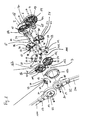
- FIG. 1 shows a schematic exploded view of the pivot bearing according to the invention.
- the pivot bearing 1 according to the invention has a first housing half cover 2, preferably made of a metal, particularly preferably of a light metal such as magnesium or aluminum.
- This first housing half cover 2 together with the second housing half cover 16 and the third housing half cover 26, provides the housings for the pivot bearing 1 according to the invention.
- the first housing half cover 2 can be divided into first and second sections 18 and 19, respectively.
- a first receiving part 8 is an integral part of the first portion 18 of the housing half cover 2. This first receiving part 8 is in the form of a sleeve or a nozzle and suitable for receiving the front strut of a chassis, such as a stroller frame.
- the second and third housing half covers 16 and 26 have a second and third receiving part 17, 32.
- the inventive pivot bearing 1 according to FIG. 1 takes the second receiving part 17 a slide rod of a chassis, in particular a stroller frame, and the third receiving part 32, the rear support strut of such a frame.
- the second receiving part 17 and the third receiving part 32 are each an integral part of the second or third housing half cover 16, 26. Sectionally shown are also embedded in the first receiving part 8 front support strut 10, in the second receiving part 17th recessed slider rod 110 and the recessed into the third receiving part 32 rear support strut 210th
- first housing half cover 2 is provided on its inner side 4 with first and second means 12 and 14, respectively, which serve to form the first and second axes.
- first device 12 is in the form of a sleeve on the inside of the first section 18.
- the second device 14 is located on the inside of the second portion 19 and is also formed in the illustrated embodiment in the form of a sleeve.
- these sleeves are an integral part of the housing half cover 2.
- the inner sides of the second and the third housing half cover are preferably equipped with corresponding means for forming the first and second axes and can also be in the form of rectified sleeves (see FIG. 2 , Reference numeral 151).
- first and third means 12 and 151 form receptacles for the first axis or are part of the first axis.
- second and fourth means are adapted to receive the second axis and form part of this second axis, respectively.
- first compression spring 34 On the first axis there is a first compression spring 34, which has a contact or abutment surface on the inner side 4 of the first section 18 of the first housing half cover 2. The opposite end of this compression spring 34 abuts against the first locking disc 36. The first compression spring 34 presses the first detent disk 36 against the first gear disk 38. On the side of the first gear disk 38 facing the first detent disk 36 there are first notches (not shown) leading to the first protrusions 62 on that side of the first detent disk 36, which is remote from the inside 4 of the first housing half cover 2, are engageable. In other words, via the compression spring 34, the first locking disc 36 and the first gear wheel 38 are coupled together when the bulges 62 are engaged in the corresponding notches.
- first decoupling device 37 Around the first bearing or receiving hole 82 of the first locking disk 36 around a first decoupling device 37 is provided, for example as in FIG. 1 shown in the form of successive beveled bearing surfaces or teeth.
- the first decoupling device 37 faces the first gear wheel 38.
- This first decoupling device 37 interacts with the trigger 42, which has a first unlocking device 46 on its side facing the first latching disc 36.
- This unlocking device 46 comprises a rim of beveled bearing surfaces, which are complementary to the tapered bearing surfaces of the first decoupling device 37 and interact with the latter.
- the size of the bearing surfaces 62 and their slope is be sized so that the producible between the first locking disc 36 and the first gear wheel 38 distance sufficient to extract the bulges 62 from the corresponding notches in the first gear wheel 38. In this way, first latching disk 36 and first gear disk 38 can then be relatively rotated against each other. Once the bulges 62 are no longer in engagement with the corresponding notches of the first gear wheel 38, the front and rear struts are rotated against each other.
- the first locking disc 36 is against rotation on the first axis. This can succeed, that, as in FIG. 1 shown, on the inside 4 of the first housing half cover 2, a plurality of first port 84 are present, which engage in first corresponding openings or holes 86 in the first locking disc 36.
- the trigger 42 is actuated via a cable or Bowden cable fastened to the second actuating or fastening device 44.
- This Bowden cable is preferably guided through the interior of the slider rod strut 110 as far as an actuator on or adjacent to the slider handle. In this way, the person pushing a stroller, for example, without having to release the slider handle, via the trigger 42, the first locking disc 36 and the first gear disc 38 decouple, whereby the slide rod 110 is pivotable relative to the front and rear support strut 10 and 210 until the bulge lands 62 snap into the next inlets in the first gear wheel 38.
- the first gear wheel 38 is fixedly connected to the inside of the second housing half cover 16. This is done via the first connection points 39. This may, as in FIG. 1 shown spaced holes in the gear wheel 38 act holes through which screws or similar fasteners are feasible. In this way, a non-rotatable mounting relative to the second housing half cover 16 succeeds, wherein the first attachment points 39 furthermore have first spacers 35, for example in the form of cylindrical attachments, so that the first gear wheel 38 does not directly contact the inside of the second housing half cover 16 or the first Trigger gear wheel 40 comes to rest, but between the inside of the second housing half cover 16 and the first gear wheel 38, the first trigger gear 40 on the first axis can be arranged and rotatably mounted.
- This trigger gear disc 40 has on its periphery a first partial sprocket, ie a first sprocket segment 120 comprising a plurality of adjacent gear teeth. This first sprocket segment 120 extends in the illustrated embodiment along a center angle of about 42 °. Like the first gear wheel 38, the first trigger gear disk 40 also has a third bearing hole 102. Like the second bearing hole 92 of the first gear disk 38, the third receiving hole 102 of the first trigger gear disk 40 is concentric and sized formed so that the trigger 42 can pass therethrough to interact with the first decoupling device 37. The first trigger gear disc 40 is rotatably supported by the trigger 42 on the first axis.
- first passages 45 are provided through which the first spacers 35 of the first Piercing points 39 protrude.
- the permissible through the passages 45 or rotation angle of the first trigger gear 40 is so matched to the same on the circumference of the first gear segment 120 that upon actuation of the first trigger gear 40, the teeth of this ring gear segment 120 can be brought into engagement with the second gear segment 122 of second trigger gear disc 54, which is present on the second axis.
- the first trigger gear disc 40 is actuated via a cable or Bowden cable, which is connected via a first actuating or fastening device 56 with the trigger gear disc 40.
- Bowden cable is preferably again guided through the interior of the slide rod strut 110 in the direction of the slide handle (not shown).
- the trigger gear 40 is rotated, wherein the first gear segment 120 is brought into engagement with the second gear segment 122 of the second trigger gear disc 54. That is, by the rotation of the first trigger gear disc 40, the second trigger gear disc 56 existing on the second axis is also rotated.
- the first and second gear segments 120, 122 are arranged relative to each other, that an engagement succeeds when the slide rod, as in FIG. 1 shown, forward, that is pivoted in the direction of the front wheels.
- a second unlocking device 132 which protrudes through the fifth bearing or receiving hole 112 of the second gear disc 52 to interact with the second decoupling device 51 of the second locking disc 50 in such interaction occur that the second bulge 66 on the second locking disc 50 from the complementary notches or inlets on the opposite side of the second gear wheel 52 exit.
- the second locking disc 50 is decoupled from the second gear disc 52 and the rear support strut 210 can be pivoted by further pivoting the slider handle strut 110 in the direction of the front support strut 10 also on this front support strut 10.
- first sprocket 38 is fixedly connected to second housing half cover 16
- second sprocket wheel is located 52 in the same way firmly connected to the third housing half cover 26 before.
- first toothed wheel this also succeeds in the case of the second toothed wheel 52 via second attachment points 53, for example in the form of holes for screws or similar attachment means in the second toothed wheel 52 and second spacers 57, preferably in the region of these second attachment points on that side of the toothed wheel disk 52, which faces the inside of the third housing half cover 26.
- the second gear wheel 52 is fixed against rotation on the second housing half cover 26 before.
- the second spacers 57 which come to rest on the inside of the second housing half cover 26, it is possible in any case to ensure a partial rotatability of the second trigger gear disk 54 on the second axis.
- second punctures 55 are provided, the each receive a second spacer 57 and ensure a required path or angle of rotation of the second trigger gear 54.
- the second detent disk 50 is anchored against rotation with the first housing half cover 2. This is done via cylindrical extensions 94 of the first housing half cover 2, which protrude through thereto corresponding second inlets or holes 96 in the second locking disc 50.
- a particular stability can in turn be generated by the fact that second indentations 98 on the circumference of the second detent disk 50 interact with projections corresponding thereto in the second partial section 19 of the first housing half cover 2.
- the second locking disc 50 remains axially displaceable along the second axis.
- a second compression spring 48 the second detent disk 50 is pressed against the second gear wheel 52.
- the housing of the pivot bearing 1 according to the invention is completed by a cover ring 150, which, if necessary, complements the third housing half cover 26 and leads to a comprehensive coverage of the present on the second axis components. That is, while the first section 18 of the first housing half cover 2 together with the second housing half cover 16 sufficiently encloses the components present on the first axis, this succeeds in the illustrated embodiment for the components present on the second axis preferably only by the inclusion of the cover ring 150, which interacts with the second section 19 of the first housing half cover 2.
- folding door strut 110 and rear support strut 210 collapses in the direction of Vorderradstützstrebe 10 when both the locking disc 36 and the first gear disc 38 and the second locking disc 50 unlocked with the second gear wheel 52 and decoupled.
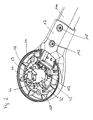
- FIG. 2 shows a perspective top view of the inside of the second housing half cover 16.
- the support strut 110 In the second receiving part 17 is the support strut 110 before. This strut second 110 may be connected by rivets or screws with the receiving part 17.
- the holes 162 and 164 provided for this purpose are shown.
- the trigger 42 On the third means 151 for forming the first axis in the form of a sleeve, which is present on the inside of the second housing half cover 16, the trigger 42 is placed.
- the trigger 42 is freely rotatable on the sleeve 151 and the first axis within certain limits.
- FIG. 2 also shows the first unlocking device 46 as part of the trigger 42, which is composed of a ring 47 of circumferential, beveled unlocking teeth 49. From the FIG.
- the screw receiving holes 168 for receiving bolts or rivets protrude, which fasten via the attachment points 39, the first gear disc 38 on the second housing half cover 16.
- About the slope and length of the tapered Entriegelungszähne 49 can be determined by which angle the trigger 42 is to rotate to decouple the first locking disc 36 of the first gear wheel 38. If this way is known, the maximum travel of the third actuator 72 may be limited by a first stop 123. In a corresponding manner, the range of motion of the second actuating or fastening device 44 can be limited by a second stop 174.
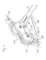
- FIG. 3 shows a perspective schematic plan view of an almost fully assembled according to the invention pivot bearing 1, but without the second housing half cover 16.
- the first gear wheel 38 rests on the first locking disc 36, and the first Tripping gear wheel 40 on the first gear wheel 38.
- the first connection points 39 and first spacer 43 of the first gear wheel 38 are respectively arranged in the first passages 45 of the first trigger gear disc 40.
- the dimensioning of the first penetrations 45 permits rotation of the first trigger gear disk 40 relative to the underlying first gear disk 38 by, for example, at least 25 degrees.
- the first trigger gear disc 40 can be actuated by operating a cable or Bowden cable, the actuating or fastening device 56 is located on the side facing away from the viewer side of the first trigger gear 40.
- the driver 167 ensures that the actuator or attachment device 44 for the cable or Bowden cable of the trigger 42 is automatically taken on actuation of the first actuator 56 of the first trigger gear 40, without having to be operated.
- the punctures 45 permit rotation of the first trigger gear disk 40 by about 40 to 42 degrees.
- the driver 167 here also includes the first actuator 56, for example, for a cable or Bowden cable (by dotted line indicated).
- the trigger 42, as well as the first gear disk 40 are to be rotated counterclockwise to decouple the slider handle or the rear wheel support brace, ie, to release it for rotation toward the front wheel support brace.
- both the slider handle and the rear wheel support strut are in locked, ie fixed position.
- the first actuator 44 of the trigger 42 is also set in motion counterclockwise. While the second detent disk is decoupled from the second toothed detent disk by actuation of the first trigger gear disk by means of the interaction with the second trigger gear disk, whereby the rear wheel support strut is released, the detent disk is decoupled from the first gear disk by actuation of the trigger by interaction with the first decoupling device of the first detent disk , whereby the slide handle strut is released.
- the decoupling of the first locking disc 36 and the first gear wheel 38 is effected by an unlocking tooth or unlocking teeth of the trigger on each corresponding beveled bearing surfaces of the first decoupling device 37 einwikrt without to the adjacent surface skip. That is, the unlocking tooth moves in the decoupling along the surface of a corresponding tapered surface only the The first decoupling device 37.
- FIG. 4 shows a section of a chassis, in particular stroller frame, comprising the pivot bearing 1 according to the invention, the slide handle bar 110, the front support strut 10 and the rear support strut 210.
- a first holding device 161 comprising a mounting bracket 162 for attachment of the seat or a locking device for the seat provided. That is, on the outside of the first housing half cover 2 is a first attachment point 166 for the first holding device 161 before.
- This holding device 161 is equipped with the mounting bracket 162 for the attachment of the seat.
- an adjustment bar 164 is attached to the third receiving part 32 for the rear support strut 210 via a second attachment point 168 at a first end thereof.
- the opposite end of the adjusting bar 64 is rotatably mounted and supported about a third attachment point 170 on the first holding device 161.
- the first holding device 161 and the adjusting bar 164 as well as the first, second and third attachment points 166, 168 and 170 are set up and matched to one another such that when the first and third supporting struts 10, 210 are moved toward one another, the fixing bracket 162 of the first holding device 161 is reversibly movable in this way in that a seat element fastened or fastened to the mounting bracket 162 optionally via a locking device assumes an orientation in the folded state of the pivot bearing in which its seat surface is substantially rectified with the first and / or third strut, in particular with the front and / or rear strut , is present.
- FIG. 5 shows a stroller 111 according to the invention, which is equipped with two pivot bearings 1, 1 'according to the invention.
- the seat is over in FIG. 4 shown holding device respectively connected to the mutually facing sides of the first housing half covers of the pivot bearing according to the invention.
- the first cable By operating the first cable, the first locking disc is decoupled from the first gear disc and the slider handle can be pivoted to a locking position to the front, as in FIG. 6 shown.
- By operating the second cable is the interaction of the first and second trigger gear disc, the second locking disk decoupled from the second gear wheel.
- FIG. 7 shows the stroller available through the described collapsing process.
- the front and rear struts and the pusher rods are all aligned substantially parallel, resulting in a very compact collapsed construction.
- the degree of compactness can be further increased by making the slider handle hinged by means of joints (see FIG. 8 ) and that you can also fold down the backrest of the seat on the seat. In this way it is even possible to store the folded stroller or the folded stroller frame free-standing upright, as in FIG. 9 shown.
- a particularly stable collapsed construction can be obtained by releasably locking the folded-back slider handle on the seat construction.
- Particular stability of the stroller according to the invention or the stroller frame according to the invention also receives the fact that in the folded state, the respective slide rods and struts by the engagement of the first locking disc and the first gear disc and second detent disc and second gear disc are present without swinging. Only by operating the cable for the first trigger gear disc second locking disc and second gear disc are decoupled again, whereby the slide rods and the rear support struts can be pivoted away from each other again, until the second locking disc and the second gear disc in the next following position again engage with each other. Then can be pivoted by pressing the cable for the trigger of the slide handle in its rearward sliding position. Also in this position are then the first locking disc and the first gear disc again engaged and the stroller frame can be used in the generic way.
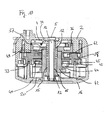
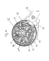
- FIG. 10 shows a sectional view through a portion of the pivot bearing according to the invention 1.
- the first axis 5 is formed by the first means 12 and the third means 15.
- the first means 12 comprises a fixed to the first housing half cover 2 or integrally connected thereto sleeve and a screw with nut or alternatively a riveted joint.
- the third device 15 comprises a sleeve, which is connected to the second housing half cover 16 or integrally connected therewith, and a bearing in which the screw is present.
- Adjacent to the inside 4 of the first housing half cover 2 is the first locking disc 36. It follows the first gear disc 38 and the first trigger gear 40.
- the trigger 42 is adjacent to the inside 20 of the second housing half cover 16 before and encloses a large part of the first axis.
- the first detent disk 36 is mounted so as to be axially displaceable on the first axis 5.
- the first gear wheel 38 and the first trigger gear disc 40 are rotatably mounted on the trigger 42 before.
- the trigger 42 is in turn rotatably mounted on the first axis 5.
- the unlocking teeth 49 of the trigger 42 engage in the corresponding chamfered surfaces of the first decoupling device 37 of the first locking disk.
- the trigger 42 rotates about the first axis 5, whereby the first locking disc 36 is pressed in the direction of the inside 4 of the first housing half cover 2 against the first compression spring 34 with the result that the first bulges 62 of the first locking disc 36 emerge from the corresponding notches or inlets of the first gear disc 38 and the first locking disc 36 and first gear disc 38 can be rotated against each other.
- the first penetrations 45 in the first trigger gear disk 40 through which the first spacers 43 and the first gear disk 38 pass.
- the first attachment points 39 of the first gear wheel 38 engage corresponding fastening means which are connected to the inner side 20 of the second housing half cover 16.
- FIG. 11 shows a schematic plan view of the inside of the second housing half cover 16 with the second receiving part 17, wherein the trigger 42, the first trigger gear 40 and the first gear disc 38 are placed.
- the trigger 42 and the trigger gear disc 40 are rotatably mounted on the second housing half cover 16, which in turn is itself rotatably mounted on the first axis 5 (indicated).
- the first gear wheel 38 is fixedly connected to the second housing half cover 16.
- FIG. 11 Further, one removes the notch or inlets 63 extending radially from the receiving hole to the circumference, into which bulges 62 of the first detent disk 36 corresponding thereto in shape and size can engage (not shown).
- FIG 11 Also shows figure 11 the ring gear segments 118, 120 of the first gear wheel 38 and the first trigger gear disc 40.
- the ring 47 with circumferential unlocking teeth 49 of the trigger 42 interacts with the corresponding corresponding tapered bearing surfaces of the first decoupling device 37 of the first locking disc 36 (not shown).
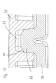
- FIG. 12 shows in a schematic cross-sectional view of a notch or an inlet 63 of the first gear wheel 38 latched or existing bulge 62 of the first locking disc 36.
Landscapes
- Engineering & Computer Science (AREA)
- Chemical & Material Sciences (AREA)
- Combustion & Propulsion (AREA)
- Transportation (AREA)
- Mechanical Engineering (AREA)
- Carriages For Children, Sleds, And Other Hand-Operated Vehicles (AREA)
Priority Applications (1)
| Application Number | Priority Date | Filing Date | Title |
|---|---|---|---|
| EP20100008567 EP2420428B1 (fr) | 2010-08-17 | 2010-08-17 | Pivot et châssis, notamment structure de poussette, comprenant le pivot |
Applications Claiming Priority (1)
| Application Number | Priority Date | Filing Date | Title |
|---|---|---|---|
| EP20100008567 EP2420428B1 (fr) | 2010-08-17 | 2010-08-17 | Pivot et châssis, notamment structure de poussette, comprenant le pivot |
Publications (2)
| Publication Number | Publication Date |
|---|---|
| EP2420428A1 true EP2420428A1 (fr) | 2012-02-22 |
| EP2420428B1 EP2420428B1 (fr) | 2014-02-26 |
Family
ID=43447737
Family Applications (1)
| Application Number | Title | Priority Date | Filing Date |
|---|---|---|---|
| EP20100008567 Not-in-force EP2420428B1 (fr) | 2010-08-17 | 2010-08-17 | Pivot et châssis, notamment structure de poussette, comprenant le pivot |
Country Status (1)
| Country | Link |
|---|---|
| EP (1) | EP2420428B1 (fr) |
Cited By (3)
| Publication number | Priority date | Publication date | Assignee | Title |
|---|---|---|---|---|
| US20150307121A1 (en) * | 2013-06-20 | 2015-10-29 | Unitron Enterprises Zhuhai Co., Ltd. | Stroller |
| CN105815963A (zh) * | 2015-01-06 | 2016-08-03 | 明门香港股份有限公司 | 幼儿餐椅 |
| WO2020232652A1 (fr) * | 2019-05-22 | 2020-11-26 | 深圳市喜德盛自行车股份有限公司 | Structure à grande articulation pour landau |
Citations (8)
| Publication number | Priority date | Publication date | Assignee | Title |
|---|---|---|---|---|
| WO2004052710A1 (fr) * | 2002-12-11 | 2004-06-24 | L'inglesina Baby S.P.A. | Articulation equipee d'elements de transmission traversants |
| US20060071451A1 (en) * | 2004-04-30 | 2006-04-06 | Dynamic Brands, Llc | Folding baby stroller |
| EP1647463A2 (fr) * | 2004-10-15 | 2006-04-19 | Tony Kwan Kwai Wun | Voiture d'enfant |
| DE69926041T2 (de) | 1998-10-14 | 2006-05-04 | Graco Children's Products Inc. | Verriegelungsvorrichtung für zusammenklappbare Kinderwagen |
| EP1762459A2 (fr) | 2005-09-13 | 2007-03-14 | Joh. Georg Hartan | Châssis pour une poussette ou une voiture de poupée ainsi qu'une poussette ou une voiture de poupée |
| DE202008013777U1 (de) | 2008-11-14 | 2009-03-19 | Schiel Gmbh | Gelenk |
| DE202009005043U1 (de) | 2009-03-02 | 2009-09-24 | Schiel Gmbh | Drehgelenk mit Rastgesperre |
| WO2009132985A1 (fr) | 2008-04-28 | 2009-11-05 | Schiel Gmbh | Poussette repliable pour enfants et/ou poupées |
-
2010
- 2010-08-17 EP EP20100008567 patent/EP2420428B1/fr not_active Not-in-force
Patent Citations (8)
| Publication number | Priority date | Publication date | Assignee | Title |
|---|---|---|---|---|
| DE69926041T2 (de) | 1998-10-14 | 2006-05-04 | Graco Children's Products Inc. | Verriegelungsvorrichtung für zusammenklappbare Kinderwagen |
| WO2004052710A1 (fr) * | 2002-12-11 | 2004-06-24 | L'inglesina Baby S.P.A. | Articulation equipee d'elements de transmission traversants |
| US20060071451A1 (en) * | 2004-04-30 | 2006-04-06 | Dynamic Brands, Llc | Folding baby stroller |
| EP1647463A2 (fr) * | 2004-10-15 | 2006-04-19 | Tony Kwan Kwai Wun | Voiture d'enfant |
| EP1762459A2 (fr) | 2005-09-13 | 2007-03-14 | Joh. Georg Hartan | Châssis pour une poussette ou une voiture de poupée ainsi qu'une poussette ou une voiture de poupée |
| WO2009132985A1 (fr) | 2008-04-28 | 2009-11-05 | Schiel Gmbh | Poussette repliable pour enfants et/ou poupées |
| DE202008013777U1 (de) | 2008-11-14 | 2009-03-19 | Schiel Gmbh | Gelenk |
| DE202009005043U1 (de) | 2009-03-02 | 2009-09-24 | Schiel Gmbh | Drehgelenk mit Rastgesperre |
Cited By (4)
| Publication number | Priority date | Publication date | Assignee | Title |
|---|---|---|---|---|
| US20150307121A1 (en) * | 2013-06-20 | 2015-10-29 | Unitron Enterprises Zhuhai Co., Ltd. | Stroller |
| US9701333B2 (en) * | 2013-06-20 | 2017-07-11 | Unitron Enterprises Zhuhai Co., Ltd. | Stroller |
| CN105815963A (zh) * | 2015-01-06 | 2016-08-03 | 明门香港股份有限公司 | 幼儿餐椅 |
| WO2020232652A1 (fr) * | 2019-05-22 | 2020-11-26 | 深圳市喜德盛自行车股份有限公司 | Structure à grande articulation pour landau |
Also Published As
| Publication number | Publication date |
|---|---|
| EP2420428B1 (fr) | 2014-02-26 |
Similar Documents
| Publication | Publication Date | Title |
|---|---|---|
| EP2957479B1 (fr) | Structure de poussette et poussette | |
| EP2326211B1 (fr) | Table avec un plateau de table basculant | |
| EP4098514B1 (fr) | Voiture d'enfant dotée d'un siège enfant pliable | |
| EP2271537B1 (fr) | Poussette repliable pour enfants et/ou poupées | |
| DE10018693A1 (de) | Kindersportwagen | |
| DE102016120455A1 (de) | Kinderwagenvorrichtung | |
| DE10236119A1 (de) | Verstellbares Kabelkompensationsgelenk für einen Sport- oder Kinderwagen | |
| EP2039585A2 (fr) | Véhicule de sport pour enfant | |
| DE102010037506A1 (de) | Buggy | |
| DE102019220580B4 (de) | Zusammenklappbarer autositzwagen | |
| DE102008034985A1 (de) | Standschirm mit einem um seine Achse drehbaren Ausleger | |
| EP3512752B1 (fr) | Cadre de poussette et poussette | |
| EP3147178B1 (fr) | Buggy | |
| EP2420428B1 (fr) | Pivot et châssis, notamment structure de poussette, comprenant le pivot | |
| DE202008013777U1 (de) | Gelenk | |
| EP1762459B1 (fr) | Châssis pour une poussette ou une voiture de poupée ainsi qu'une poussette ou une voiture de poupée | |
| DE202018105304U1 (de) | Kinderwagen | |
| DE29904833U1 (de) | Drehgelenk mit Rastkupplung | |
| EP0849139B1 (fr) | Chariot de golf | |
| DE202009007138U1 (de) | Klappmechanismus für Rollfahrzeug | |
| EP4088985B1 (fr) | Voiture d'enfant ou de poupée | |
| DE102005063362A1 (de) | Zusammenklappbarer Kinderwagen | |
| EP4088988B1 (fr) | Liaison transversale pour une voiture d'enfant ou de poupée | |
| EP1491422B1 (fr) | Poussette ayant un mécanisme de pliage | |
| DE202018101759U1 (de) | Ziehfunktion für einen geklappten Elektroroller |
Legal Events
| Date | Code | Title | Description |
|---|---|---|---|
| 17P | Request for examination filed |
Effective date: 20110318 |
|
| AK | Designated contracting states |
Kind code of ref document: A1 Designated state(s): AL AT BE BG CH CY CZ DE DK EE ES FI FR GB GR HR HU IE IS IT LI LT LU LV MC MK MT NL NO PL PT RO SE SI SK SM TR |
|
| AX | Request for extension of the european patent |
Extension state: BA ME RS |
|
| PUAI | Public reference made under article 153(3) epc to a published international application that has entered the european phase |
Free format text: ORIGINAL CODE: 0009012 |
|
| REG | Reference to a national code |
Ref country code: DE Ref legal event code: R079 Ref document number: 502010006140 Country of ref document: DE Free format text: PREVIOUS MAIN CLASS: B62B0007080000 Ipc: B62B0007060000 |
|
| RIC1 | Information provided on ipc code assigned before grant |
Ipc: B62B 7/08 20060101ALI20121030BHEP Ipc: B62B 7/06 20060101AFI20121030BHEP |
|
| GRAP | Despatch of communication of intention to grant a patent |
Free format text: ORIGINAL CODE: EPIDOSNIGR1 |
|
| INTG | Intention to grant announced |
Effective date: 20130628 |
|
| RAP1 | Party data changed (applicant data changed or rights of an application transferred) |
Owner name: EUROPE BRANDS S.A R.L. |
|
| GRAS | Grant fee paid |
Free format text: ORIGINAL CODE: EPIDOSNIGR3 |
|
| GRAP | Despatch of communication of intention to grant a patent |
Free format text: ORIGINAL CODE: EPIDOSNIGR1 |
|
| INTG | Intention to grant announced |
Effective date: 20131210 |
|
| GRAA | (expected) grant |
Free format text: ORIGINAL CODE: 0009210 |
|
| AK | Designated contracting states |
Kind code of ref document: B1 Designated state(s): AL AT BE BG CH CY CZ DE DK EE ES FI FR GB GR HR HU IE IS IT LI LT LU LV MC MK MT NL NO PL PT RO SE SI SK SM TR |
|
| REG | Reference to a national code |
Ref country code: GB Ref legal event code: FG4D Free format text: NOT ENGLISH |
|
| REG | Reference to a national code |
Ref country code: CH Ref legal event code: EP |
|
| REG | Reference to a national code |
Ref country code: AT Ref legal event code: REF Ref document number: 653415 Country of ref document: AT Kind code of ref document: T Effective date: 20140315 |
|
| REG | Reference to a national code |
Ref country code: DE Ref legal event code: R096 Ref document number: 502010006140 Country of ref document: DE Effective date: 20140403 |
|
| REG | Reference to a national code |
Ref country code: IE Ref legal event code: FG4D Free format text: LANGUAGE OF EP DOCUMENT: GERMAN |
|
| REG | Reference to a national code |
Ref country code: NL Ref legal event code: VDEP Effective date: 20140226 |
|
| REG | Reference to a national code |
Ref country code: LT Ref legal event code: MG4D |
|
| PG25 | Lapsed in a contracting state [announced via postgrant information from national office to epo] |
Ref country code: IS Free format text: LAPSE BECAUSE OF FAILURE TO SUBMIT A TRANSLATION OF THE DESCRIPTION OR TO PAY THE FEE WITHIN THE PRESCRIBED TIME-LIMIT Effective date: 20140626 Ref country code: LT Free format text: LAPSE BECAUSE OF FAILURE TO SUBMIT A TRANSLATION OF THE DESCRIPTION OR TO PAY THE FEE WITHIN THE PRESCRIBED TIME-LIMIT Effective date: 20140226 Ref country code: NO Free format text: LAPSE BECAUSE OF FAILURE TO SUBMIT A TRANSLATION OF THE DESCRIPTION OR TO PAY THE FEE WITHIN THE PRESCRIBED TIME-LIMIT Effective date: 20140526 |
|
| PG25 | Lapsed in a contracting state [announced via postgrant information from national office to epo] |
Ref country code: NL Free format text: LAPSE BECAUSE OF FAILURE TO SUBMIT A TRANSLATION OF THE DESCRIPTION OR TO PAY THE FEE WITHIN THE PRESCRIBED TIME-LIMIT Effective date: 20140226 Ref country code: FI Free format text: LAPSE BECAUSE OF FAILURE TO SUBMIT A TRANSLATION OF THE DESCRIPTION OR TO PAY THE FEE WITHIN THE PRESCRIBED TIME-LIMIT Effective date: 20140226 Ref country code: CY Free format text: LAPSE BECAUSE OF FAILURE TO SUBMIT A TRANSLATION OF THE DESCRIPTION OR TO PAY THE FEE WITHIN THE PRESCRIBED TIME-LIMIT Effective date: 20140226 Ref country code: PT Free format text: LAPSE BECAUSE OF FAILURE TO SUBMIT A TRANSLATION OF THE DESCRIPTION OR TO PAY THE FEE WITHIN THE PRESCRIBED TIME-LIMIT Effective date: 20140626 Ref country code: SE Free format text: LAPSE BECAUSE OF FAILURE TO SUBMIT A TRANSLATION OF THE DESCRIPTION OR TO PAY THE FEE WITHIN THE PRESCRIBED TIME-LIMIT Effective date: 20140226 |
|
| PG25 | Lapsed in a contracting state [announced via postgrant information from national office to epo] |
Ref country code: HR Free format text: LAPSE BECAUSE OF FAILURE TO SUBMIT A TRANSLATION OF THE DESCRIPTION OR TO PAY THE FEE WITHIN THE PRESCRIBED TIME-LIMIT Effective date: 20140226 Ref country code: LV Free format text: LAPSE BECAUSE OF FAILURE TO SUBMIT A TRANSLATION OF THE DESCRIPTION OR TO PAY THE FEE WITHIN THE PRESCRIBED TIME-LIMIT Effective date: 20140226 |
|
| PG25 | Lapsed in a contracting state [announced via postgrant information from national office to epo] |
Ref country code: CZ Free format text: LAPSE BECAUSE OF FAILURE TO SUBMIT A TRANSLATION OF THE DESCRIPTION OR TO PAY THE FEE WITHIN THE PRESCRIBED TIME-LIMIT Effective date: 20140226 Ref country code: RO Free format text: LAPSE BECAUSE OF FAILURE TO SUBMIT A TRANSLATION OF THE DESCRIPTION OR TO PAY THE FEE WITHIN THE PRESCRIBED TIME-LIMIT Effective date: 20140226 Ref country code: DK Free format text: LAPSE BECAUSE OF FAILURE TO SUBMIT A TRANSLATION OF THE DESCRIPTION OR TO PAY THE FEE WITHIN THE PRESCRIBED TIME-LIMIT Effective date: 20140226 Ref country code: EE Free format text: LAPSE BECAUSE OF FAILURE TO SUBMIT A TRANSLATION OF THE DESCRIPTION OR TO PAY THE FEE WITHIN THE PRESCRIBED TIME-LIMIT Effective date: 20140226 |
|
| PGFP | Annual fee paid to national office [announced via postgrant information from national office to epo] |
Ref country code: DE Payment date: 20140827 Year of fee payment: 5 |
|
| REG | Reference to a national code |
Ref country code: DE Ref legal event code: R097 Ref document number: 502010006140 Country of ref document: DE |
|
| PG25 | Lapsed in a contracting state [announced via postgrant information from national office to epo] |
Ref country code: ES Free format text: LAPSE BECAUSE OF FAILURE TO SUBMIT A TRANSLATION OF THE DESCRIPTION OR TO PAY THE FEE WITHIN THE PRESCRIBED TIME-LIMIT Effective date: 20140226 Ref country code: SK Free format text: LAPSE BECAUSE OF FAILURE TO SUBMIT A TRANSLATION OF THE DESCRIPTION OR TO PAY THE FEE WITHIN THE PRESCRIBED TIME-LIMIT Effective date: 20140226 Ref country code: PL Free format text: LAPSE BECAUSE OF FAILURE TO SUBMIT A TRANSLATION OF THE DESCRIPTION OR TO PAY THE FEE WITHIN THE PRESCRIBED TIME-LIMIT Effective date: 20140226 |
|
| PGFP | Annual fee paid to national office [announced via postgrant information from national office to epo] |
Ref country code: GB Payment date: 20140827 Year of fee payment: 5 |
|
| PLBE | No opposition filed within time limit |
Free format text: ORIGINAL CODE: 0009261 |
|
| STAA | Information on the status of an ep patent application or granted ep patent |
Free format text: STATUS: NO OPPOSITION FILED WITHIN TIME LIMIT |
|
| 26N | No opposition filed |
Effective date: 20141127 |
|
| REG | Reference to a national code |
Ref country code: DE Ref legal event code: R097 Ref document number: 502010006140 Country of ref document: DE Effective date: 20141127 |
|
| PG25 | Lapsed in a contracting state [announced via postgrant information from national office to epo] |
Ref country code: LU Free format text: LAPSE BECAUSE OF FAILURE TO SUBMIT A TRANSLATION OF THE DESCRIPTION OR TO PAY THE FEE WITHIN THE PRESCRIBED TIME-LIMIT Effective date: 20140817 Ref country code: MC Free format text: LAPSE BECAUSE OF FAILURE TO SUBMIT A TRANSLATION OF THE DESCRIPTION OR TO PAY THE FEE WITHIN THE PRESCRIBED TIME-LIMIT Effective date: 20140226 Ref country code: IT Free format text: LAPSE BECAUSE OF FAILURE TO SUBMIT A TRANSLATION OF THE DESCRIPTION OR TO PAY THE FEE WITHIN THE PRESCRIBED TIME-LIMIT Effective date: 20140226 |
|
| REG | Reference to a national code |
Ref country code: CH Ref legal event code: PL |
|
| PG25 | Lapsed in a contracting state [announced via postgrant information from national office to epo] |
Ref country code: CH Free format text: LAPSE BECAUSE OF NON-PAYMENT OF DUE FEES Effective date: 20140831 Ref country code: LI Free format text: LAPSE BECAUSE OF NON-PAYMENT OF DUE FEES Effective date: 20140831 Ref country code: BE Free format text: LAPSE BECAUSE OF NON-PAYMENT OF DUE FEES Effective date: 20140831 |
|
| REG | Reference to a national code |
Ref country code: IE Ref legal event code: MM4A |
|
| PG25 | Lapsed in a contracting state [announced via postgrant information from national office to epo] |
Ref country code: SI Free format text: LAPSE BECAUSE OF FAILURE TO SUBMIT A TRANSLATION OF THE DESCRIPTION OR TO PAY THE FEE WITHIN THE PRESCRIBED TIME-LIMIT Effective date: 20140226 |
|
| REG | Reference to a national code |
Ref country code: FR Ref legal event code: ST Effective date: 20150430 |
|
| PG25 | Lapsed in a contracting state [announced via postgrant information from national office to epo] |
Ref country code: FR Free format text: LAPSE BECAUSE OF NON-PAYMENT OF DUE FEES Effective date: 20140901 Ref country code: IE Free format text: LAPSE BECAUSE OF NON-PAYMENT OF DUE FEES Effective date: 20140817 |
|
| REG | Reference to a national code |
Ref country code: DE Ref legal event code: R119 Ref document number: 502010006140 Country of ref document: DE |
|
| GBPC | Gb: european patent ceased through non-payment of renewal fee |
Effective date: 20150817 |
|
| PG25 | Lapsed in a contracting state [announced via postgrant information from national office to epo] |
Ref country code: SM Free format text: LAPSE BECAUSE OF FAILURE TO SUBMIT A TRANSLATION OF THE DESCRIPTION OR TO PAY THE FEE WITHIN THE PRESCRIBED TIME-LIMIT Effective date: 20140226 |
|
| PG25 | Lapsed in a contracting state [announced via postgrant information from national office to epo] |
Ref country code: MT Free format text: LAPSE BECAUSE OF FAILURE TO SUBMIT A TRANSLATION OF THE DESCRIPTION OR TO PAY THE FEE WITHIN THE PRESCRIBED TIME-LIMIT Effective date: 20140226 Ref country code: BG Free format text: LAPSE BECAUSE OF FAILURE TO SUBMIT A TRANSLATION OF THE DESCRIPTION OR TO PAY THE FEE WITHIN THE PRESCRIBED TIME-LIMIT Effective date: 20140226 Ref country code: GR Free format text: LAPSE BECAUSE OF FAILURE TO SUBMIT A TRANSLATION OF THE DESCRIPTION OR TO PAY THE FEE WITHIN THE PRESCRIBED TIME-LIMIT Effective date: 20140527 |
|
| PG25 | Lapsed in a contracting state [announced via postgrant information from national office to epo] |
Ref country code: DE Free format text: LAPSE BECAUSE OF NON-PAYMENT OF DUE FEES Effective date: 20160301 Ref country code: HU Free format text: LAPSE BECAUSE OF FAILURE TO SUBMIT A TRANSLATION OF THE DESCRIPTION OR TO PAY THE FEE WITHIN THE PRESCRIBED TIME-LIMIT; INVALID AB INITIO Effective date: 20100817 Ref country code: GB Free format text: LAPSE BECAUSE OF NON-PAYMENT OF DUE FEES Effective date: 20150817 Ref country code: TR Free format text: LAPSE BECAUSE OF FAILURE TO SUBMIT A TRANSLATION OF THE DESCRIPTION OR TO PAY THE FEE WITHIN THE PRESCRIBED TIME-LIMIT Effective date: 20140226 |
|
| REG | Reference to a national code |
Ref country code: AT Ref legal event code: MM01 Ref document number: 653415 Country of ref document: AT Kind code of ref document: T Effective date: 20150817 |
|
| PG25 | Lapsed in a contracting state [announced via postgrant information from national office to epo] |
Ref country code: AT Free format text: LAPSE BECAUSE OF NON-PAYMENT OF DUE FEES Effective date: 20150817 |
|
| PG25 | Lapsed in a contracting state [announced via postgrant information from national office to epo] |
Ref country code: MK Free format text: LAPSE BECAUSE OF FAILURE TO SUBMIT A TRANSLATION OF THE DESCRIPTION OR TO PAY THE FEE WITHIN THE PRESCRIBED TIME-LIMIT Effective date: 20140226 |
|
| PG25 | Lapsed in a contracting state [announced via postgrant information from national office to epo] |
Ref country code: AL Free format text: LAPSE BECAUSE OF FAILURE TO SUBMIT A TRANSLATION OF THE DESCRIPTION OR TO PAY THE FEE WITHIN THE PRESCRIBED TIME-LIMIT Effective date: 20140226 |