EP3147178B1 - Buggy - Google Patents
Buggy Download PDFInfo
- Publication number
- EP3147178B1 EP3147178B1 EP16187863.2A EP16187863A EP3147178B1 EP 3147178 B1 EP3147178 B1 EP 3147178B1 EP 16187863 A EP16187863 A EP 16187863A EP 3147178 B1 EP3147178 B1 EP 3147178B1
- Authority
- EP
- European Patent Office
- Prior art keywords
- sliding frame
- strut
- buggy
- hinge
- upper sliding
- Prior art date
- Legal status (The legal status is an assumption and is not a legal conclusion. Google has not performed a legal analysis and makes no representation as to the accuracy of the status listed.)
- Active
Links
Images



Classifications
-
- B—PERFORMING OPERATIONS; TRANSPORTING
- B62—LAND VEHICLES FOR TRAVELLING OTHERWISE THAN ON RAILS
- B62B—HAND-PROPELLED VEHICLES, e.g. HAND CARTS OR PERAMBULATORS; SLEDGES
- B62B7/00—Carriages for children; Perambulators, e.g. dolls' perambulators
- B62B7/04—Carriages for children; Perambulators, e.g. dolls' perambulators having more than one wheel axis; Steering devices therefor
- B62B7/06—Carriages for children; Perambulators, e.g. dolls' perambulators having more than one wheel axis; Steering devices therefor collapsible or foldable
- B62B7/062—Coupling unit between front wheels, rear wheels and handle
-
- B—PERFORMING OPERATIONS; TRANSPORTING
- B62—LAND VEHICLES FOR TRAVELLING OTHERWISE THAN ON RAILS
- B62B—HAND-PROPELLED VEHICLES, e.g. HAND CARTS OR PERAMBULATORS; SLEDGES
- B62B7/00—Carriages for children; Perambulators, e.g. dolls' perambulators
- B62B7/04—Carriages for children; Perambulators, e.g. dolls' perambulators having more than one wheel axis; Steering devices therefor
- B62B7/06—Carriages for children; Perambulators, e.g. dolls' perambulators having more than one wheel axis; Steering devices therefor collapsible or foldable
- B62B7/08—Carriages for children; Perambulators, e.g. dolls' perambulators having more than one wheel axis; Steering devices therefor collapsible or foldable in the direction of, or at right angles to, the wheel axis
-
- B—PERFORMING OPERATIONS; TRANSPORTING
- B62—LAND VEHICLES FOR TRAVELLING OTHERWISE THAN ON RAILS
- B62B—HAND-PROPELLED VEHICLES, e.g. HAND CARTS OR PERAMBULATORS; SLEDGES
- B62B2205/00—Hand-propelled vehicles or sledges being foldable or dismountable when not in use
- B62B2205/18—Geared articulations
-
- B—PERFORMING OPERATIONS; TRANSPORTING
- B62—LAND VEHICLES FOR TRAVELLING OTHERWISE THAN ON RAILS
- B62B—HAND-PROPELLED VEHICLES, e.g. HAND CARTS OR PERAMBULATORS; SLEDGES
- B62B2205/00—Hand-propelled vehicles or sledges being foldable or dismountable when not in use
- B62B2205/20—Catches; Locking or releasing an articulation
-
- B—PERFORMING OPERATIONS; TRANSPORTING
- B62—LAND VEHICLES FOR TRAVELLING OTHERWISE THAN ON RAILS
- B62B—HAND-PROPELLED VEHICLES, e.g. HAND CARTS OR PERAMBULATORS; SLEDGES
- B62B2205/00—Hand-propelled vehicles or sledges being foldable or dismountable when not in use
- B62B2205/20—Catches; Locking or releasing an articulation
- B62B2205/22—Catches; Locking or releasing an articulation remotely controlled, e.g. from the handlebar
Definitions
- the present invention relates to a buggy or pram comprising an upper sliding frame, a lower sliding frame to which the front wheels are attached, the upper sliding frame and lower sliding frame being approximately aligned with one another when viewed from the side in the erected driving position of the buggy, and a rear frame which the rear wheels are attached, which in the driving position seen in the side view is aligned at an angle to the sliding frame, the buggy can be folded from the driving position around joints into a transport position, in the upper sliding frame, lower sliding frame and rear frame comparatively flat on each other lie.
- Buggy or prams of the aforementioned type are known in principle from the prior art.
- WO 2005012738 A1 such a buggy is described, whereby in Figure 1 whose chassis is shown.
- the three parts of the chassis namely the upper sliding frame, the lower sliding frame and the rear frame, pivot about a single joint axis which extends in the transverse direction of the chassis. This presupposes that the approximately disk-shaped joint parts connected to the individual frame parts of the chassis are arranged one behind the other as seen in the direction of the joint axis.
- the object of the present invention is to provide a buggy or stroller with the features of the type mentioned at the beginning, which provides for a movement of the upper sliding frame in the direction of the lower sliding frame of the chassis when folded, but the construction in the articulated area is chosen in this way is that injuries to the user when folding are avoided.
- the solution to this problem is provided by a buggy or stroller of the type mentioned at the outset with the characterizing features of the main claim.
- articulation units are provided, on which the end of a strut of the upper sliding frame facing this end on the one hand and the end of a strut of the rear frame facing in each case on the other hand are pivotably mounted about mutually parallel joint axes
- the solution according to the invention makes it possible to avoid injuries in a construction in which, when folded, the struts of the upper sliding frame move in the direction of the struts of the lower sliding frame.
- a hinge cover is provided on the hinge units which, when the stroller is folded into the transport position, prevents a body part of the user from being caught between the struts to be moved toward one another in the space between them, since the respective struts Ends of the struts in the vicinity of the joint are spaced apart on the user side
- the end of the strut of the upper sliding frame facing the joint unit and the end of the strut of the rear frame facing the joint unit are connected to one another via gear means in the area of the joint unit such that when the strut of the upper sliding frame is pivoted in a first direction of rotation results in a pivoting movement of the strut of the rear frame in the opposite direction of rotation.
- the user pivots the strut of the upper sliding frame after a lock has been released, as a result of which the strut of the rear frame also pivots and the chassis of the buggy is folded flat in one movement into the transport position.
- the end of the strut of the lower sliding frame facing the articulated unit is fixedly attached to the articulated unit, so that when folding the struts of the lower sliding frame, on which the front wheels are located, pivot with the articulated units.
- At least one first gearwheel which rotates about the hinge axis of the strut of the upper sliding frame
- at least one second gearwheel which rotates about the axis of the strut of the rear frame parallel to it
- Both gears mesh with one another and, when the upper sliding frame is pivoted, cause the rear frame on which the rear wheels are located to pivot towards the lower sliding frame.
- at least one component in particular a hook, is preferably provided which, after loosening an engagement with locking elements, enables the joint units to be unlocked and thus the struts to be pivoted and the buggy to be folded into the flat transport position. This construction enables easy handling and quick folding of the stroller with just a few handles.
- the hook can be brought out of engagement with the locking elements by means of at least one tension element against a spring force, so that after the release of the tension element the hook moves back into the engagement position.
- locking elements pins or the like on gear units which cooperate with pawls and / or ring grooves as stop elements on at least one base plate of the articulation unit. This can be used to effect the fixing in the upright driving position and possibly by other means Locking elements also limit the swivel path in the flat transport position and lock the articulated units also in this position.
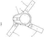
- the buggy chassis includes one Upper sliding frame, which in principle is approximately U-shaped when viewed from the front, with an upper transverse connection which cannot be seen here and furthermore has a downwardly extending strut 11 on both sides, which extends as far as the joint unit 12.
- the chassis of the stroller continues in the lower sliding frame, the strut 13 of which runs approximately in alignment with the strut 11 of the upper sliding frame, it being possible for this strut 13 to be firmly connected to the articulation unit 12.
- Such parallel struts are in turn present on both sides of the stroller.
- the front wheels 14 are mounted at the lower end of the struts 13 of the lower sliding frame.
- the struts 11 of the upper sliding frame are articulated to the joint unit 12, specifically about a horizontal axis which extends in the transverse direction of the stroller.
- struts 15 of the rear frame are each articulated at their upper end to the joint unit 12.
- the rear wheels 16 of the stroller are mounted.
- the struts 15 of the rear frame extend in the in Figure 1 shown driving position each at an angle to the struts 11 of the upper sliding frame and to the struts 13 of the lower sliding frame.
- the struts of the frame units of the chassis are connected to one another in the articulated unit 12 via gear means such that when the strut 11 is pivoted when the strut 11 of the upper slide hammer is pivoted, there is an inevitable coupling with the pivoting movement of the strut 15 of the rear frame and the latter thus relates to the
- the strut 13 of the lower sliding frame moves until the folded transport position is reached, in which the struts 11, 13, 15 are almost parallel to one another, so that the transport position is very flat.
- Figure 2 shows a schematic enlarged side view of the joint unit 12, in which the strut 11 of the upper sliding frame extending from it, the strut 15 of the rear frame extending from this and the strut 13 of the lower sliding frame extending from the joint unit recognizes.
- the joint unit has a joint cover 121, so that when the stroller is folded into the transport position, there is no risk that the user will get his fingers caught in the space between the struts 11 and 13 or 15 and 13 to be moved towards one another. It can be seen that the joint unit 12 prevents this since the respective ends of the struts in the vicinity of the joint are spaced apart from one another on the user side.
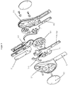
- Figure 3 shows an exploded view of a joint unit 12. It can be seen here that the strut 13 of the lower sliding frame, which leads to the front wheel, is arranged approximately radially / tangentially to the joint axis and is firmly connected to the joint cover 121.
- the joint unit has a cover 122 on the visible side. When viewed in the direction of the joint axis, there is a hook 123 behind the joint cover 121 by means of which the joint can be unlocked when the buggy is to be folded up. Unlocking can be done by pulling the hook 123.
- a tension element 127 is provided, the function of which will be explained in more detail below.
- a gear part is connected to the strut 15 of the rear frame with a first larger gear 124, which rotates about the main axis of the joint. Furthermore, a second gear part 125 is provided with a smaller gear, which meshes with the first gear 124 and which consequently rotates in the opposite direction of rotation as the first larger gear, so that it is achieved that during the pivoting movement of the strut 11 of the upper sliding frame the the gear part 124 connected strut 15 of the rear frame pivots in the opposite direction and moves with it. Furthermore, the joint unit comprises a smaller base plate 129, arranged between the joint cover 121 and the gear part 124, and a larger second base plate 130, which is arranged in front of the second joint cover 126.
- the hook 123 is connected to a spring 128 and engages in a recess 131 in the smaller base plate 129. Furthermore, a first locking pin 132 and a second locking pin 133 are provided, each of which overlaps bent ends of the hook 123, the first locking pin 132 being located on the first gear unit 124 (see Figure 3 ) and engages in a pawl on the small base plate 129, while the second locking pin 133 is located on the second gear unit 125 and engages in a pawl on the second larger base plate 130. In this way, both gears can be locked via the locking pins 132, 133 by means of the hook 123, and thus the pivoting of all struts 11, 13 and 15 can be prevented.
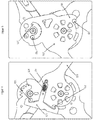
- Figure 5 shows that secondary locking pins 134 (on the gear unit 124) or 135 (on the smaller gear unit 125) can be located on the other side of the gear units, wherein the locking pin 134 engages under a pawl 136 of the large base plate 130 and the locking pin 135 engages in an annular groove 137 of the large base plate 130.
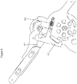
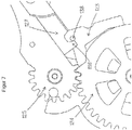
- the pulling element 127 can be used to pull the hook 123 out against the force of the spring 128 in the direction of the arrow in order to release the engagement with the various locking pins. How from Figure 7 recognizable, the pulling element 127 engages with a lug 139 behind a pin 138 on the hook 123. After the hook 123 has been pulled out, the base plates 129 and 130 of the joint can rotate freely. The spring 128 pulls the hook 123 back into the locked position after passing the locking pins 132, 133 (see Figure 8 .) Figure 9 shows the engagement of the two gears 124, 125, which represent the transmission means of the joint unit.
- Figure 10 shows again the engagement of the locking pin 133 on the small base plate 129 in the folded transport position of the buggy, whereby the pivoting movement of the strut 11 of the upper sliding frame is limited (see also Figure 8 with the arrow drawn there for the swivel direction.)
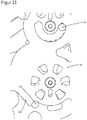
- Figure 11 one can see the engagement of the secondary locking pins 134, 135 in the annular groove 137 or on a further pawl 140 of the large base plate 130, whereby by comparison with the illustration according to FIG Figure 5 can recognize the pivoting path of the locking pins 134, 135 relative to the base plate 130.
Landscapes
- Engineering & Computer Science (AREA)
- Chemical & Material Sciences (AREA)
- Combustion & Propulsion (AREA)
- Transportation (AREA)
- Mechanical Engineering (AREA)
- Carriages For Children, Sleds, And Other Hand-Operated Vehicles (AREA)
- Handcart (AREA)
Claims (4)
- Landau ou poussette comprenant un châssis coulissant supérieur, un châssis coulissant inférieur, au niveau duquel les roues avant sont montées, dans lequel le châssis coulissant supérieur et le châssis coulissant inférieur, dans la position dépliée du landau en vue depuis le côté, sont approximativement alignés l'un avec l'autre, ainsi qu'un châssis arrière au niveau duquel les roues arrières sont montées lequel, dans la position de déplacement en vue depuis le côté, est respectivement orienté selon un angle par rapport aux châssis coulissants, dans lequel le landau est repliable autour d'articulations de la position de déplacement à une position de transport dans laquelle le châssis coulissant supérieur, le châssis coulissant inférieur et le châssis arrière reposent comparativement à plat les uns sur les autres, dans lequel des unités d'articulation sont prévues (12) au niveau desquelles l'extrémité, respectivement tournée vers celles-ci, d'une entretoise (11) du châssis coulissant supérieur d'une part et l'extrémité, respectivement tournée vers celles-ci, d'une entretoise du châssis arrière (15) d'autre part sont montées de façon pivotante autour d'axes d'articulation parallèles entre eux, dans lequel l'extrémité tournée vers l'unité d'articulation (12) de l'entretoise (11) du châssis coulissant supérieur et l'extrémité tournée vers l'unité d'articulation de l'entretoise (15) du châssis arrière sont reliées entre elles via des moyens moteurs (124, 125) dans la zone de l'unité d'articulation de telle sorte qu'en cas de mouvement pivotant de l'entretoise (11) du châssis coulissant supérieur dans un premier sens de rotation, il en résulte un mouvement de rotation de l'entretoise (15) du châssis arrière dans le sens de rotation contraire, dans lequel on prévoit, en guise de moyens moteurs, au moins une roue dentée (125) qui tourne autour de l'axe d'articulation de l'entretoise (11) du châssis coulissant supérieur ainsi qu'au moins une deuxième roue dentée (124) qui tourne autour de l'axe qui lui est parallèle de l'entretoise (13) du châssis arrière, caractérisé en ce qu'au moins un élément, en particulier un crochet (123) est prévu lequel, après la mise hors d'une prise d'avec des éléments de verrouillage (132, 133), permet un déverrouillage des unités d'articulation et ainsi un pivotement des entretoises (11, 13, 15) et un repliage du landau dans la position de transport plate et qu'en guise d'éléments de verrouillage (132, 133), on prévoit des goupilles ou similaires au niveau d'unités de roue dentée (124, 125) qui coopèrent avec des cliquets (136) et/ou rainures annulaires (137) en tant qu'éléments de butée sur au moins une plaque de base (130) de l'unité d'articulation.
- Landau selon la revendication 1, caractérisé en ce que l'extrémité tournée vers l'unité d'articulation (12) de l'entretoise (13) du châssis coulissant inférieur est montée de manière fixe sur l'unité d'articulation (12).
- Landau selon l'une des revendications 1 ou 2, caractérisé en ce que l'on prévoit un recouvrement d'articulation (121) au niveau des unités d'articulation (12) lequel, lors du repliage du landau dans la position de transport, empêche un coincement d'une partie du corps de l'utilisateur entre les entretoises (11 et 13) ou (15 et 13) se déplaçant l'une vers l'autre dans l'espace intermédiaire de celles-ci étant donné que les extrémités respectives des entretoises sont espacées entre elles côté utilisateur à proximité de l'articulation.
- Landau selon la revendication 1, caractérisé en ce que le crochet (123) peut être amené hors de prise d'avec les éléments de verrouillage (132, 133) à l'encontre d'une force élastique au moyen d'au moins un élément de traction (127).
Applications Claiming Priority (1)
| Application Number | Priority Date | Filing Date | Title |
|---|---|---|---|
| DE102015115396.3A DE102015115396A1 (de) | 2015-09-11 | 2015-09-11 | Buggy |
Publications (2)
| Publication Number | Publication Date |
|---|---|
| EP3147178A1 EP3147178A1 (fr) | 2017-03-29 |
| EP3147178B1 true EP3147178B1 (fr) | 2020-02-26 |
Family
ID=56893817
Family Applications (1)
| Application Number | Title | Priority Date | Filing Date |
|---|---|---|---|
| EP16187863.2A Active EP3147178B1 (fr) | 2015-09-11 | 2016-09-08 | Buggy |
Country Status (3)
| Country | Link |
|---|---|
| US (1) | US10059359B2 (fr) |
| EP (1) | EP3147178B1 (fr) |
| DE (1) | DE102015115396A1 (fr) |
Families Citing this family (6)
| Publication number | Priority date | Publication date | Assignee | Title |
|---|---|---|---|---|
| JP2018526278A (ja) * | 2015-09-02 | 2018-09-13 | ラークテイル ピー・ティー・ワイ リミテッド | 折り畳み式ベビーカー |
| CN107792153B (zh) * | 2016-09-06 | 2020-05-12 | 明门香港股份有限公司 | 车架收折结构 |
| CN110051511A (zh) * | 2018-12-27 | 2019-07-26 | 航天中心医院 | 具有腋托的助行器 |
| CN115817614A (zh) * | 2019-07-15 | 2023-03-21 | 明门瑞士股份有限公司 | 杆件收合锁定机构及婴儿车架 |
| CN121990032A (zh) * | 2021-08-10 | 2026-05-08 | 明门(中国)幼童用品有限公司 | 可收折的行动载具 |
| CN115723831A (zh) * | 2021-09-01 | 2023-03-03 | 明门(中国)幼童用品有限公司 | 连动收折机构及儿童载具 |
Family Cites Families (19)
| Publication number | Priority date | Publication date | Assignee | Title |
|---|---|---|---|---|
| CA1202995A (fr) * | 1982-03-31 | 1986-04-08 | Abdelraouf M.S. Al-Sheikh | Poussette pliante |
| US6095548A (en) * | 1997-07-28 | 2000-08-01 | Racing Strollers, Inc. | Baby stroller |
| DE60305311D1 (de) | 2003-07-31 | 2006-06-22 | All Our Kids Europ B V | Verschlusssystem und Kinderwagen mit einem solchen System |
| PL1744941T3 (pl) * | 2004-04-30 | 2015-08-31 | Babyjogger Llc | Składany dziecięcy wózek spacerowy |
| NL1033729C2 (nl) * | 2007-04-20 | 2008-10-21 | Maxi Miliaan Bv | Wandelwagen. |
| DE102007045068B3 (de) * | 2007-09-19 | 2009-04-02 | Otto Bock Healthcare Ip Gmbh & Co. Kg | Kinder-Sportkarre |
| CA2752540C (fr) * | 2009-02-12 | 2017-06-13 | Clek Inc. | Poussette pliante |
| US8226110B2 (en) * | 2009-10-08 | 2012-07-24 | Unique Product & Design Co., Ltd. | Foldable joint for baby stroller |
| US8714581B2 (en) * | 2010-01-25 | 2014-05-06 | Cosco Management, Inc. | Compact foldable stroller |
| NL2004371C2 (en) * | 2010-03-09 | 2011-09-13 | Maxi Miliaan Bv | A STROLLER. |
| CN201800747U (zh) * | 2010-08-03 | 2011-04-20 | 明门香港股份有限公司 | 可收合婴儿车 |
| US8517412B2 (en) * | 2011-09-22 | 2013-08-27 | Baby Trend Inc. | Foldable stroller frame having three sections joined to and foldable around a common hub structure |
| US20130113185A1 (en) * | 2011-11-07 | 2013-05-09 | Dynamic Brands, Llc | Baby stroller |
| US8596669B2 (en) * | 2011-11-07 | 2013-12-03 | Unique Product & Design Co., Ltd. | Baby stroller |
| CN103318242B (zh) * | 2012-03-19 | 2015-11-25 | 珠海优力创工贸有限公司 | 具有换向座位的可收合婴儿车 |
| US9199658B2 (en) * | 2012-06-22 | 2015-12-01 | Khai Gan Chuah | Baby stroller folding mechanism |
| US8870213B1 (en) * | 2013-05-20 | 2014-10-28 | Dongguang Master Kids Toy Co., Ltd. | Single-hand foldable baby stroller |
| US8985616B1 (en) * | 2014-06-24 | 2015-03-24 | Yong Xiang Chen | Baby stroller capable of being folded with one hand |
| US8998241B1 (en) * | 2014-09-15 | 2015-04-07 | Pao-Hsien Cheng | Foldable structure for baby stroller |
-
2015
- 2015-09-11 DE DE102015115396.3A patent/DE102015115396A1/de not_active Withdrawn
-
2016
- 2016-01-19 US US15/000,058 patent/US10059359B2/en active Active
- 2016-09-08 EP EP16187863.2A patent/EP3147178B1/fr active Active
Non-Patent Citations (1)
| Title |
|---|
| None * |
Also Published As
| Publication number | Publication date |
|---|---|
| DE102015115396A1 (de) | 2017-03-16 |
| US20170072981A1 (en) | 2017-03-16 |
| EP3147178A1 (fr) | 2017-03-29 |
| US10059359B2 (en) | 2018-08-28 |
Similar Documents
| Publication | Publication Date | Title |
|---|---|---|
| DE2822944C2 (de) | Zusammenklappbarer Wagen zur Beförderung von Kleinkindern | |
| DE2823086C2 (de) | Kinderwagen mit einer für beide Fahrtrichtungen umstellbaren Schiebevorrichtung | |
| EP3261901B1 (fr) | Siege d'enfant pliable et poussette comprenant un tel siege | |
| DE69504325T2 (de) | Kinderwagen | |
| EP3147178A1 (fr) | Buggy | |
| DE102016120455A1 (de) | Kinderwagenvorrichtung | |
| DE102017109236A1 (de) | Kinderwagenvorrichtung | |
| DE102013103326B4 (de) | Kindersitzvorrichtung und deren Verwendung | |
| DE1775524A1 (de) | Selbsttaetig verriegelbares Gelenk | |
| DE10018693A1 (de) | Kindersportwagen | |
| WO2019076831A1 (fr) | Siège de poussette et système de poussette | |
| EP3512752B1 (fr) | Cadre de poussette et poussette | |
| DE102020124948A1 (de) | Kinderwagenvorrichtung | |
| EP3626578A1 (fr) | Cadre | |
| EP3509928B1 (fr) | Poussette | |
| DE102016208696A1 (de) | Faltmechanismus für Autositzadapter und Kinderwagen, der denselben aufweist | |
| WO2013149641A1 (fr) | Articulation multifonction | |
| DE102011103203A1 (de) | Klapprad | |
| EP2077199B1 (fr) | Dispositif pare-vent doté d'un joint double synchronisé | |
| EP2420428A1 (fr) | Pivot et châssis, notamment structure de poussette, comprenant le pivot | |
| WO2017190173A1 (fr) | Articulation | |
| EP4088985B1 (fr) | Voiture d'enfant ou de poupée | |
| DE102016200437B4 (de) | Kinderwagen | |
| DE202019105127U1 (de) | Kinderwagen | |
| EP1491422B1 (fr) | Poussette ayant un mécanisme de pliage |
Legal Events
| Date | Code | Title | Description |
|---|---|---|---|
| PUAI | Public reference made under article 153(3) epc to a published international application that has entered the european phase |
Free format text: ORIGINAL CODE: 0009012 |
|
| STAA | Information on the status of an ep patent application or granted ep patent |
Free format text: STATUS: THE APPLICATION HAS BEEN PUBLISHED |
|
| AK | Designated contracting states |
Kind code of ref document: A1 Designated state(s): AL AT BE BG CH CY CZ DE DK EE ES FI FR GB GR HR HU IE IS IT LI LT LU LV MC MK MT NL NO PL PT RO RS SE SI SK SM TR |
|
| AX | Request for extension of the european patent |
Extension state: BA ME |
|
| STAA | Information on the status of an ep patent application or granted ep patent |
Free format text: STATUS: REQUEST FOR EXAMINATION WAS MADE |
|
| 17P | Request for examination filed |
Effective date: 20170929 |
|
| GRAP | Despatch of communication of intention to grant a patent |
Free format text: ORIGINAL CODE: EPIDOSNIGR1 |
|
| STAA | Information on the status of an ep patent application or granted ep patent |
Free format text: STATUS: GRANT OF PATENT IS INTENDED |
|
| INTG | Intention to grant announced |
Effective date: 20190925 |
|
| GRAS | Grant fee paid |
Free format text: ORIGINAL CODE: EPIDOSNIGR3 |
|
| GRAA | (expected) grant |
Free format text: ORIGINAL CODE: 0009210 |
|
| STAA | Information on the status of an ep patent application or granted ep patent |
Free format text: STATUS: THE PATENT HAS BEEN GRANTED |
|
| AK | Designated contracting states |
Kind code of ref document: B1 Designated state(s): AL AT BE BG CH CY CZ DE DK EE ES FI FR GB GR HR HU IE IS IT LI LT LU LV MC MK MT NL NO PL PT RO RS SE SI SK SM TR |
|
| REG | Reference to a national code |
Ref country code: GB Ref legal event code: FG4D Free format text: NOT ENGLISH |
|
| REG | Reference to a national code |
Ref country code: CH Ref legal event code: EP |
|
| REG | Reference to a national code |
Ref country code: AT Ref legal event code: REF Ref document number: 1237280 Country of ref document: AT Kind code of ref document: T Effective date: 20200315 |
|
| REG | Reference to a national code |
Ref country code: IE Ref legal event code: FG4D Free format text: LANGUAGE OF EP DOCUMENT: GERMAN |
|
| REG | Reference to a national code |
Ref country code: DE Ref legal event code: R096 Ref document number: 502016008899 Country of ref document: DE |
|
| PG25 | Lapsed in a contracting state [announced via postgrant information from national office to epo] |
Ref country code: RS Free format text: LAPSE BECAUSE OF FAILURE TO SUBMIT A TRANSLATION OF THE DESCRIPTION OR TO PAY THE FEE WITHIN THE PRESCRIBED TIME-LIMIT Effective date: 20200226 Ref country code: NO Free format text: LAPSE BECAUSE OF FAILURE TO SUBMIT A TRANSLATION OF THE DESCRIPTION OR TO PAY THE FEE WITHIN THE PRESCRIBED TIME-LIMIT Effective date: 20200526 Ref country code: FI Free format text: LAPSE BECAUSE OF FAILURE TO SUBMIT A TRANSLATION OF THE DESCRIPTION OR TO PAY THE FEE WITHIN THE PRESCRIBED TIME-LIMIT Effective date: 20200226 |
|
| REG | Reference to a national code |
Ref country code: NL Ref legal event code: MP Effective date: 20200226 |
|
| REG | Reference to a national code |
Ref country code: LT Ref legal event code: MG4D |
|
| PG25 | Lapsed in a contracting state [announced via postgrant information from national office to epo] |
Ref country code: IS Free format text: LAPSE BECAUSE OF FAILURE TO SUBMIT A TRANSLATION OF THE DESCRIPTION OR TO PAY THE FEE WITHIN THE PRESCRIBED TIME-LIMIT Effective date: 20200626 Ref country code: BG Free format text: LAPSE BECAUSE OF FAILURE TO SUBMIT A TRANSLATION OF THE DESCRIPTION OR TO PAY THE FEE WITHIN THE PRESCRIBED TIME-LIMIT Effective date: 20200526 Ref country code: SE Free format text: LAPSE BECAUSE OF FAILURE TO SUBMIT A TRANSLATION OF THE DESCRIPTION OR TO PAY THE FEE WITHIN THE PRESCRIBED TIME-LIMIT Effective date: 20200226 Ref country code: LV Free format text: LAPSE BECAUSE OF FAILURE TO SUBMIT A TRANSLATION OF THE DESCRIPTION OR TO PAY THE FEE WITHIN THE PRESCRIBED TIME-LIMIT Effective date: 20200226 Ref country code: GR Free format text: LAPSE BECAUSE OF FAILURE TO SUBMIT A TRANSLATION OF THE DESCRIPTION OR TO PAY THE FEE WITHIN THE PRESCRIBED TIME-LIMIT Effective date: 20200527 Ref country code: HR Free format text: LAPSE BECAUSE OF FAILURE TO SUBMIT A TRANSLATION OF THE DESCRIPTION OR TO PAY THE FEE WITHIN THE PRESCRIBED TIME-LIMIT Effective date: 20200226 |
|
| PG25 | Lapsed in a contracting state [announced via postgrant information from national office to epo] |
Ref country code: NL Free format text: LAPSE BECAUSE OF FAILURE TO SUBMIT A TRANSLATION OF THE DESCRIPTION OR TO PAY THE FEE WITHIN THE PRESCRIBED TIME-LIMIT Effective date: 20200226 |
|
| PG25 | Lapsed in a contracting state [announced via postgrant information from national office to epo] |
Ref country code: DK Free format text: LAPSE BECAUSE OF FAILURE TO SUBMIT A TRANSLATION OF THE DESCRIPTION OR TO PAY THE FEE WITHIN THE PRESCRIBED TIME-LIMIT Effective date: 20200226 Ref country code: SM Free format text: LAPSE BECAUSE OF FAILURE TO SUBMIT A TRANSLATION OF THE DESCRIPTION OR TO PAY THE FEE WITHIN THE PRESCRIBED TIME-LIMIT Effective date: 20200226 Ref country code: EE Free format text: LAPSE BECAUSE OF FAILURE TO SUBMIT A TRANSLATION OF THE DESCRIPTION OR TO PAY THE FEE WITHIN THE PRESCRIBED TIME-LIMIT Effective date: 20200226 Ref country code: SK Free format text: LAPSE BECAUSE OF FAILURE TO SUBMIT A TRANSLATION OF THE DESCRIPTION OR TO PAY THE FEE WITHIN THE PRESCRIBED TIME-LIMIT Effective date: 20200226 Ref country code: ES Free format text: LAPSE BECAUSE OF FAILURE TO SUBMIT A TRANSLATION OF THE DESCRIPTION OR TO PAY THE FEE WITHIN THE PRESCRIBED TIME-LIMIT Effective date: 20200226 Ref country code: PT Free format text: LAPSE BECAUSE OF FAILURE TO SUBMIT A TRANSLATION OF THE DESCRIPTION OR TO PAY THE FEE WITHIN THE PRESCRIBED TIME-LIMIT Effective date: 20200719 Ref country code: RO Free format text: LAPSE BECAUSE OF FAILURE TO SUBMIT A TRANSLATION OF THE DESCRIPTION OR TO PAY THE FEE WITHIN THE PRESCRIBED TIME-LIMIT Effective date: 20200226 Ref country code: LT Free format text: LAPSE BECAUSE OF FAILURE TO SUBMIT A TRANSLATION OF THE DESCRIPTION OR TO PAY THE FEE WITHIN THE PRESCRIBED TIME-LIMIT Effective date: 20200226 Ref country code: CZ Free format text: LAPSE BECAUSE OF FAILURE TO SUBMIT A TRANSLATION OF THE DESCRIPTION OR TO PAY THE FEE WITHIN THE PRESCRIBED TIME-LIMIT Effective date: 20200226 |
|
| REG | Reference to a national code |
Ref country code: DE Ref legal event code: R097 Ref document number: 502016008899 Country of ref document: DE |
|
| PLBE | No opposition filed within time limit |
Free format text: ORIGINAL CODE: 0009261 |
|
| STAA | Information on the status of an ep patent application or granted ep patent |
Free format text: STATUS: NO OPPOSITION FILED WITHIN TIME LIMIT |
|
| PG25 | Lapsed in a contracting state [announced via postgrant information from national office to epo] |
Ref country code: IT Free format text: LAPSE BECAUSE OF FAILURE TO SUBMIT A TRANSLATION OF THE DESCRIPTION OR TO PAY THE FEE WITHIN THE PRESCRIBED TIME-LIMIT Effective date: 20200226 |
|
| 26N | No opposition filed |
Effective date: 20201127 |
|
| PG25 | Lapsed in a contracting state [announced via postgrant information from national office to epo] |
Ref country code: SI Free format text: LAPSE BECAUSE OF FAILURE TO SUBMIT A TRANSLATION OF THE DESCRIPTION OR TO PAY THE FEE WITHIN THE PRESCRIBED TIME-LIMIT Effective date: 20200226 Ref country code: PL Free format text: LAPSE BECAUSE OF FAILURE TO SUBMIT A TRANSLATION OF THE DESCRIPTION OR TO PAY THE FEE WITHIN THE PRESCRIBED TIME-LIMIT Effective date: 20200226 |
|
| PG25 | Lapsed in a contracting state [announced via postgrant information from national office to epo] |
Ref country code: MC Free format text: LAPSE BECAUSE OF FAILURE TO SUBMIT A TRANSLATION OF THE DESCRIPTION OR TO PAY THE FEE WITHIN THE PRESCRIBED TIME-LIMIT Effective date: 20200226 |
|
| REG | Reference to a national code |
Ref country code: CH Ref legal event code: PL |
|
| REG | Reference to a national code |
Ref country code: BE Ref legal event code: MM Effective date: 20200930 |
|
| PG25 | Lapsed in a contracting state [announced via postgrant information from national office to epo] |
Ref country code: LU Free format text: LAPSE BECAUSE OF NON-PAYMENT OF DUE FEES Effective date: 20200908 |
|
| PG25 | Lapsed in a contracting state [announced via postgrant information from national office to epo] |
Ref country code: FR Free format text: LAPSE BECAUSE OF NON-PAYMENT OF DUE FEES Effective date: 20200930 |
|
| PG25 | Lapsed in a contracting state [announced via postgrant information from national office to epo] |
Ref country code: LI Free format text: LAPSE BECAUSE OF NON-PAYMENT OF DUE FEES Effective date: 20200930 Ref country code: IE Free format text: LAPSE BECAUSE OF NON-PAYMENT OF DUE FEES Effective date: 20200908 Ref country code: CH Free format text: LAPSE BECAUSE OF NON-PAYMENT OF DUE FEES Effective date: 20200930 Ref country code: BE Free format text: LAPSE BECAUSE OF NON-PAYMENT OF DUE FEES Effective date: 20200930 |
|
| REG | Reference to a national code |
Ref country code: DE Ref legal event code: R082 Ref document number: 502016008899 Country of ref document: DE Representative=s name: DUDA, RAFAEL THOMAS, DIPL.-ING. DR. RER. NAT., DE |
|
| PG25 | Lapsed in a contracting state [announced via postgrant information from national office to epo] |
Ref country code: TR Free format text: LAPSE BECAUSE OF FAILURE TO SUBMIT A TRANSLATION OF THE DESCRIPTION OR TO PAY THE FEE WITHIN THE PRESCRIBED TIME-LIMIT Effective date: 20200226 Ref country code: MT Free format text: LAPSE BECAUSE OF FAILURE TO SUBMIT A TRANSLATION OF THE DESCRIPTION OR TO PAY THE FEE WITHIN THE PRESCRIBED TIME-LIMIT Effective date: 20200226 Ref country code: CY Free format text: LAPSE BECAUSE OF FAILURE TO SUBMIT A TRANSLATION OF THE DESCRIPTION OR TO PAY THE FEE WITHIN THE PRESCRIBED TIME-LIMIT Effective date: 20200226 |
|
| PG25 | Lapsed in a contracting state [announced via postgrant information from national office to epo] |
Ref country code: MK Free format text: LAPSE BECAUSE OF FAILURE TO SUBMIT A TRANSLATION OF THE DESCRIPTION OR TO PAY THE FEE WITHIN THE PRESCRIBED TIME-LIMIT Effective date: 20200226 Ref country code: AL Free format text: LAPSE BECAUSE OF FAILURE TO SUBMIT A TRANSLATION OF THE DESCRIPTION OR TO PAY THE FEE WITHIN THE PRESCRIBED TIME-LIMIT Effective date: 20200226 |
|
| REG | Reference to a national code |
Ref country code: AT Ref legal event code: MM01 Ref document number: 1237280 Country of ref document: AT Kind code of ref document: T Effective date: 20210908 |
|
| PG25 | Lapsed in a contracting state [announced via postgrant information from national office to epo] |
Ref country code: AT Free format text: LAPSE BECAUSE OF NON-PAYMENT OF DUE FEES Effective date: 20210908 |
|
| P01 | Opt-out of the competence of the unified patent court (upc) registered |
Effective date: 20230914 |
|
| PGFP | Annual fee paid to national office [announced via postgrant information from national office to epo] |
Ref country code: GB Payment date: 20230920 Year of fee payment: 8 |
|
| PGFP | Annual fee paid to national office [announced via postgrant information from national office to epo] |
Ref country code: DE Payment date: 20241030 Year of fee payment: 9 |
|
| GBPC | Gb: european patent ceased through non-payment of renewal fee |
Effective date: 20240908 |
|
| PG25 | Lapsed in a contracting state [announced via postgrant information from national office to epo] |
Ref country code: GB Free format text: LAPSE BECAUSE OF NON-PAYMENT OF DUE FEES Effective date: 20240908 |