EP2420430A2 - Dispositif de direction hydraulique - Google Patents
Dispositif de direction hydraulique Download PDFInfo
- Publication number
- EP2420430A2 EP2420430A2 EP11006303A EP11006303A EP2420430A2 EP 2420430 A2 EP2420430 A2 EP 2420430A2 EP 11006303 A EP11006303 A EP 11006303A EP 11006303 A EP11006303 A EP 11006303A EP 2420430 A2 EP2420430 A2 EP 2420430A2
- Authority
- EP
- European Patent Office
- Prior art keywords
- metering pump
- connection
- control
- steering
- steering device
- Prior art date
- Legal status (The legal status is an assumption and is not a legal conclusion. Google has not performed a legal analysis and makes no representation as to the accuracy of the status listed.)
- Granted
Links
Images

Classifications
-
- B—PERFORMING OPERATIONS; TRANSPORTING
- B62—LAND VEHICLES FOR TRAVELLING OTHERWISE THAN ON RAILS
- B62D—MOTOR VEHICLES; TRAILERS
- B62D5/00—Power-assisted or power-driven steering
- B62D5/06—Power-assisted or power-driven steering fluid, i.e. using a pressurised fluid for most or all the force required for steering a vehicle
- B62D5/09—Power-assisted or power-driven steering fluid, i.e. using a pressurised fluid for most or all the force required for steering a vehicle characterised by means for actuating valves
- B62D5/093—Telemotor driven by steering wheel movement
- B62D5/097—Telemotor driven by steering wheel movement gerotor type
-
- B—PERFORMING OPERATIONS; TRANSPORTING
- B62—LAND VEHICLES FOR TRAVELLING OTHERWISE THAN ON RAILS
- B62D—MOTOR VEHICLES; TRAILERS
- B62D5/00—Power-assisted or power-driven steering
- B62D5/06—Power-assisted or power-driven steering fluid, i.e. using a pressurised fluid for most or all the force required for steering a vehicle
- B62D5/09—Power-assisted or power-driven steering fluid, i.e. using a pressurised fluid for most or all the force required for steering a vehicle characterised by means for actuating valves
- B62D5/093—Telemotor driven by steering wheel movement
Definitions
- the invention relates to a hydraulic steering device with the features mentioned in the preamble of claim 1.
- Hydraulic steering devices of the generic type are known. These are usually used in mobile hydraulic systems, especially in slow-moving vehicles.
- the hydraulic steering devices consist of a housing with a feed connection for a supply pump, a drain connection for a tank and two direction-changing connections for the supply to a steering cylinder and the return from the steering cylinder.
- the housing accommodates a rotary valve control valve and a metering pump operating according to the orbit principle, the metering pump consisting of a stationary outer ring with, for example, seven inner teeth and a rotating rotor toothed wheel with six outer teeth.
- the rotary valve control valve is formed from an outer, in the housing fitted control sleeve and an inner, concentric with the control sleeve arranged control piston, both of which are rotatable relative to each other against the force of a spring.
- control piston is on the one hand mechanically connected to a steering wheel and the control sleeve on the other mechanically connected to the rotor gear of the metering pump.
- control sleeve on the other mechanically connected to the rotor gear of the metering pump.
- This steering device works with the support of the supply pump in servo operation and failure of the supply pump in emergency operation, in which the required pressure in the steering device is generated solely by the manual force on the steering wheel.
- a hydraulic steering device with a ratio change.
- Such a hydraulic steering device is off EP 0 746 492 B1 known.
- the metering pump is connected via three parallel supply lines, which are arranged structurally in a first radial plane, directly to the steering cylinder.
- the remaining three parallel supply lines between the metering pump and the steering cylinder are structurally arranged in a second radial plane and each have an open towards the steering cylinder check valve.
- a common, for all three supply lines of the second radial plane effective check valve is provided at the location of the three individual check valves, which is connected to a switching unit.
- This switching unit is controlled on the one hand by the pressure in front of the input throttles of the steering device and on the other hand by the pressure of the three parallel supply lines of the second radial plane.
- the changeover unit assumes a first position in servo operation, ie when a greater pressure prevails in front of the input throttles than in the second radial plane, in which all six supply lines of both radial planes are involved in supplying the steering cylinder.
- the return lines between the steering cylinder and the metering pump are arranged as the supply lines structurally in two radial planes, the return lines of the second radial plane are again separated by a common and switchable check valve and the entire return flow is passed through the remaining return lines in the first plane.
- the invention is therefore an object of the invention to provide a hydraulic steering device of the generic type, in which an occurrence of high-frequency noise in a neutral position of the steering device is avoided.
- this object is achieved by means of a hydraulic steering device with the features mentioned in claim 1.
- a fluid connection between the control sleeve and the switching device has at least one pressure relief connection to a tank connection, is advantageously achieved that this fluid connection is relieved in the neutral position of the hydraulic steering device, so that the present in this fluid connection Lucas partitionte volume immediately after a high pressure load the switching unit can not stimulate swinging.
- the high-frequency noise emanating from these vibrations can be avoided.
- the emergence of perceptible high-frequency noise is reliably avoided.
- the pressure relief connection of a connection between a channel of the control sleeve, in which the pressure of the three parallel supply lines of the second radial plane acts (Abschaltkanal) and a drain slot of the control piston is formed.
- the shut-off channel has a bore which communicates with the drain slot via a slot of the control piston.
- the switching device comprises pneumatic, electrical, electromagnetic or mechanical adjusting units. It is important that, regardless of the specific configuration of the switching device, the fluid connection to the switching device is relieved in the neutral position of the hydraulic steering device.
- FIG. 1 schematically shows in a block diagram, a hydraulic steering device 10.
- the steering device 10 includes a housing 12 which is connected via an inlet port 14 with a supply pump 16 and a drain port 18 to a tank 20.
- a priority valve 22 is arranged in this example, by means of which a supply operation of the supply pump 16 between a working hydraulics 24 and the hydraulic steering device 10 can be controlled.
- this priority is assigned in front of the working hydraulics 24 via a load connection 26.
- the housing 12 further comprises two direction-changing ports 28 and 30, which serve as an inlet or return to a steering cylinder 32.
- a steering cylinder 32 acts on here indicated steerable wheels 34 of a vehicle.
- a rotary valve control valve 36 is arranged which comprises a control sleeve 38 fitted in a corresponding inner space of the housing 12 and a control piston 40 arranged concentrically to the control sleeve 38 within the control sleeve 38.
- the control piston 40 is shown in an exploded view outside the control sleeve 38.
- the control piston 40 is mechanically connected to a not shown here, but symbolized by the direction of rotation arrow 42 steering wheel.
- the control sleeve 38 is mechanically connected to a rotor gear 44 of a metering pump 46.
- the metering pump 46 operates on the so-called orbit principle, that is, this includes a fixed outer ring 48 with, for example, seven inner teeth 50 and a rotatable rotor gear 44 with then six outer teeth 52nd
- the commutator channels 55a and 55b open into two radial planes.
- a first radial plane 57 - as shown in FIG. 1 allows a connection of the metering pump 46 via three parallel supply lines and the connection for left rotation 28 directly to the steering cylinder 32.
- the other three parallel supply lines between the metering pump 46 and the steering cylinder 32 are in the second radial plane 59 - FIG. 1 - Arranged and are connected via the open in the direction of the steering cylinder 32 check valve 56 L with the steering cylinder 32.
- the steering device 10 further comprises a switching unit 58, which is formed by a hydraulic valve 60 according to the following embodiment.
- a valve piston 62 is mounted longitudinally displaceable within a valve bore 64.
- a control port 66 of the valve 60 is acted upon by a pressure which is tapped before input throttles 76 of the hydraulic steering device 10.
- a corresponding connection line 68 connects the control connection 66 with the corresponding pressure level.
- the valve 60 is connected via a further connecting line 70 with a shut-off channel 61.
- Another connecting line 72 connects the control valve 60 to the tank 20.
- the connecting lines 68 and 72 are connected via a non-return valve 74 which locks in the direction of the connecting line 72.
- FIG. 1 shown hydraulic steering device 10 The structure and function of in FIG. 1 shown hydraulic steering device 10 are well known. For example, the disclosure content of EP 0 746 492 B1 and EP 1 429 954 B1 directed.
- the illustrated hydraulic steering device 10 is a steering device with ratio change, that is, in case of failure of the servo operation determining supply pump 16, switching takes place by means of the switching unit 58 to an emergency operation, in which the steering is exclusively via the steering wheel (42).
- FIG. 1 the servo operation is shown during normal left-hand steering. This results in the in FIG. 1 shown fluid flows according to the arrow directions shown.
- the valve piston 62 of the valve 60 is in a first position, which corresponds to the normal servo operation. About the voltage applied to the control port 66 input pressure, the valve piston 62 is urged to the left, so that a connection between the connecting lines 70 and 72 is blocked by the valve piston 62. If the supply pump 16 fails, the pressure at the control connection 66 drops, so that the valve piston 62 opens by the pressure applied via the connection line 70, so that a connection between the connection line 70 and the connection line 72 opens. This results in a known manner, a shutdown of three chambers of the metering pump 46, so that it can be operated with little manual force by the steering wheel 42 then with half of the active chambers.
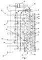
- FIG. 2 shows a schematic development of the control sleeve 38 and the control piston 40, in which case the inventive design of the hydraulic steering device 10 is illustrated.
- the rotary valve control valve 36 includes an input throttle 76, which lies in the radial plane of a channel 77.
- the input throttle 76 includes diameter staggered input holes 78 in the control sleeve 38 and axial input slots 80 in the control piston 40.
- Via the connection line 82 and the connection bore 83 are the input slots 80 to the load terminal 26 (FIGS. FIG. 1 ) of the priority valve 22.
- the shutdown channel 61 lying in another radial plane is connected to the valve 60 via the connection line 70 indicated here.
- the rotary valve control valve 36 further comprises in a further plane twelve commutator holes 84 within the control sleeve 38, which form a Kommutatordrossel 88 both with six axial inlet slots 86 in the control piston 40 and six axial input slots 80.
- the control piston 40 further comprises here indicated drainage slots 90, which allow a connection of the rotary valve control valve 36 to the tank 20 at a corresponding position of the control sleeve 38.
- the shut-off channel 61 is connected to one of the drainage slots 90 via a pressure relief connection 92.
- This pressure relief connection 92 is achieved via a bore 94 in the control sleeve 38 and a slot 96 in the control piston 40.
- This pressure relief connection 92 ensures that in the neutral position, in particular after a build-up of pressure in the shut-off channel 61 and the connecting line 70 at the valve 60 is applied high pressure can dissipate. This prevents a swinging of the valve piston 62 against the voltage applied in the connecting line 70 control pressure. Thus, the associated high-frequency noise can not even arise.
Landscapes
- Engineering & Computer Science (AREA)
- Chemical & Material Sciences (AREA)
- Combustion & Propulsion (AREA)
- Transportation (AREA)
- Mechanical Engineering (AREA)
- Power Steering Mechanism (AREA)
Priority Applications (1)
| Application Number | Priority Date | Filing Date | Title |
|---|---|---|---|
| PL11006303T PL2420430T3 (pl) | 2010-08-20 | 2011-07-30 | Hydrauliczne urządzenie kierujące |
Applications Claiming Priority (1)
| Application Number | Priority Date | Filing Date | Title |
|---|---|---|---|
| DE102010039554A DE102010039554A1 (de) | 2010-08-20 | 2010-08-20 | Hydraulische Lenkeinrichtung |
Publications (3)
| Publication Number | Publication Date |
|---|---|
| EP2420430A2 true EP2420430A2 (fr) | 2012-02-22 |
| EP2420430A3 EP2420430A3 (fr) | 2014-10-29 |
| EP2420430B1 EP2420430B1 (fr) | 2015-12-02 |
Family
ID=44514421
Family Applications (1)
| Application Number | Title | Priority Date | Filing Date |
|---|---|---|---|
| EP11006303.9A Active EP2420430B1 (fr) | 2010-08-20 | 2011-07-30 | Dispositif de direction hydraulique |
Country Status (4)
| Country | Link |
|---|---|
| EP (1) | EP2420430B1 (fr) |
| DE (1) | DE102010039554A1 (fr) |
| DK (1) | DK2420430T3 (fr) |
| PL (1) | PL2420430T3 (fr) |
Cited By (1)
| Publication number | Priority date | Publication date | Assignee | Title |
|---|---|---|---|---|
| EP3527463A1 (fr) * | 2018-02-15 | 2019-08-21 | Hydraulik Nord Fluidtechnik GmbH & Co. KG | Module de direction à isolation de chambre |
Citations (2)
| Publication number | Priority date | Publication date | Assignee | Title |
|---|---|---|---|---|
| EP0746492B1 (fr) | 1994-03-04 | 1998-05-20 | Hydraulik Nord Gmbh | Direction hydraulique a demultiplication variable |
| EP1429954B1 (fr) | 2001-09-26 | 2006-05-24 | Bosch Rexroth AG | Mecanisme de direction hydraulique avec modification de transmission |
Family Cites Families (2)
| Publication number | Priority date | Publication date | Assignee | Title |
|---|---|---|---|---|
| DE102006010695B4 (de) * | 2006-03-08 | 2009-05-14 | Sauer-Danfoss Aps | Hydraulische Lenkung |
| KR101294406B1 (ko) * | 2006-12-04 | 2013-08-08 | 두산인프라코어 주식회사 | 휠로더의 조향 핸들 회전속도 제어장치 |
-
2010
- 2010-08-20 DE DE102010039554A patent/DE102010039554A1/de not_active Withdrawn
-
2011
- 2011-07-30 EP EP11006303.9A patent/EP2420430B1/fr active Active
- 2011-07-30 DK DK11006303.9T patent/DK2420430T3/en active
- 2011-07-30 PL PL11006303T patent/PL2420430T3/pl unknown
Patent Citations (2)
| Publication number | Priority date | Publication date | Assignee | Title |
|---|---|---|---|---|
| EP0746492B1 (fr) | 1994-03-04 | 1998-05-20 | Hydraulik Nord Gmbh | Direction hydraulique a demultiplication variable |
| EP1429954B1 (fr) | 2001-09-26 | 2006-05-24 | Bosch Rexroth AG | Mecanisme de direction hydraulique avec modification de transmission |
Cited By (1)
| Publication number | Priority date | Publication date | Assignee | Title |
|---|---|---|---|---|
| EP3527463A1 (fr) * | 2018-02-15 | 2019-08-21 | Hydraulik Nord Fluidtechnik GmbH & Co. KG | Module de direction à isolation de chambre |
Also Published As
| Publication number | Publication date |
|---|---|
| DE102010039554A1 (de) | 2012-02-23 |
| EP2420430A3 (fr) | 2014-10-29 |
| PL2420430T3 (pl) | 2016-05-31 |
| DK2420430T3 (en) | 2016-03-07 |
| EP2420430B1 (fr) | 2015-12-02 |
Similar Documents
| Publication | Publication Date | Title |
|---|---|---|
| WO2008067935A2 (fr) | Dispositif de réglage | |
| EP3472496B1 (fr) | Dispositif d'actionnement d'un frein de stationnement d'une boîte de vitesses automatique et dispositif de frein de stationnement pour une telle boîte de vitesses automatique | |
| EP3012463B1 (fr) | Agregat hydraulique | |
| DE102018124912B4 (de) | Hydraulische Lenkeinrichtung mit Übersetzungsänderung | |
| EP2647883B1 (fr) | Dispositif de commande hydraulique | |
| EP0746492B1 (fr) | Direction hydraulique a demultiplication variable | |
| EP2929217B1 (fr) | Dispositif destiné à commander le fonctionnement d'un ventilateur appartenant à un système de refroidissement et pouvant être entraîné par un moteur hydraulique | |
| DE2719895C3 (de) | Hilfskraftlenkung für Kraftfahrzeuge | |
| EP2420430B1 (fr) | Dispositif de direction hydraulique | |
| DE2904723A1 (de) | Servolenkvorrichtung | |
| DE69934200T2 (de) | Lastreaktive Lenkeinheit für Lenkzylinder mit ungleichen Flächen | |
| DE3101968A1 (de) | Servolenkvorrichtung fuer fahrzeuge | |
| DE3505623A1 (de) | Hydraulisches wegeventil fuer eine lastdruckkompensierte steuerung | |
| DE102008004691A1 (de) | Fluidverstärker für eine Steuervorrichtung eines Fahrzeuges | |
| EP1409325B1 (fr) | Direction assistee hydraulique de type integree | |
| WO2001017840A1 (fr) | Systeme de direction hydraulique a changement de rapport de transmission | |
| DE102022101020A1 (de) | Hydrauliksystem und Verfahren zum Betreiben eines Hydrauliksystems | |
| DE2508268C3 (de) | Steuerkolben fur hydraulische Druckmittelfolgesteuerungen, insbesondere für ein Lenkventil einer Servolenkeinrichtung von Fahrzeugen | |
| EP1526289B1 (fr) | Distributeur pour un système fluidique | |
| EP0932783A1 (fr) | Soupape de reduction et de commande | |
| DE102018103437B4 (de) | Hydraulische Lenkeinrichtung mit Kammerabschaltung | |
| WO2001042663A1 (fr) | Dispositif de commande hydraulique pour commander deux pressions differentes au niveau d'un consommateur hydraulique | |
| DE102020106437B4 (de) | Fluidsteuereinrichtung, insbesondere als Teil einer hydraulischen Lenkeinheit | |
| DE2733128A1 (de) | Hydrostatische zweikreis-lenkanlage | |
| DE1755033C3 (de) | Servolenkeinrichtung, insbesondere für Kraftfahrzeuge mit hydrostatischer Lenkkraftübertragung |
Legal Events
| Date | Code | Title | Description |
|---|---|---|---|
| AK | Designated contracting states |
Kind code of ref document: A2 Designated state(s): AL AT BE BG CH CY CZ DE DK EE ES FI FR GB GR HR HU IE IS IT LI LT LU LV MC MK MT NL NO PL PT RO RS SE SI SK SM TR |
|
| AX | Request for extension of the european patent |
Extension state: BA ME |
|
| PUAI | Public reference made under article 153(3) epc to a published international application that has entered the european phase |
Free format text: ORIGINAL CODE: 0009012 |
|
| REG | Reference to a national code |
Ref country code: DE Ref legal event code: R079 Ref document number: 502011008445 Country of ref document: DE Free format text: PREVIOUS MAIN CLASS: B62D0005060000 Ipc: B62D0005093000 |
|
| PUAL | Search report despatched |
Free format text: ORIGINAL CODE: 0009013 |
|
| RAP1 | Party data changed (applicant data changed or rights of an application transferred) |
Owner name: HYDRAULIK NORD FLUIDTECHNIK GMBH & CO. KG |
|
| AK | Designated contracting states |
Kind code of ref document: A3 Designated state(s): AL AT BE BG CH CY CZ DE DK EE ES FI FR GB GR HR HU IE IS IT LI LT LU LV MC MK MT NL NO PL PT RO RS SE SI SK SM TR |
|
| AX | Request for extension of the european patent |
Extension state: BA ME |
|
| RIC1 | Information provided on ipc code assigned before grant |
Ipc: B62D 5/097 20060101ALI20140923BHEP Ipc: B62D 5/093 20060101AFI20140923BHEP |
|
| 17P | Request for examination filed |
Effective date: 20150318 |
|
| RBV | Designated contracting states (corrected) |
Designated state(s): AL AT BE BG CH CY CZ DE DK EE ES FI FR GB GR HR HU IE IS IT LI LT LU LV MC MK MT NL NO PL PT RO RS SE SI SK SM TR |
|
| GRAP | Despatch of communication of intention to grant a patent |
Free format text: ORIGINAL CODE: EPIDOSNIGR1 |
|
| INTG | Intention to grant announced |
Effective date: 20150629 |
|
| GRAS | Grant fee paid |
Free format text: ORIGINAL CODE: EPIDOSNIGR3 |
|
| GRAA | (expected) grant |
Free format text: ORIGINAL CODE: 0009210 |
|
| AK | Designated contracting states |
Kind code of ref document: B1 Designated state(s): AL AT BE BG CH CY CZ DE DK EE ES FI FR GB GR HR HU IE IS IT LI LT LU LV MC MK MT NL NO PL PT RO RS SE SI SK SM TR |
|
| REG | Reference to a national code |
Ref country code: GB Ref legal event code: FG4D Free format text: NOT ENGLISH |
|
| REG | Reference to a national code |
Ref country code: AT Ref legal event code: REF Ref document number: 763473 Country of ref document: AT Kind code of ref document: T Effective date: 20151215 Ref country code: CH Ref legal event code: EP |
|
| REG | Reference to a national code |
Ref country code: IE Ref legal event code: FG4D Free format text: LANGUAGE OF EP DOCUMENT: GERMAN |
|
| REG | Reference to a national code |
Ref country code: DE Ref legal event code: R096 Ref document number: 502011008445 Country of ref document: DE |
|
| REG | Reference to a national code |
Ref country code: DK Ref legal event code: T3 Effective date: 20160304 |
|
| REG | Reference to a national code |
Ref country code: NL Ref legal event code: MP Effective date: 20160302 |
|
| REG | Reference to a national code |
Ref country code: LT Ref legal event code: MG4D |
|
| PG25 | Lapsed in a contracting state [announced via postgrant information from national office to epo] |
Ref country code: LT Free format text: LAPSE BECAUSE OF FAILURE TO SUBMIT A TRANSLATION OF THE DESCRIPTION OR TO PAY THE FEE WITHIN THE PRESCRIBED TIME-LIMIT Effective date: 20151202 Ref country code: NO Free format text: LAPSE BECAUSE OF FAILURE TO SUBMIT A TRANSLATION OF THE DESCRIPTION OR TO PAY THE FEE WITHIN THE PRESCRIBED TIME-LIMIT Effective date: 20160302 Ref country code: ES Free format text: LAPSE BECAUSE OF FAILURE TO SUBMIT A TRANSLATION OF THE DESCRIPTION OR TO PAY THE FEE WITHIN THE PRESCRIBED TIME-LIMIT Effective date: 20151202 |
|
| PG25 | Lapsed in a contracting state [announced via postgrant information from national office to epo] |
Ref country code: SE Free format text: LAPSE BECAUSE OF FAILURE TO SUBMIT A TRANSLATION OF THE DESCRIPTION OR TO PAY THE FEE WITHIN THE PRESCRIBED TIME-LIMIT Effective date: 20151202 Ref country code: LV Free format text: LAPSE BECAUSE OF FAILURE TO SUBMIT A TRANSLATION OF THE DESCRIPTION OR TO PAY THE FEE WITHIN THE PRESCRIBED TIME-LIMIT Effective date: 20151202 Ref country code: FI Free format text: LAPSE BECAUSE OF FAILURE TO SUBMIT A TRANSLATION OF THE DESCRIPTION OR TO PAY THE FEE WITHIN THE PRESCRIBED TIME-LIMIT Effective date: 20151202 Ref country code: NL Free format text: LAPSE BECAUSE OF FAILURE TO SUBMIT A TRANSLATION OF THE DESCRIPTION OR TO PAY THE FEE WITHIN THE PRESCRIBED TIME-LIMIT Effective date: 20151202 Ref country code: GR Free format text: LAPSE BECAUSE OF FAILURE TO SUBMIT A TRANSLATION OF THE DESCRIPTION OR TO PAY THE FEE WITHIN THE PRESCRIBED TIME-LIMIT Effective date: 20160303 Ref country code: RS Free format text: LAPSE BECAUSE OF FAILURE TO SUBMIT A TRANSLATION OF THE DESCRIPTION OR TO PAY THE FEE WITHIN THE PRESCRIBED TIME-LIMIT Effective date: 20151202 |
|
| PG25 | Lapsed in a contracting state [announced via postgrant information from national office to epo] |
Ref country code: IS Free format text: LAPSE BECAUSE OF FAILURE TO SUBMIT A TRANSLATION OF THE DESCRIPTION OR TO PAY THE FEE WITHIN THE PRESCRIBED TIME-LIMIT Effective date: 20151202 |
|
| PG25 | Lapsed in a contracting state [announced via postgrant information from national office to epo] |
Ref country code: CZ Free format text: LAPSE BECAUSE OF FAILURE TO SUBMIT A TRANSLATION OF THE DESCRIPTION OR TO PAY THE FEE WITHIN THE PRESCRIBED TIME-LIMIT Effective date: 20151202 |
|
| PG25 | Lapsed in a contracting state [announced via postgrant information from national office to epo] |
Ref country code: IS Free format text: LAPSE BECAUSE OF FAILURE TO SUBMIT A TRANSLATION OF THE DESCRIPTION OR TO PAY THE FEE WITHIN THE PRESCRIBED TIME-LIMIT Effective date: 20160402 Ref country code: PT Free format text: LAPSE BECAUSE OF FAILURE TO SUBMIT A TRANSLATION OF THE DESCRIPTION OR TO PAY THE FEE WITHIN THE PRESCRIBED TIME-LIMIT Effective date: 20160404 Ref country code: RO Free format text: LAPSE BECAUSE OF FAILURE TO SUBMIT A TRANSLATION OF THE DESCRIPTION OR TO PAY THE FEE WITHIN THE PRESCRIBED TIME-LIMIT Effective date: 20151202 Ref country code: SK Free format text: LAPSE BECAUSE OF FAILURE TO SUBMIT A TRANSLATION OF THE DESCRIPTION OR TO PAY THE FEE WITHIN THE PRESCRIBED TIME-LIMIT Effective date: 20151202 Ref country code: SM Free format text: LAPSE BECAUSE OF FAILURE TO SUBMIT A TRANSLATION OF THE DESCRIPTION OR TO PAY THE FEE WITHIN THE PRESCRIBED TIME-LIMIT Effective date: 20151202 Ref country code: EE Free format text: LAPSE BECAUSE OF FAILURE TO SUBMIT A TRANSLATION OF THE DESCRIPTION OR TO PAY THE FEE WITHIN THE PRESCRIBED TIME-LIMIT Effective date: 20151202 |
|
| REG | Reference to a national code |
Ref country code: DE Ref legal event code: R097 Ref document number: 502011008445 Country of ref document: DE |
|
| PLBE | No opposition filed within time limit |
Free format text: ORIGINAL CODE: 0009261 |
|
| STAA | Information on the status of an ep patent application or granted ep patent |
Free format text: STATUS: NO OPPOSITION FILED WITHIN TIME LIMIT |
|
| 26N | No opposition filed |
Effective date: 20160905 |
|
| PG25 | Lapsed in a contracting state [announced via postgrant information from national office to epo] |
Ref country code: SI Free format text: LAPSE BECAUSE OF FAILURE TO SUBMIT A TRANSLATION OF THE DESCRIPTION OR TO PAY THE FEE WITHIN THE PRESCRIBED TIME-LIMIT Effective date: 20151202 |
|
| PG25 | Lapsed in a contracting state [announced via postgrant information from national office to epo] |
Ref country code: BE Free format text: LAPSE BECAUSE OF NON-PAYMENT OF DUE FEES Effective date: 20160731 |
|
| REG | Reference to a national code |
Ref country code: CH Ref legal event code: PL |
|
| GBPC | Gb: european patent ceased through non-payment of renewal fee |
Effective date: 20160730 |
|
| PG25 | Lapsed in a contracting state [announced via postgrant information from national office to epo] |
Ref country code: MC Free format text: LAPSE BECAUSE OF FAILURE TO SUBMIT A TRANSLATION OF THE DESCRIPTION OR TO PAY THE FEE WITHIN THE PRESCRIBED TIME-LIMIT Effective date: 20151202 |
|
| PG25 | Lapsed in a contracting state [announced via postgrant information from national office to epo] |
Ref country code: FR Free format text: LAPSE BECAUSE OF NON-PAYMENT OF DUE FEES Effective date: 20160801 Ref country code: CH Free format text: LAPSE BECAUSE OF NON-PAYMENT OF DUE FEES Effective date: 20160731 Ref country code: LI Free format text: LAPSE BECAUSE OF NON-PAYMENT OF DUE FEES Effective date: 20160731 |
|
| REG | Reference to a national code |
Ref country code: FR Ref legal event code: ST Effective date: 20170331 |
|
| REG | Reference to a national code |
Ref country code: IE Ref legal event code: MM4A |
|
| PG25 | Lapsed in a contracting state [announced via postgrant information from national office to epo] |
Ref country code: GB Free format text: LAPSE BECAUSE OF NON-PAYMENT OF DUE FEES Effective date: 20160730 |
|
| PG25 | Lapsed in a contracting state [announced via postgrant information from national office to epo] |
Ref country code: IE Free format text: LAPSE BECAUSE OF NON-PAYMENT OF DUE FEES Effective date: 20160730 |
|
| PG25 | Lapsed in a contracting state [announced via postgrant information from national office to epo] |
Ref country code: LU Free format text: LAPSE BECAUSE OF NON-PAYMENT OF DUE FEES Effective date: 20160730 |
|
| REG | Reference to a national code |
Ref country code: AT Ref legal event code: MM01 Ref document number: 763473 Country of ref document: AT Kind code of ref document: T Effective date: 20160730 |
|
| PG25 | Lapsed in a contracting state [announced via postgrant information from national office to epo] |
Ref country code: AT Free format text: LAPSE BECAUSE OF NON-PAYMENT OF DUE FEES Effective date: 20160730 |
|
| PG25 | Lapsed in a contracting state [announced via postgrant information from national office to epo] |
Ref country code: CY Free format text: LAPSE BECAUSE OF FAILURE TO SUBMIT A TRANSLATION OF THE DESCRIPTION OR TO PAY THE FEE WITHIN THE PRESCRIBED TIME-LIMIT Effective date: 20151202 Ref country code: HU Free format text: LAPSE BECAUSE OF FAILURE TO SUBMIT A TRANSLATION OF THE DESCRIPTION OR TO PAY THE FEE WITHIN THE PRESCRIBED TIME-LIMIT; INVALID AB INITIO Effective date: 20110730 |
|
| PG25 | Lapsed in a contracting state [announced via postgrant information from national office to epo] |
Ref country code: HR Free format text: LAPSE BECAUSE OF FAILURE TO SUBMIT A TRANSLATION OF THE DESCRIPTION OR TO PAY THE FEE WITHIN THE PRESCRIBED TIME-LIMIT Effective date: 20151202 Ref country code: MK Free format text: LAPSE BECAUSE OF FAILURE TO SUBMIT A TRANSLATION OF THE DESCRIPTION OR TO PAY THE FEE WITHIN THE PRESCRIBED TIME-LIMIT Effective date: 20151202 Ref country code: TR Free format text: LAPSE BECAUSE OF FAILURE TO SUBMIT A TRANSLATION OF THE DESCRIPTION OR TO PAY THE FEE WITHIN THE PRESCRIBED TIME-LIMIT Effective date: 20151202 Ref country code: MT Free format text: LAPSE BECAUSE OF FAILURE TO SUBMIT A TRANSLATION OF THE DESCRIPTION OR TO PAY THE FEE WITHIN THE PRESCRIBED TIME-LIMIT Effective date: 20151202 |
|
| PG25 | Lapsed in a contracting state [announced via postgrant information from national office to epo] |
Ref country code: AL Free format text: LAPSE BECAUSE OF FAILURE TO SUBMIT A TRANSLATION OF THE DESCRIPTION OR TO PAY THE FEE WITHIN THE PRESCRIBED TIME-LIMIT Effective date: 20151202 |
|
| PGFP | Annual fee paid to national office [announced via postgrant information from national office to epo] |
Ref country code: DK Payment date: 20190723 Year of fee payment: 9 |
|
| PGFP | Annual fee paid to national office [announced via postgrant information from national office to epo] |
Ref country code: BG Payment date: 20190722 Year of fee payment: 9 Ref country code: PL Payment date: 20190723 Year of fee payment: 9 |
|
| REG | Reference to a national code |
Ref country code: DE Ref legal event code: R081 Ref document number: 502011008445 Country of ref document: DE Owner name: WHITE DRIVE MOTORS AND STEERING GMBH, DE Free format text: FORMER OWNER: DANFOSS POWER SOLUTIONS PARCHIM GMBH & CO. KG, 19370 PARCHIM, DE Ref country code: DE Ref legal event code: R081 Ref document number: 502011008445 Country of ref document: DE Owner name: WHITE DRIVE MOTORS AND STEERING GMBH, DE Free format text: FORMER OWNER: HYDRAULIK NORD FLUIDTECHNIK GMBH & CO. KG, 19370 PARCHIM, DE Ref country code: DE Ref legal event code: R081 Ref document number: 502011008445 Country of ref document: DE Owner name: WHITE DRIVE MOTORS AND STEERING SP. Z O.O., PL Free format text: FORMER OWNER: DANFOSS POWER SOLUTIONS PARCHIM GMBH & CO. KG, 19370 PARCHIM, DE Ref country code: DE Ref legal event code: R081 Ref document number: 502011008445 Country of ref document: DE Owner name: WHITE DRIVE MOTORS AND STEERING SP. Z O.O., PL Free format text: FORMER OWNER: HYDRAULIK NORD FLUIDTECHNIK GMBH & CO. KG, 19370 PARCHIM, DE Ref country code: DE Ref legal event code: R082 Ref document number: 502011008445 Country of ref document: DE Representative=s name: GULDE & PARTNER PATENT- UND RECHTSANWALTSKANZL, DE Ref country code: DE Ref legal event code: R081 Ref document number: 502011008445 Country of ref document: DE Owner name: DANFOSS POWER SOLUTIONS APS, DK Free format text: FORMER OWNER: DANFOSS POWER SOLUTIONS PARCHIM GMBH & CO. KG, 19370 PARCHIM, DE Ref country code: DE Ref legal event code: R081 Ref document number: 502011008445 Country of ref document: DE Owner name: DANFOSS POWER SOLUTIONS APS, DK Free format text: FORMER OWNER: HYDRAULIK NORD FLUIDTECHNIK GMBH & CO. KG, 19370 PARCHIM, DE Ref country code: DE Ref legal event code: R081 Ref document number: 502011008445 Country of ref document: DE Owner name: DANFOSS POWER SOLUTIONS PARCHIM GMBH, DE Free format text: FORMER OWNER: HYDRAULIK NORD FLUIDTECHNIK GMBH & CO. KG, 19370 PARCHIM, DE Ref country code: DE Ref legal event code: R081 Ref document number: 502011008445 Country of ref document: DE Owner name: DANFOSS POWER SOLUTIONS PARCHIM GMBH, DE Free format text: FORMER OWNER: DANFOSS POWER SOLUTIONS PARCHIM GMBH & CO. KG, 19370 PARCHIM, DE |
|
| REG | Reference to a national code |
Ref country code: DE Ref legal event code: R081 Ref document number: 502011008445 Country of ref document: DE Owner name: WHITE DRIVE MOTORS AND STEERING GMBH, DE Free format text: FORMER OWNER: DANFOSS POWER SOLUTIONS APS, NORDBORG, DK Ref country code: DE Ref legal event code: R081 Ref document number: 502011008445 Country of ref document: DE Owner name: WHITE DRIVE MOTORS AND STEERING SP. Z O.O., PL Free format text: FORMER OWNER: DANFOSS POWER SOLUTIONS APS, NORDBORG, DK Ref country code: DE Ref legal event code: R082 Ref document number: 502011008445 Country of ref document: DE Representative=s name: GULDE & PARTNER PATENT- UND RECHTSANWALTSKANZL, DE Ref country code: DE Ref legal event code: R081 Ref document number: 502011008445 Country of ref document: DE Owner name: DANFOSS POWER SOLUTIONS PARCHIM GMBH, DE Free format text: FORMER OWNER: DANFOSS POWER SOLUTIONS APS, NORDBORG, DK |
|
| REG | Reference to a national code |
Ref country code: DK Ref legal event code: EBP Effective date: 20200731 |
|
| PG25 | Lapsed in a contracting state [announced via postgrant information from national office to epo] |
Ref country code: BG Free format text: LAPSE BECAUSE OF NON-PAYMENT OF DUE FEES Effective date: 20210131 |
|
| PG25 | Lapsed in a contracting state [announced via postgrant information from national office to epo] |
Ref country code: DK Free format text: LAPSE BECAUSE OF NON-PAYMENT OF DUE FEES Effective date: 20200731 |
|
| REG | Reference to a national code |
Ref country code: DE Ref legal event code: R081 Ref document number: 502011008445 Country of ref document: DE Owner name: WHITE DRIVE MOTORS AND STEERING GMBH, DE Free format text: FORMER OWNER: DANFOSS POWER SOLUTIONS PARCHIM GMBH, 19370 PARCHIM, DE Ref country code: DE Ref legal event code: R081 Ref document number: 502011008445 Country of ref document: DE Owner name: WHITE DRIVE MOTORS AND STEERING SP. Z O.O., PL Free format text: FORMER OWNER: DANFOSS POWER SOLUTIONS PARCHIM GMBH, 19370 PARCHIM, DE |
|
| PG25 | Lapsed in a contracting state [announced via postgrant information from national office to epo] |
Ref country code: PL Free format text: LAPSE BECAUSE OF NON-PAYMENT OF DUE FEES Effective date: 20200730 |
|
| P01 | Opt-out of the competence of the unified patent court (upc) registered |
Effective date: 20230517 |
|
| REG | Reference to a national code |
Ref country code: DE Ref legal event code: R082 Ref document number: 502011008445 Country of ref document: DE Representative=s name: DENNEMEYER & ASSOCIATES RECHTSANWALTSGESELLSCH, DE Ref country code: DE Ref legal event code: R081 Ref document number: 502011008445 Country of ref document: DE Owner name: WHITE DRIVE MOTORS AND STEERING SP. Z O.O., PL Free format text: FORMER OWNER: WHITE DRIVE MOTORS AND STEERING GMBH, 19370 PARCHIM, DE |
|
| PGFP | Annual fee paid to national office [announced via postgrant information from national office to epo] |
Ref country code: DE Payment date: 20250722 Year of fee payment: 15 |
|
| PGFP | Annual fee paid to national office [announced via postgrant information from national office to epo] |
Ref country code: IT Payment date: 20250724 Year of fee payment: 15 |