EP3527463A1 - Module de direction à isolation de chambre - Google Patents
Module de direction à isolation de chambre Download PDFInfo
- Publication number
- EP3527463A1 EP3527463A1 EP19152597.1A EP19152597A EP3527463A1 EP 3527463 A1 EP3527463 A1 EP 3527463A1 EP 19152597 A EP19152597 A EP 19152597A EP 3527463 A1 EP3527463 A1 EP 3527463A1
- Authority
- EP
- European Patent Office
- Prior art keywords
- steering
- hand
- channel
- channels
- annular channel
- Prior art date
- Legal status (The legal status is an assumption and is not a legal conclusion. Google has not performed a legal analysis and makes no representation as to the accuracy of the status listed.)
- Withdrawn
Links
- 230000009849 deactivation Effects 0.000 title claims abstract description 5
- 238000006073 displacement reaction Methods 0.000 claims description 7
- 238000000034 method Methods 0.000 claims description 2
- 230000008569 process Effects 0.000 claims description 2
- 239000012530 fluid Substances 0.000 description 4
- 239000010720 hydraulic oil Substances 0.000 description 3
- 239000003921 oil Substances 0.000 description 2
- 238000000926 separation method Methods 0.000 description 2
- 230000004888 barrier function Effects 0.000 description 1
- 230000008901 benefit Effects 0.000 description 1
- 230000015572 biosynthetic process Effects 0.000 description 1
- 238000006243 chemical reaction Methods 0.000 description 1
- 230000007423 decrease Effects 0.000 description 1
- 230000001419 dependent effect Effects 0.000 description 1
- 238000002955 isolation Methods 0.000 description 1
- 230000007935 neutral effect Effects 0.000 description 1
- 230000009467 reduction Effects 0.000 description 1
Images

Classifications
-
- B—PERFORMING OPERATIONS; TRANSPORTING
- B62—LAND VEHICLES FOR TRAVELLING OTHERWISE THAN ON RAILS
- B62D—MOTOR VEHICLES; TRAILERS
- B62D5/00—Power-assisted or power-driven steering
- B62D5/06—Power-assisted or power-driven steering fluid, i.e. using a pressurised fluid for most or all the force required for steering a vehicle
- B62D5/30—Safety devices, e.g. alternate emergency power supply or transmission means to ensure steering upon failure of the primary steering means
- B62D5/32—Safety devices, e.g. alternate emergency power supply or transmission means to ensure steering upon failure of the primary steering means for telemotor systems
Definitions
- the invention relates to a steering unit with chamber shutdown according to the preamble of patent claim 1.
- the oil power supply such as a servo pump
- they automatically reduce a funded by a metering pump in a steering cylinder volume of hydraulic fluid that passes per revolution of the steering wheel in the steering cylinder and thus reduce the driver's effort in the steering of the vehicle in terms of a gear ratio.
- the reduction is for example in the range of 50%, so that the necessary steering power decreases by about the same amount.
- EP 0 746 492 B1 describes such a conventional hydraulic steering device with chamber cutoff, which comprises a control valve and a metering pump with a plurality of displacement chambers.
- the control valve has a control piston controllable by a steering wheel and a control sleeve mechanically connected to a rotor of the metering pump.
- the spool and the control sleeve are equipped with channels for hydraulic fluid.
- the channels correspond with each other and with the metering pump.
- the channels connect the displacement chambers of the metering pump, via a supply line with several parallel inlet throttles with a steering cylinder and the steering cylinder, via a return line with several parallel return throttles with a return port.
- At least one level of the inlet throttles constantly in communication with the steering cylinder.
- Another level of the inlet throttles is by means of one of the pressure difference before and after the metering pump controllable switching unit with a, connected to a supply pump inlet connection connectable or connectable to a drain port, which in turn is connected to a tank.
- the first and the second level are separated by a separating element, suitably by a respective non-spring-loaded check valve.
- the invention relates to a hydraulic steering device with chamber shutdown, with at least one control sleeve and a control piston, wherein the control sleeve has at least two annular channels for right-hand steering and two ring channels for left-hand drive, which are separated from each other by a check valve.
- the switch-off channel necessary for the chamber shut-off is placed centrally between the ring channels for right-hand steering and the ring channels for left-hand steering.
- two ring channels for right-hand drive two ring channels are provided for left-hand steering.
- the shutdown channel those ring channel for right-hand drive and those ring channel for left-hand drive, which is adjacent to the cut-off, flanked directly.
- the shutdown channel is arranged in the manner between the ring channels for right and left, that it is closest to the channels that are switched off in emergency mode.
- annular channel is arranged between the last annular channel for left-hand steering and the annular channel for drain, which is connected to the steering input.
- the hydraulic steering device comprises a control valve and a metering pump, wherein the control valve has the control piston controllable by a steering wheel and the control sleeve, which with a rotor of the metering pump is mechanically connected and the control piston and the control sleeve with each other and with the metering pump corresponding channels and the metering pump has a plurality of displacement chambers, some of which with one of the cylinder ports and the other via the shutdown in cooperation with a switching unit either with one of the cylinder ports or the steering sequence or steering input of the steering device are connected.
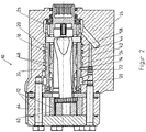
- the steering device according to the invention with chamber shutdown like the, for example in the FIGS. 1 and 2 be shown, conventional embodiments, wherein the inventive arrangement of Abschaltkanals relative to the ring channels is always observed.
- the invention is applicable to steering units with chamber shutdown either with open or closed neutral position or LS version both with and without reaction.
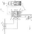
- FIG. 1 shows essential components of a conventional hydraulic steering device with chamber shutdown 10, which contribute to reducing the delivery volume of the metering pump 12 in case of failure of the power assistance.
- the shut-off channel 14 of the control sleeve 16 can be fluidly connected, for example, with every second cylinder inlet slot 18 of the control piston 20. Because of the clarity the control sleeve 16 and the control piston 20 are shown side by side here. These are in the assembled state, as indicated by the dashed longitudinal axis L, composed.
- the shut-off channel 14 establishes a fluid connection with the detected cylinder inlet slots 18, for the purpose of forwarding hydraulic oil to a switching unit 22 (see FIG FIG.
- the switching unit 22 then supplies the hydraulic oil either to a steering outlet 26 or again to a steering inlet 28 of the hydraulic steering device.
- the shut-off channel 14 is executed by a recessed groove 30 in the control sleeve 16.
- the cut-off channel 14 is arranged between commutator bores 32 and a first annular channel for right-hand steering 34. If the steering piston 36 of the steering cylinder 38 is now moved against its right stop 40 during steering operation, hydraulic pressure is applied in a known manner to the first annular channel for right-hand steering 34 and second annular channel for right-hand steering 42. As in FIG.
- the first annular channel for right-hand steering 34 is flanked by the Abschaltkanal 14. Since the shutdown channel 14 is under the same hydraulic pressure, no leakage flow of hydraulic oil flows from the first annular channel for right-hand steering 34 in the direction of Abschaltkanals 14. However, the second annular channel for right-hand steering 42, in addition to the first annular channel for right-hand steering 34, and the first annular channel for left-hand drive 44 flanked. This is connected to stop the steering piston 36 on the right stop 40 to the steering drain 26. Accordingly, there is a pressure difference between the second annular channel for right-hand steering 42 and the first annular channel for left-hand steering 44, so that a leakage current can occur here, which can lead to increased slip in the steering. The slip can be high and beyond also uneven with respect to a left or right-hand steering, which means significant disadvantages for the steering behavior.
- FIGS. 1 and 2 Furthermore, features that are commonly associated with the described conventional hydraulic steering device with chamber shutdown 10 and which are familiar to the expert. Shown are, for example, that the control sleeve 16 and the control piston 20 together form a control valve 48.
- the control sleeve 16 is further comprised of an annular passage for the inlet port 28, which opens into the cylinder port 50 and an annular channel for the steering flow 26, which opens into the cylinder port 52 and annular channels 34 and 42, which open into the cylinder connection for right-hand steering 54 and annular channels 44 and 58, which open into the cylinder connection for left-hand steering 56.
- the steering wheel 60, a rotor 62 and displacement chambers 64 of the metering pump 12 are shown.
- the channels 66 correspond to the metering pump 12.
- a check valve 72 for the separation of the second right-hand annulus 42 from the first annulus 34 and a check valve 74 for the second annulus left-annulus isolation 58 from the first annulus 44 are shown.
- the separation takes place in emergency mode and causes the respectively funded oil drains in emergency operation from the second annular channel in the connected to the outlet or inlet first annular channel.
- FIG. 3 shows how a hydraulic steering device according to the invention with Kammerabscrien 68 differs from the conventional hydraulic steering device with chamber shutdown 10. With respect to those features which do not differ or where this is not essential to the invention, identical reference numerals are used.
- the control sleeve 16 of the hydraulic steering device according to the invention with Kammerabscrien 68 also has a first annular channel for right-hand steering 34, a second annular channel for right-hand steering 42, a first annular channel for left-hand steering 44 and a second annular channel for left-hand steering 58 in the embodiment shown.
- the switch-off channel 70 is provided between an adjacent annular channel for right-hand steering 42 and annular channel for left-hand steering 44. This is in the case of a right or left-hand drive against a stop 40 or 46 always under the same hydraulic pressure as either the ring channels for right-hand steering 34, 42 or as the ring channels for left-hand steering 44, 58.
- Abschaltkanal located 70 a pressure barrier, which prevents a leakage current from the ring channels for right-hand steering 34, 42 to the ring channels for left-hand steering 44, 58 (or vice versa).
- the shutdown channel 70 flanks the second annular channel for right-hand steering 42 and the first annular channel for left-hand steering 44, ie the annular channels which are connected in emergency operation with the drain 26 or the inlet 28 directly.
- first annular channel for right-hand steering 34 is arranged next to the commutator bores 32 of the control sleeve 16, so that no leakage current can occur in this direction.
- an additional annular channel 78 is provided there in addition to the second annular channel for left-hand steering 58.
- the additional annular channel 78 is connected to the annular channel steering inlet 28 of the control sleeve 16 via a connecting line 80.
- the additional annular channel 78 is thus arranged between the last annular channel for left-hand steering 58 and the outlet 26.
- the hydraulic steering device with chamber deactivation 68 can comprise further features in a known manner (cf. FIGS. 1 and 2 ). These include in particular the formation of the control valve 48 and the metering pump 12, wherein the control valve 48 has the controllable by the steering wheel 60 control piston 20 and the control sleeve 16 which is mechanically connected to the rotor 62 of the metering pump 12 and the control piston 20 and the control sleeve 16th the one another and with the metering pump 12 corresponding channels 66 and the metering pump 12 has a plurality of displacement chambers 64, some of which constantly with one of the cylinder ports (54, 56) and the other via the Abschaltkanal 70 in cooperation with the switching unit 22 either with one of Cylinder ports (54, 56) or the steering flow 26 or steering inlet 28 of the steering device 68 are connected.
Landscapes
- Engineering & Computer Science (AREA)
- Chemical & Material Sciences (AREA)
- Combustion & Propulsion (AREA)
- Transportation (AREA)
- Mechanical Engineering (AREA)
- Power Steering Mechanism (AREA)
Applications Claiming Priority (1)
| Application Number | Priority Date | Filing Date | Title |
|---|---|---|---|
| DE102018103437.7A DE102018103437B4 (de) | 2018-02-15 | 2018-02-15 | Hydraulische Lenkeinrichtung mit Kammerabschaltung |
Publications (1)
| Publication Number | Publication Date |
|---|---|
| EP3527463A1 true EP3527463A1 (fr) | 2019-08-21 |
Family
ID=65041681
Family Applications (1)
| Application Number | Title | Priority Date | Filing Date |
|---|---|---|---|
| EP19152597.1A Withdrawn EP3527463A1 (fr) | 2018-02-15 | 2019-01-18 | Module de direction à isolation de chambre |
Country Status (2)
| Country | Link |
|---|---|
| EP (1) | EP3527463A1 (fr) |
| DE (1) | DE102018103437B4 (fr) |
Citations (5)
| Publication number | Priority date | Publication date | Assignee | Title |
|---|---|---|---|---|
| DE2228531A1 (de) * | 1971-07-22 | 1973-02-01 | Sasnowski Hydraulik Nord | Hydrostatische lenkeinrichtung |
| DE19511501A1 (de) * | 1995-03-29 | 1996-10-02 | Danfoss As | Hydraulische Steuereinrichtung |
| EP0746492A1 (fr) * | 1994-03-04 | 1996-12-11 | Hydraulik Nord Gmbh | Direction hydraulique a demultiplication variable |
| EP2420430A2 (fr) * | 2010-08-20 | 2012-02-22 | Robert Bosch GmbH | Dispositif de direction hydraulique |
| EP2610142A1 (fr) * | 2011-12-27 | 2013-07-03 | Sauer-Danfoss ApS | Dispositif de direction hydraulique |
-
2018
- 2018-02-15 DE DE102018103437.7A patent/DE102018103437B4/de active Active
-
2019
- 2019-01-18 EP EP19152597.1A patent/EP3527463A1/fr not_active Withdrawn
Patent Citations (5)
| Publication number | Priority date | Publication date | Assignee | Title |
|---|---|---|---|---|
| DE2228531A1 (de) * | 1971-07-22 | 1973-02-01 | Sasnowski Hydraulik Nord | Hydrostatische lenkeinrichtung |
| EP0746492A1 (fr) * | 1994-03-04 | 1996-12-11 | Hydraulik Nord Gmbh | Direction hydraulique a demultiplication variable |
| DE19511501A1 (de) * | 1995-03-29 | 1996-10-02 | Danfoss As | Hydraulische Steuereinrichtung |
| EP2420430A2 (fr) * | 2010-08-20 | 2012-02-22 | Robert Bosch GmbH | Dispositif de direction hydraulique |
| EP2610142A1 (fr) * | 2011-12-27 | 2013-07-03 | Sauer-Danfoss ApS | Dispositif de direction hydraulique |
Also Published As
| Publication number | Publication date |
|---|---|
| DE102018103437B4 (de) | 2019-10-17 |
| DE102018103437A1 (de) | 2019-08-22 |
Similar Documents
| Publication | Publication Date | Title |
|---|---|---|
| EP1780420B1 (fr) | Unité hydraulique d'alimentation en pression et unité de traitement électro-hydraulique | |
| DE1755387B2 (de) | Hydrostatische lenkeinrichtung, insbesondere fuer schwere fahrzeuge | |
| WO2014131393A1 (fr) | Pompe à vis se composant d'au moins deux parties | |
| DE2541486A1 (de) | Steuergeraet fuer druckmittelbetaetigte vorrichtungen | |
| EP2964359B1 (fr) | Dispositif de filtration | |
| DE3802904A1 (de) | Servounterstuetzte lenkanlage | |
| EP2929217B1 (fr) | Dispositif destiné à commander le fonctionnement d'un ventilateur appartenant à un système de refroidissement et pouvant être entraîné par un moteur hydraulique | |
| DE2136878C2 (de) | Hydraulikanlage mit zwei Druckmittelquellen und mehreren Hydromotoren | |
| DE69217460T2 (de) | Hydraulisches Ventil mit integriertem Hilfsventil | |
| DE102018103437B4 (de) | Hydraulische Lenkeinrichtung mit Kammerabschaltung | |
| DE3031230C2 (de) | Hydrostatische Hilfskraftlenkeinrichtung | |
| WO2019219492A1 (fr) | Soupape | |
| DE3135098A1 (de) | Ventilaufbau, umfassend ein pumpensteuer- bzw. -regelventil und eine entlastungsanordnung | |
| WO2001017840A1 (fr) | Systeme de direction hydraulique a changement de rapport de transmission | |
| WO1995033136A1 (fr) | Systeme de regulation d'un dispositif de levage avec soupape de regulation | |
| EP0839703B1 (fr) | Système de direction hydraulique à démultiplication variable et amplification de débit | |
| DE3229217C2 (de) | Ventilblock | |
| DE102008023034B4 (de) | Hydraulische Lenkeinrichtung | |
| DE19724432C1 (de) | Hydraulischer Steuerblock für Teleskopzylinder von Kippfahrzeugen oder ähnlichen Vorrichtungen | |
| DE2917298C2 (de) | Drehschiebereinrichtung zur Steuerung eines hydrostatischen Servoantriebs | |
| EP2420430B1 (fr) | Dispositif de direction hydraulique | |
| DE2733128A1 (de) | Hydrostatische zweikreis-lenkanlage | |
| EP1765656B1 (fr) | Soupape a tiroir rotatif pour systeme de direction assistee hydraulique | |
| DE102020106437B4 (de) | Fluidsteuereinrichtung, insbesondere als Teil einer hydraulischen Lenkeinheit | |
| DE102014212717B4 (de) | Hydraulische Lenkeinrichtung |
Legal Events
| Date | Code | Title | Description |
|---|---|---|---|
| PUAI | Public reference made under article 153(3) epc to a published international application that has entered the european phase |
Free format text: ORIGINAL CODE: 0009012 |
|
| STAA | Information on the status of an ep patent application or granted ep patent |
Free format text: STATUS: THE APPLICATION HAS BEEN PUBLISHED |
|
| AK | Designated contracting states |
Kind code of ref document: A1 Designated state(s): AL AT BE BG CH CY CZ DE DK EE ES FI FR GB GR HR HU IE IS IT LI LT LU LV MC MK MT NL NO PL PT RO RS SE SI SK SM TR |
|
| AX | Request for extension of the european patent |
Extension state: BA ME |
|
| STAA | Information on the status of an ep patent application or granted ep patent |
Free format text: STATUS: REQUEST FOR EXAMINATION WAS MADE |
|
| RAP1 | Party data changed (applicant data changed or rights of an application transferred) |
Owner name: DANFOSS POWER SOLUTIONS PARCHIM GMBH & CO. KG |
|
| RAP1 | Party data changed (applicant data changed or rights of an application transferred) |
Owner name: DANFOSS POWER SOLUTIONS APS |
|
| 17P | Request for examination filed |
Effective date: 20200207 |
|
| RBV | Designated contracting states (corrected) |
Designated state(s): AL AT BE BG CH CY CZ DE DK EE ES FI FR GB GR HR HU IE IS IT LI LT LU LV MC MK MT NL NO PL PT RO RS SE SI SK SM TR |
|
| GRAP | Despatch of communication of intention to grant a patent |
Free format text: ORIGINAL CODE: EPIDOSNIGR1 |
|
| STAA | Information on the status of an ep patent application or granted ep patent |
Free format text: STATUS: GRANT OF PATENT IS INTENDED |
|
| INTG | Intention to grant announced |
Effective date: 20200415 |
|
| RAP1 | Party data changed (applicant data changed or rights of an application transferred) |
Owner name: DANFOSS POWER SOLUTIONS PARCHIM GMBH |
|
| STAA | Information on the status of an ep patent application or granted ep patent |
Free format text: STATUS: THE APPLICATION IS DEEMED TO BE WITHDRAWN |
|
| 18D | Application deemed to be withdrawn |
Effective date: 20200826 |