EP2420681B1 - Hydraulischer Linearantrieb - Google Patents
Hydraulischer Linearantrieb Download PDFInfo
- Publication number
- EP2420681B1 EP2420681B1 EP11006709.7A EP11006709A EP2420681B1 EP 2420681 B1 EP2420681 B1 EP 2420681B1 EP 11006709 A EP11006709 A EP 11006709A EP 2420681 B1 EP2420681 B1 EP 2420681B1
- Authority
- EP
- European Patent Office
- Prior art keywords
- pressure
- linear drive
- pressure space
- valve
- hydraulic
- Prior art date
- Legal status (The legal status is an assumption and is not a legal conclusion. Google has not performed a legal analysis and makes no representation as to the accuracy of the status listed.)
- Active
Links
Images

Classifications
-
- F—MECHANICAL ENGINEERING; LIGHTING; HEATING; WEAPONS; BLASTING
- F15—FLUID-PRESSURE ACTUATORS; HYDRAULICS OR PNEUMATICS IN GENERAL
- F15B—SYSTEMS ACTING BY MEANS OF FLUIDS IN GENERAL; FLUID-PRESSURE ACTUATORS, e.g. SERVOMOTORS; DETAILS OF FLUID-PRESSURE SYSTEMS, NOT OTHERWISE PROVIDED FOR
- F15B11/00—Servomotor systems without provision for follow-up action ; Circuits therefor
- F15B11/02—Systems essentially incorporating special features for controlling the speed or the actuating force of an output member
- F15B11/028—Systems essentially incorporating special features for controlling the speed or the actuating force of an output member for controlling the actuating force
- F15B11/036—Systems essentially incorporating special features for controlling the speed or the actuating force of an output member for controlling the actuating force by means of servomotors having a plurality of working chambers
-
- F—MECHANICAL ENGINEERING; LIGHTING; HEATING; WEAPONS; BLASTING
- F15—FLUID-PRESSURE ACTUATORS; HYDRAULICS OR PNEUMATICS IN GENERAL
- F15B—SYSTEMS ACTING BY MEANS OF FLUIDS IN GENERAL; FLUID-PRESSURE ACTUATORS, e.g. SERVOMOTORS; DETAILS OF FLUID-PRESSURE SYSTEMS, NOT OTHERWISE PROVIDED FOR
- F15B11/00—Servomotor systems without provision for follow-up action ; Circuits therefor
- F15B11/02—Systems essentially incorporating special features for controlling the speed or the actuating force of an output member
- F15B11/024—Systems essentially incorporating special features for controlling the speed or the actuating force of an output member by means of differential connection of the servomotor lines, e.g. regenerative circuits
-
- F—MECHANICAL ENGINEERING; LIGHTING; HEATING; WEAPONS; BLASTING
- F15—FLUID-PRESSURE ACTUATORS; HYDRAULICS OR PNEUMATICS IN GENERAL
- F15B—SYSTEMS ACTING BY MEANS OF FLUIDS IN GENERAL; FLUID-PRESSURE ACTUATORS, e.g. SERVOMOTORS; DETAILS OF FLUID-PRESSURE SYSTEMS, NOT OTHERWISE PROVIDED FOR
- F15B2211/00—Circuits for servomotor systems
- F15B2211/20—Fluid pressure source, e.g. accumulator or variable axial piston pump
- F15B2211/205—Systems with pumps
- F15B2211/20507—Type of prime mover
- F15B2211/20515—Electric motor
-
- F—MECHANICAL ENGINEERING; LIGHTING; HEATING; WEAPONS; BLASTING
- F15—FLUID-PRESSURE ACTUATORS; HYDRAULICS OR PNEUMATICS IN GENERAL
- F15B—SYSTEMS ACTING BY MEANS OF FLUIDS IN GENERAL; FLUID-PRESSURE ACTUATORS, e.g. SERVOMOTORS; DETAILS OF FLUID-PRESSURE SYSTEMS, NOT OTHERWISE PROVIDED FOR
- F15B2211/00—Circuits for servomotor systems
- F15B2211/20—Fluid pressure source, e.g. accumulator or variable axial piston pump
- F15B2211/205—Systems with pumps
- F15B2211/2053—Type of pump
- F15B2211/20561—Type of pump reversible
-
- F—MECHANICAL ENGINEERING; LIGHTING; HEATING; WEAPONS; BLASTING
- F15—FLUID-PRESSURE ACTUATORS; HYDRAULICS OR PNEUMATICS IN GENERAL
- F15B—SYSTEMS ACTING BY MEANS OF FLUIDS IN GENERAL; FLUID-PRESSURE ACTUATORS, e.g. SERVOMOTORS; DETAILS OF FLUID-PRESSURE SYSTEMS, NOT OTHERWISE PROVIDED FOR
- F15B2211/00—Circuits for servomotor systems
- F15B2211/20—Fluid pressure source, e.g. accumulator or variable axial piston pump
- F15B2211/27—Directional control by means of the pressure source
-
- F—MECHANICAL ENGINEERING; LIGHTING; HEATING; WEAPONS; BLASTING
- F15—FLUID-PRESSURE ACTUATORS; HYDRAULICS OR PNEUMATICS IN GENERAL
- F15B—SYSTEMS ACTING BY MEANS OF FLUIDS IN GENERAL; FLUID-PRESSURE ACTUATORS, e.g. SERVOMOTORS; DETAILS OF FLUID-PRESSURE SYSTEMS, NOT OTHERWISE PROVIDED FOR
- F15B2211/00—Circuits for servomotor systems
- F15B2211/30—Directional control
- F15B2211/305—Directional control characterised by the type of valves
- F15B2211/30505—Non-return valves, i.e. check valves
-
- F—MECHANICAL ENGINEERING; LIGHTING; HEATING; WEAPONS; BLASTING
- F15—FLUID-PRESSURE ACTUATORS; HYDRAULICS OR PNEUMATICS IN GENERAL
- F15B—SYSTEMS ACTING BY MEANS OF FLUIDS IN GENERAL; FLUID-PRESSURE ACTUATORS, e.g. SERVOMOTORS; DETAILS OF FLUID-PRESSURE SYSTEMS, NOT OTHERWISE PROVIDED FOR
- F15B2211/00—Circuits for servomotor systems
- F15B2211/30—Directional control
- F15B2211/305—Directional control characterised by the type of valves
- F15B2211/3056—Assemblies of multiple valves
- F15B2211/30565—Assemblies of multiple valves having multiple valves for a single output member, e.g. for creating higher valve function by use of multiple valves like two 2/2-valves replacing a 5/3-valve
- F15B2211/3058—Assemblies of multiple valves having multiple valves for a single output member, e.g. for creating higher valve function by use of multiple valves like two 2/2-valves replacing a 5/3-valve having additional valves for interconnecting the fluid chambers of a double-acting actuator, e.g. for regeneration mode or for floating mode
-
- F—MECHANICAL ENGINEERING; LIGHTING; HEATING; WEAPONS; BLASTING
- F15—FLUID-PRESSURE ACTUATORS; HYDRAULICS OR PNEUMATICS IN GENERAL
- F15B—SYSTEMS ACTING BY MEANS OF FLUIDS IN GENERAL; FLUID-PRESSURE ACTUATORS, e.g. SERVOMOTORS; DETAILS OF FLUID-PRESSURE SYSTEMS, NOT OTHERWISE PROVIDED FOR
- F15B2211/00—Circuits for servomotor systems
- F15B2211/60—Circuit components or control therefor
- F15B2211/625—Accumulators
-
- F—MECHANICAL ENGINEERING; LIGHTING; HEATING; WEAPONS; BLASTING
- F15—FLUID-PRESSURE ACTUATORS; HYDRAULICS OR PNEUMATICS IN GENERAL
- F15B—SYSTEMS ACTING BY MEANS OF FLUIDS IN GENERAL; FLUID-PRESSURE ACTUATORS, e.g. SERVOMOTORS; DETAILS OF FLUID-PRESSURE SYSTEMS, NOT OTHERWISE PROVIDED FOR
- F15B2211/00—Circuits for servomotor systems
- F15B2211/70—Output members, e.g. hydraulic motors or cylinders or control therefor
- F15B2211/705—Output members, e.g. hydraulic motors or cylinders or control therefor characterised by the type of output members or actuators
- F15B2211/7051—Linear output members
- F15B2211/7055—Linear output members having more than two chambers
-
- F—MECHANICAL ENGINEERING; LIGHTING; HEATING; WEAPONS; BLASTING
- F15—FLUID-PRESSURE ACTUATORS; HYDRAULICS OR PNEUMATICS IN GENERAL
- F15B—SYSTEMS ACTING BY MEANS OF FLUIDS IN GENERAL; FLUID-PRESSURE ACTUATORS, e.g. SERVOMOTORS; DETAILS OF FLUID-PRESSURE SYSTEMS, NOT OTHERWISE PROVIDED FOR
- F15B2211/00—Circuits for servomotor systems
- F15B2211/70—Output members, e.g. hydraulic motors or cylinders or control therefor
- F15B2211/785—Compensation of the difference in flow rate in closed fluid circuits using differential actuators
Definitions
- the invention relates to a hydraulic linear drive according to the preamble of patent claim 1.
- Such hydraulic linear drives can be used, for example, to actuate a press ram of a press, a pressing tool being closed via the linear drive, for example in rapid traverse, and the actual pressing process then being carried out with a comparatively large force in a so-called “power stroke”. After the pressing process, the press ram is then quickly moved back to its basic position in the opposite direction.
- linear drives can also be used in other applications, for example punching, machine tools, in production lines, etc.
- a linear drive in which the feed movement is controlled by a hydraulic cylinder with three pressure chambers.
- these pressure chambers are designed with different active surfaces, a pressure being applied to a first active surface via a variable displacement pump for the rapid traverse which is carried out with comparatively little force.
- An effective area in the same direction of a third pressure chamber is pressurized by a hydraulic accumulator, while an effective area in the opposite direction of a second pressure chamber is relieved towards a tank.
- the pressure medium connection to the variable displacement pump, to the hydraulic accumulator and to the tank is controlled via a valve arrangement, the active surfaces of the first and third pressure chambers then being acted upon by the pump pressure for the power stroke and tank pressure acting on the active surface in the opposite direction of the second pressure chamber, the connection to Is hydraulic accumulator then cordoned off.
- a separate charge pump is assigned in the hydraulic accumulator, so that it is always charged to a predetermined level.
- the document shows a generic linear drive NL8105929 , There, a cylinder is controlled in rapid traverse and power stroke with a non-variable-speed pump and two 4/3-way valves.
- the object of the invention is to create a hydraulic linear drive which has a comparatively simple structure and enables control which is also optimized in terms of energy.
- the hydraulic linear drive has a hydraulic cylinder, which is designed with three pressure spaces, each delimited by an effective area, which can be acted upon by a hydraulic machine, preferably a pump and a valve arrangement with high pressure (pump) or a low pressure source, for example with tank pressure, around the hydraulic cylinder To move in rapid traverse or in a power stroke in one direction and in rapid traverse or in power stroke in the other direction.
- a hydraulic machine preferably a pump and a valve arrangement with high pressure (pump) or a low pressure source, for example with tank pressure
- the hydraulic motor is designed with a variable-speed drive, the area ratios of the active surfaces being coordinated such that the drive operates in approximately the same speed range in rapid traverse and in the power stroke.
- the hydraulic machine can be designed with a constant delivery / displacement volume. In principle, however, hydraulic machines designed for four-quadrant operation are also applicable, in which a reversal of the direction of rotation is possible.
- the valve arrangement has a directional control valve which, in a first position, connects a pressure connection of the hydraulic machine via a working line to a first pressure chamber and a second pressure chamber via a further working line to the low-pressure source, for example the tank. In a further, second position, the directional valve shuts off a connection between the second pressure chamber and the low-pressure source.
- a control valve is arranged downstream of the directional control valve and, in one position, connects the first pressure chamber to the second pressure chamber, which acts in the opposite direction.
- a pressure medium connection of the third pressure chamber to the hydraulic machine is blocked in one position of the control valve.
- the third pressure chamber is connected to the low pressure source / tank via a suction line with a check valve opening in the direction of the third pressure chamber.
- a storage valve is assigned to the low-pressure source, which connects the low-pressure source with a suction side of the hydraulic machine in one position and, in another position, the first-mentioned working line in the area between the directional control valve and the control valve with the low-pressure source.
- the first pressure chamber is preferably designed with a larger effective area than the second pressure chamber effective in the opposite direction.
- the second effective area is again designed to be somewhat smaller than the third effective area.
- the hydraulic linear drive can be designed particularly advantageously as a press drive or as the closing axis of an injection molding machine.
- the concept according to the invention can be used wherever force and speed are required at different times.
- the hydraulic cylinder is designed with a piston with a hollow piston rod into which a rod of the hydraulic cylinder is immersed, so that the first pressure chamber, which is supplied with pressure medium through the rod, is delimited by this and an inner end face of the hollow piston rod.
- annular end face of the piston on the piston rod side delimits the second pressure space and a portion of the annular end surface facing away from the rod delimits the third pressure space.
- the linear drive shown can be used, for example, in punching or forming technology, for example in servo presses, pipe and wire bending machines, press brakes, punching and nibbling machines, punching and forming machines, suction transfer or compact suction presses, tire presses, tire building machines, vulcanizing presses, drawing presses, transfer and step presses, Extrusion presses, bending centers, forging presses, scrap presses, injection molding machines, blow molding machines or powder metal presses can be used.
- punching or forming technology for example in servo presses, pipe and wire bending machines, press brakes, punching and nibbling machines, punching and forming machines, suction transfer or compact suction presses, tire presses, tire building machines, vulcanizing presses, drawing presses, transfer and step presses, Extrusion presses, bending centers, forging presses, scrap presses, injection molding machines, blow molding machines or powder metal presses can be used.
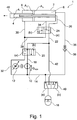
- the linear drive 1 has a hydraulic cylinder 2 which, as will be explained in more detail below, is designed with three pressure chambers 4, 6, 8.
- the pressure medium is supplied via a hydraulic machine 10, preferably a constant pump, which is driven by a variable-speed motor 12.
- a suction connection of the pump is connected via a low pressure line 14 to a low pressure source 16, for example a hydraulic accumulator or a tank.
- a pressure connection of the hydraulic machine 10 is connected to a pressure line 18, which leads to the single-port connection of a directional valve 20.
- this is designed as a 4/2-way switching valve, wherein in a basic position (a) shown, the pressure line 18 is connected to a supply line 22, which in turn leads to the input port of a control valve 24, which is also a 4/2-way Switch valve is executed.
- the third pressure chamber 8 is connected to a further output connection of the control valve 24 via a third working line 34, which is only shown for the purposes of the drawing.
- This working line 34 can also be combined with the suction line 36, which will be explained below.
- this third working line 34 to the supply line 22, the regeneration line 28 and the working line 26 is shut off.
- the control valve 24 into position (b) the third working line 34 is connected to the working line 26 and the supply line 22.
- the third pressure chamber 8 is additionally connected to the low pressure line 14 via a suction line 36 with a check valve 38 which is open towards the third pressure chamber 8.
- a storage valve 40 which is designed as a 3/2-way switching valve in the exemplary embodiment.
- the low-pressure source 16 In its basic position (a) shown, the low-pressure source 16 is connected to the low-pressure line 14.
- the low-pressure source 16 By switching over the storage valve 40, the low-pressure source 16 is connected to a line 42 leading into the supply line 22 and the connection to the low-pressure line 14 is blocked.
- the line 42 is shut off in the position (a) of the storage valve 40 to the low pressure source 16.
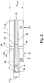
- the hydraulic cylinder 2 is designed with a piston 44 which has a hollow piston rod 46 into which a rod 50 supported on the cylinder base 48 dips so that an inner end face 52 of the hollow piston rod 46 and the end face of the rod 50 delimit the first pressure chamber 4. Its pressure supply takes place via a channel 54 which extends through the rod 50 and is connected to the working line 26.
- a piston rod-side ring end face 56 of the piston 54 delimits in the axial direction the second pressure chamber 6, through which the hollow piston rod 46 passes, and another rod-side ring end surface 58 delimits the third pressure chamber 8, through which the rod 50 passes.
- the active surfaces of these pressure chambers are shown in Figure 2 marked with the designations A1, A2, A3.
- the pressure chamber 6 is as based on Figure 1 explained, connected to the further working line 30 and the pressure chamber 8 to the third working line 34 and 36.
- the pressure medium volume flows Q 1 , Q 2 , Q 3 to the pressure chambers 4, 6 and 8 are also shown, which can be set by suitable control of the hydraulic machine 10.
- the hydraulic machine In order to set a rapid extension movement of the hollow piston rod 46 at high speed or high acceleration, the hydraulic machine is to promote a volume flow Q P with a predetermined pressure, which is to act on a comparatively small area of the hydraulic cylinder 2 which is effective in the extension direction, so that it has a comparatively low volume flow - and the associated low drive power - a high extension speed of the hydraulic cylinder 2 can be effected.
- the directional valve 20 and the control valve 24 are brought into their positions marked with (a).
- the storage valve 40 is also switched to position (a), so that pressure medium is drawn in from the low pressure source 16 via the hydraulic machine 10 and is conveyed into the first pressure chamber 4 via the supply line 22, the working line 26 and the channel 54.
- the regeneration line 28 is connected to the working line 26, so that the two pressure chambers 4, 6 are also connected to one another.
- the third pressure chamber 8 is in rapid traverse via the suction line 36 and the check valve 48 opening towards the pressure chamber 8 with the Low pressure line 14 and thus connected to the low pressure source 16.
- a pressure medium volume flow is supplied to the pressure chamber 4 with the active area A 1 via the hydraulic machine 10, so that the hollow piston rod 46 extends in the direction of the arrow.
- the pressure medium is pushed out of the shrinking second pressure chamber 6 and added via the regeneration line 28 to the pressure medium volume flow Q P conveyed by the hydraulic machine 10.
- the third pressure chamber 8 increases, so that pressure medium is sucked in from the low-pressure source 16 via the check valve 48.
- the hollow piston rod 46 thus extends at a comparatively high speed with a relatively low pressure medium volume flow.
- the volume flows Q 1 , Q 2 are calculated from the product of the extension speed x with the respective effective area A 1 , A 2 .
- the hollow piston rod 46 is extended at a comparatively low speed and great force.
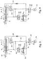
- the hydraulic machine 10 must be in accordance with Figure 3 Promote a pressure medium volume Q p force to the largest possible effective area in order to generate the desired large force.
- the control valve 24 and the control valve 20 switched into their switching positions (b).
- the storage valve 40 remains in position (a). Accordingly, the first pressure chamber 4 with a comparatively large effective area A 1 is supplied with pressure medium.
- the effective area A 3 of the third pressure chamber 8 acting in the same direction is also acted upon by the pressure of the hydraulic machine 10.
- the effective area A 2 of the second pressure chamber 6 acting in the opposite direction is connected via the further working line 30, the directional control valve 20 and the return line 32 to the low-pressure line 14 and thus to the suction side of the hydraulic machine 10 - the hollow piston rod 46 is subjected to great force at low speed x extended.
- the active surfaces A 1 , A 2 , A 3 are designed and interconnectable in such a way that the motor 12 operates at approximately the same speed or with approximately the same torque, both in the power stroke and in the rapid traverse (back and forth), the desired traversing speed x or force (px A) is then achieved by suitable interconnection.
- FIG. 5 shows the linear drive during the power stroke - exactly as in the exemplary embodiment described above, the directional valve 20 and the control valve 24 are adjusted to their switching positions (a), so that the active surfaces A 1 , A 3 are acted upon by the pressure at the outlet of the hydraulic machine 10.
- the second pressure chamber 6 is connected to the low pressure source 16 via the further working line 30, the directional control valve 20, the return line 32 and the low pressure line 14, so that the pressure medium can be pushed out of the third pressure chamber 6.
- the directional valve 20 and the control valve 24 are in accordance with Figure 6 adjusted to their positions (b).
- the first pressure chamber 4 and the second pressure chamber 6 are connected to one another, so that the pressure medium ejected from the latter via the Regeneration line 28 is summed to the pressure medium volume flow flowing to the first pressure chamber 4.
- pressure medium is sucked in via the suction line 36 and the check valve 38 from the low pressure source into the increasing third pressure chamber 8.
- the directional valve 20 and the control valve 24 are adjusted into their positions (a) (not shown) and the direction of rotation of the hydraulic machine 10 is reversed (see Figure 4 ), so that the two pressure chambers 4, 8 are connected to the suction side of the hydraulic machine 10 and the hydraulic machine 10 conveys pressure medium into the second pressure chamber 6. The pressure medium that was previously removed is then fed to the low-pressure accumulator 16.
- a hydraulic linear drive with a hydraulic cylinder designed with three pressure chambers, the effective surfaces of which are coordinated with one another in such a way that in a rapid traverse and in a power stroke, a drive of a hydraulic machine supplying the hydraulic cylinder with pressure medium operates in approximately the same speed / torque range.
Landscapes
- Engineering & Computer Science (AREA)
- Physics & Mathematics (AREA)
- Fluid Mechanics (AREA)
- Mechanical Engineering (AREA)
- General Engineering & Computer Science (AREA)
- Fluid-Pressure Circuits (AREA)
- Supply Devices, Intensifiers, Converters, And Telemotors (AREA)
- Actuator (AREA)
Description
- Die Erfindung betrifft einen hydraulischen Linearantrieb gemäß dem Oberbegriff des Patentanspruchs 1.
- Derartige hydraulische Linearantriebe können beispielsweise zur Betätigung eines Pressstempels einer Presse verwendet werden, wobei über den Linearantrieb beispielsweise im Eilgang ein Presswerkzeug geschlossen und der eigentliche Pressvorgang dann mit vergleichsweise großer Kraft in einem sogenannten "Krafthub" durchgeführt wird. Nach dem Pressvorgang wird der Pressstempel dann wieder im Eilgang in Gegenrichtung in seine Grundposition zurückbewegt. Selbstverständlich sind derartige Linearantriebe auch bei anderen Anwendungen, beispielsweise Stanzen, Werkzeugmaschinen, in Fertigungsstraßen etc. einsetzbar.
- In der
US 5,522,212 ist ein Linearantrieb gezeigt, bei dem die Vorschubbewegung über einen Hydraulikzylinder mit drei Druckräumen gesteuert wird. Bei der bekannten Lösung sind diese Druckräume mit unterschiedlichen Wirkflächen ausgeführt, wobei für den mit vergleichsweise geringer Kraft ausgeführten Eilgang eine erste Wirkfläche über eine Verstellpumpe mit Druckmittel beaufschlagt wird. Eine in gleicher Richtung wirksame Wirkfläche eines dritten Druckraums ist mit dem Druck eines Hydrospeichers beaufschlagt, während eine in Gegenrichtung wirksame Wirkfläche eines zweiten Druckraums zu einem Tank hin entlastet ist. Die Druckmittelverbindung zu der Verstellpumpe, zum Hydrospeicher und zum Tank wird über eine Ventilanordnung gesteuert, wobei dann für den Krafthub die Wirkflächen des ersten und des dritten Druckraums mit dem Pumpendruck und die in Gegenrichtung wirksame Wirkfläche des zweiten Druckraums mit Tankdruck beaufschlagt ist, die Verbindung zum Hydrospeicher ist dann abgesperrt. Bei der bekannten Lösung ist in dem Hydrospeicher eine eigene Ladepumpe zugeordnet, so dass dieser stets auf ein vorbestimmtes Niveau geladen ist. - Eine derartige Lösung bedarf eines sehr großen vorrichtungstechnischen Aufwandes, da zum Einen zur Steuerung der Bewegungen des Hydrozylinders eine aufwendige Verstellpumpe erforderlich ist und zum Anderen eine weitere Pumpe zum Aufladen des Hydrospeichers vorgesehen werden muss.
- In der
DE 10 2008 039 011 A1 ist ein ähnlicher Linearantrieb mit einem mit drei Wirkflächen ausgeführten Hydraulikzylinder offenbart, dessen Druckräume zum Verstellen über zwei parallel geschaltete drehzahlvariable Pumpen und eine Ventilanordnung mit Druckmittel beaufschlagt sind. Die Ansteuerung der beiden Pumpen ist sowohl im Hinblick auf die Ansteuerung als auch im Hinblick auf die Investitionskosten sehr aufwendig. - Einen gattungsgemäßen Linearantrieb zeigt die Druckschrift
NL8105929 - Demgegenüber liegt der Erfindung die Aufgabe zugrunde, einen hydraulischen Linearantrieb zu schaffen, der einen vergleichsweise einfachen Aufbau hat und eine auch in energetischer Hinsicht optimierte Ansteuerung ermöglicht.
- Diese Aufgabe wird durch einen hydraulischen Linearantrieb mit den Merkmalen des Patentanspruchs 1 gelöst.
- Vorteilhafte Weiterbildungen der Erfindung sind Gegenstand der Unteransprüche.
- Erfindungsgemäß hat der hydraulische Linearantrieb einen Hydraulikzylinder, der mit drei von jeweils einer Wirkfläche begrenzten Druckräumen ausgeführt ist, wobei diese über eine Hydromaschine, vorzugsweise eine Pumpe und eine Ventilanordnung mit Hochdruck (Pumpe) oder einer Niederdruckquelle, beispielsweise mit Tankdruck beaufschlagbar sind, um den Hydraulikzylinder im Eilgang oder in einem Krafthub in einer Richtung und im Eilgang oder im Krafthub in der anderen Richtung zu bewegen. Erfindungsgemäß ist der Hydromotor mit einem drehzahlvariablen Antrieb ausgeführt, wobei die Flächenverhältnisse der Wirkflächen so abgestimmt sind, dass im Eilgang und im Krafthub der Antrieb in etwa im gleichen Drehzahlbereich arbeitet.
- Durch diese Auslegung der Flächenverhältnisse und des Antriebs ist es möglich, letzteren jeweils im optimalen Drehmoment- und Drehzahlbereich und somit mit minimaler Antriebsleistung zu fahren, so dass der energetische Aufwand und der Investitionsaufwand gegenüber den eingangs genannten Lösungen deutlich verringert ist, da ein kleinerer Antriebsmotor verwendet werden kann. Im Wesentlichen unabhängig davon, ob der Hydraulikzylinder mit vergleichsweise großer Geschwindigkeit und kleiner Kraft (Eilgang) oder mit vergleichsweise geringer Geschwindigkeit und großer Kraft (Krafthub) betrieben wird, arbeitet der Antrieb stets in seinem optimalen Drehmoment-/Drehzahlbereich, so dass eine effektive Steuerung des Linearantriebs bei minimierter Antriebsleistung möglich ist. Ein weiterer Vorteil besteht darin, dass durch die konstante, vergleichsweise auf geringem Niveau vorbestimmte Drehzahl des Antriebs die Schallentwicklung des Linearantriebs in beiden Arbeitspunkten (Eilgang, Krafthub) minimal ist.
- Die Hydromaschine kann mit konstantem Förder-/Verdrängungsvolumen ausgeführt sein. Prinzipiell anwendbar sind jedoch auch für einen Vier-Quadrantenbetrieb ausgelegte Hydromaschinen, bei denen eine Drehrichtungsumkehr möglich ist.
- Erfindungsgemäß hat die Ventilanordnung ein Wegeventil, das in einer ersten Position einen Druckanschluss der Hydromaschine über eine Arbeitsleitung mit einem ersten Druckraum und einen zweiten Druckraum über eine weitere Arbeitsleitung mit der Niederdruckquelle, beispielsweise dem Tank verbindet. In einer weiteren, zweiten Position sperrt das Wegeventil eine Verbindung des zweiten Druckraums zur Niederdruckquelle ab.
- Erfindungsgemäß ist stromabwärts des Wegeventils ein Steuerventil angeordnet, das in einer Position den ersten Druckraum mit dem in Gegenrichtung wirksamen zweiten Druckraum verbindet.
- Erfindungsgemäß ist in der einen Position des Steuerventils eine Druckmittelverbindung des dritten Druckraums zur Hydromaschine gesperrt.
- Erfindungsgemäß ist der dritte Druckraum über eine Saugleitung mit einem in Richtung zum dritten Druckraum öffnenden Rückschlagventil mit der Niederdruckquelle/Tank verbunden sein.
- Bei einem Ausführungsbeispiel der Erfindung ist der Niederdruckquelle ein Speicherventil zugeordnet, das in einer Position die Niederdruckquelle mit einer Saugseite der Hydromaschine und in einer anderen Position die erstgenannte Arbeitsleitung im Bereich zwischen dem Wegeventil und dem Steuerventil mit der Niederdruckquelle verbindet.
- Vorzugsweise wird der erste Druckraum mit einer größeren Wirkfläche als der in Gegenrichtung wirksame zweite Druckraum ausgeführt.
- Dabei kann es vorteilhaft sein, wenn wiederum die zweite Wirkfläche etwas kleiner als die dritte Wirkfläche ausgelegt ist.
- Wie bereits erwähnt, kann es vorteilhaft sein, die Hydromaschine mit Drehrichtungsumkehr auszuführen, so dass ein Vier-Quadrantenbetrieb ermöglicht ist.
- Der hydraulische Linearantrieb lässt sich besonders vorteilhaft als Pressenantrieb oder als Schließachse einer Spritzgießmaschine ausführen. Prinzipiell kann das erfindungsgemäße Konzept überall da eingesetzt werden, wo Kraft und Geschwindigkeit zu unterschiedlichen Zeitpunkten benötigt wird.
- Bei einer Variante der Erfindung ist der Hydraulikzylinder mit einem Kolben mit einer Kolbenhohlstange ausgeführt, in den eine Stange des Hydraulikzylinders eintaucht, so dass durch diesen und eine Innenstirnfläche der Kolbenhohlstange der erste Druckraum begrenzt ist, der durch die Stange hindurch mit Druckmittel versorgt ist.
- Bei einem derartigen Ausführungsbeispiel wird es bevorzugt, wenn eine kolbenhohlstangenseitige Ringstirnfläche des Kolbens den zweiten Druckraum und eine davon abgewandte stangenseitige Ringstirnfläche den dritten Druckraum abschnittsweise begrenzt.
- Bevorzugte Ausführungsbeispiele der Erfindung werden im Folgenden anhand schematischer Zeichnungen näher erläutert. Es zeigen:
-
Figur 1 ein Schaltschema eines Ausführungsbeispiels eines hydraulischen Linerantriebs für eine Presse; -
Figur 2 eine Einzeldarstellung eines Hydraulikzylinders des Linearantriebs ausFigur 1 ; -
Figur 3 den Linearantrieb gemäßFigur 1 im Krafthub; -
Figur 4 den Linearantrieb gemäßFigur 1 bei einer Rückbewegung im Eilgang; -
Figur 5 ein gegenüber dem Ausführungsbeispiel gemäßFigur 1 vereinfachtes Ausführungsbeispiel eines Linearantriebs im Eilgang und -
Figur 6 den Linearantrieb gemäßFigur 5 im Krafthub - Der in
Figur 1 dargestellte Linearantrieb kann beispielsweise in der Stanz- oder Umformtechnik, beispielsweise bei Servopressen, Rohr- und Drahtbiegemaschinen, Abkantpressen, Stanz- und Nibbelmaschinen, Stanz- und Umformautomaten, Saugtransfer- oder Kompaktsaugerpressen, Reifenpressen, Reifenaufbaumaschinen, Vulkanisierpressen, Ziehpressen, Transfer- und Stufenpressen, Strangpressen, Biegezentren, Schmiedepressen, Schrottpressen, Spritzgießmaschinen, Blasformmaschinen oder Pulvermetallpressen verwendet werden. - Der Linearantrieb 1 hat einen Hydrozylinder 2, der, wie im Folgenden noch näher erläutert wird, mit drei Druckräumen 4, 6, 8 ausgeführt ist. Die Druckmittelversorgung erfolgt über eine Hydromaschine 10, vorzugsweise eine Konstantpumpe, die mit einem drehzahlvariablen Motor 12 angetrieben ist. Ein Sauganschluss der Pumpe ist über eine Niederdruckleitung 14 mit einer Niederdruckquelle 16, beispielsweise einem Hydrospeicher oder einem Tank verbunden. Ein Druckanschluss der Hydromaschine 10 ist an eine Druckleitung 18 angeschlossen, die zum Eingarigsanschluss eines Wegeventils 20 führt. Beim dargestellten Ausführungsbeispiel ist dieses als 4/2-Wege-Schaltventil ausgeführt, wobei in einer dargestellten Grundposition (a) die Druckleitung 18 an eine Versorgungsleitung 22 angeschlossen ist, die ihrerseits zum Eingangsanschluss eines Steuerventils 24 führt, das ebenfalls als 4/2-Wege-Schaltventil ausgeführt ist.
- In der dargestellten Grundposition (a) des Steuerventils 24 verbindet dies die Versorgungsleitung 22 mit einer Arbeitsleitung 26, über die der erste Druckraum 4 mit Druckmittel versorgt wird. In dieser Schaltposition ist ein weiterer Anschluss des Steuerventils 24 über eine Regenerationsleitung 28 mit einer weiteren Arbeitsleitung 30 verbunden, die einerseits mit einem Ausgangsanschluss des Wegeventils 20 und andererseits mit dem zweiten Druckraum 6 verbunden ist. In der Position (a) des Steuerventils 24 ist die Regenerationsleitung 28 mit der Arbeitsleitung 26 verbunden und in der Position (b) zum ersten Druckraum 4 hin abgesperrt. In der Grundposition (a) des Wegeventils 20 ist die Verbindung der Rücklaufleitung mit der weiteren Arbeitsleitung 30 abgesperrt. Das Wegeventil 20 hat einen Rücklaufanschluss, der über eine Rücklaufleitung 32 mit der Niederdruckleitung 14 verbunden ist. In der Schaltposition (a) des Wegeventils 20 ist die Druckmittelverbindung zwischen dieser Rücklaufleitung 32 und der weiteren Arbeitsleitung 30 unterbrochen. Durch Umschalten in die mit (b) gekennzeichnete Position wird diese Druckmittelverbindung geöffnet.
- Gemäß
Figur 1 ist der dritte Druckraum 8 über eine nur aus zeichnerischen Gründen dargestellte dritte Arbeitsleitung 34 mit einem weiteren Ausgangsanschluss des Steuerventils 24 verbunden. Diese Arbeitsleitung 34 kann auch mit der im Folgenden noch erläuterten Saugleitung 36 zusammengefasst sein. In der Schaltposition (a) des Steuerventils 24 ist diese dritte Arbeitsleitung 34 zu der Versorgungsleitung 22, der Regenerationsleitung 28 und zur Arbeitsleitung 26 hin abgesperrt. Durch Umschalten des Steuerventils 24 in die Position (b) wird die dritte Arbeitsleitung 34 mit der Arbeitsleitung 26 und der Versorgungsleitung 22 verbunden. - Gemäß
Figur 1 ist der dritte Druckraum 8 zusätzlich über eine Saugleitung 36 mit einem zum dritten Druckraum 8 hin geöffneten Rückschlagventil 38 mit der Niederdruckleitung 14 verbunden. - Diese ist an einem Ausgangsanschluss eines Speicherventils 40 angeschlossen, das in dem Ausführungsbeispiel als 3/2-Wegeschaltventil ausgeführt ist. In seiner dargestellten Grundposition (a) ist die Niederdruckquelle 16 mit der Niederdruckleitung 14 verbunden. Durch Umschalten des Speicherventils 40 wird die Niederdruckquelle 16 mit einer in die Versorgungsleitung 22 einmündenden Leitung 42 verbunden und die Verbindung zur Niederdruckleitung 14 gesperrt. Die Leitung 42 ist in der Position (a) des Speicherventils 40 zur Niederdruckquelle 16 hin abgesperrt.
- Einzelheiten des Hydraulikzylinders 2 werden anhand
Figur 2 erläutert. Demgemäß ist der Hydraulikzylinder 2 mit einem Kolben 44 ausgeführt, der eine Kolbenhohlstange 46 hat, in die eine am Zylinderboden 48 abgestützte Stange 50 eintaucht, so dass eine Innenstirnfläche 52 der Kolbenhohlstange 46 und die Stirnfläche der Stange 50 den ersten Druckraum 4 begrenzen. Dessen Druckversorgung erfolgt über einen sich durch die Stange 50 hindurch erstreckenden Kanal 54, der an die Arbeitsleitung 26 angeschlossen ist. Eine kolbenstangenseitige Ringstirnfläche 56 des Kolbens 54 begrenzt in Axialrichtung den zweiten, von der Kolbenhohlstange 46 durchsetzten Druckraum 6 und eine andere, stangenseitige Ringstirnfläche 58 begrenzt den von der Stange 50 durchsetzten dritten Druckraum 8. Die Wirkflächen dieser Druckräume sind inFigur 2 mit den Bezeichnungen A1, A2, A3 gekennzeichnet. Der Druckraum 6 ist, wie anhandFigur 1 erläutert, an die weitere Arbeitsleitung 30 und der Druckraum 8 an die dritte Arbeitsleitung 34 und 36 angeschlossen. In der Darstellung gemäßFigur 2 sind noch die Druckmittelvolumenströme Q1, Q2, Q3 zu den Druckräumen 4, 6 bzw. 8 dargestellt, die über geeignete Ansteuerung der Hydromaschine 10 einstellbar sind. - Zum Einstellen einer schnellen Ausfahrbewegung der Kolbenhohlstange 46 mit hoher Geschwindigkeit oder hoher Beschleunigung soll die Hydromaschine einen Volumenstrom QP mit einem vorbestimmten Druck fördern, der auf eine vergleichsweise kleine, in Ausfahrrichtung wirksame Fläche des Hydraulikzylinders 2 wirken soll, so dass mit einem vergleichsweise geringen Volumenstrom - und damit einhergehender geringer Antriebsleistung - eine hohe Ausfahrgeschwindigkeit des Hydraulikzylinders 2 bewirkt werden kann.
- Zur Einstellung des Eilganges werden das Wegeventil 20 und das Steuerventil 24 in ihre mit (a) gekennzeichneten Positionen gebracht. Das Speicherventil 40 ist ebenfalls in die Position (a) geschaltet, so dass aus der Niederdruckquelle 16 über die Hydromaschine 10 Druckmittel angesaugt und über die Versorgungsleitung 22, die Arbeitsleitung 26 und den Kanal 54 in den ersten Druckraum 4 gefördert wird. In der Position (a) des Steuerventils 24 ist die Regenerationsleitung 28 mit der Arbeitsleitung 26 verbunden, so dass auch die beiden Druckräume 4, 6 miteinander verbunden sind. Der dritte Druckraum 8 ist im Eilgang über die Saugleitung 36 und das sich zum Druckraum 8 hin öffnende Rückschlagventil 48 mit der Niederdruckleitung 14 und damit mit der Niederdruckquelle 16 verbunden. Dem Druckraum 4 mit der Wirkfläche A1 wird ein Druckmittelvolumenstrom über die Hydromaschine 10 zugeführt, so dass die Kolbenhohlstange 46 in Pfeilrichtung ausfährt. Dabei wird das Druckmittel aus dem sich verkleinernden zweiten Druckraum 6 ausgeschoben und über die Regenerationsleitung 28 zu dem von der Hydromaschine 10 geförderten Druckmittelvolumenstrom QP summiert. Beim Ausfahren der Kolbenhohlstange 46 im Eilgang vergrößert sich der dritte Druckraum 8, so dass Druckmittel über das Rückschlagventil 48 aus der Niederdruckquelle 16 nachgesaugt wird. Die Kolbenhohlstange 46 fährt somit mit vergleichsweise hoher Geschwindigkeit bei einem relativ niedrigen Druckmittelvolumenstrom aus. Bei dem dargestellten Ausführungsbeispiel ist die Wirkfläche A1 des ersten Druckraums 4 etwas größer als die Wirkfläche A2 des zweiten Druckraums ausgeführt, so dass zum Ausfahren der Kolbenhohlstange 46 lediglich ein geringer Druckmittelvolumenstrom Qp zum Pendelvolumenstrom (aus dem zweiten Druckraum 6.ausgeschobene Menge) hinzugefügt werden muss. Dementsprechend berechnet sich der von der Hydromaschine 10 zu fördernde Druckmittelvolumenstrom Qp aus der Formel

- Die Volumenströme Q1, Q2 berechnen sich aus dem Produkt der Ausfahrgeschwindigkeit x mit der jeweiligen Wirkfläche A1, A2. Der Fördervolumenstrom Qp der Hydromaschine kann berechnet werden aus dem Produkt der Drehzahl n des Antriebs 12 mit dem Förder-/Schluckvolumen V der Hydromaschine 10, so dass sich der Druckmittelvolumenstrom Qp, EIL im Eilgang nach den Gleichungen:


- Für den Krafthub wird die Kolbenhohlstange 46 mit vergleichsweise geringer Geschwindigkeit und großer Kraft ausgefahren. Hierzu muss die Hydromaschine 10 gemäß
Figur 3 einen Druckmittelvolumen Qp Kraft auf eine möglichst große Wirkfläche fördern, um die gewünschte große Kraft zu erzeugen. Hierzu werden gemäßFigur 3 das Steuerventil 24 und das Regelventil 20 in ihre Schaltpositionen (b) umgeschaltet. Das Speicherventil 40 verbleibt in der Position (a). Dementsprechend wird der erste Druckraum 4 mit vergleichsweise großer Wirkfläche A1 mit Druckmittel versorgt. Die in gleicher Richtung wirkende Wirkfläche A3 des dritten Druckraums 8 wird ebenfalls mit dem Druck der Hydromaschine 10 beaufschlagt. Die in Gegenrichtung wirkende Wirkfläche A2 des zweiten Druckraums 6 ist über die weitere Arbeitsleitung 30, das Wegeventil 20 und die Rücklaufleitung 32 mit der Niederdruckleitung 14 und damit mit der Saugseite der Hydromaschine 10 verbunden - die Kolbenhohlstange 46 wird mit großer Kraft bei geringer Geschwindigkeit x ausgefahren. Entsprechend den vorstehend erläuterten Rechnungsgleichungen ergibt sich dann der erforderliche Druckmittelvolumenstrom Qp, Kraft nach der Gleichung
- Unter der Annahme, dass die Drehzahlen n im Eilgang und im Krafthub in etwa gleich sein sollen, muss dann der Faktor K der Flächenverhältnisse den reziproken Wert des Geschwindigkeitsverhältnisses entsprechen:

- Zum schnellen Zurückfahren (Eilgang zurück) wird entsprechend gemäß der Darstellung in
Figur 4 die Drehrichtung des Motors 12 umgekehrt. Das Wegeventil 20 und das Steuerventil 24 verbleiben jeweils in ihrer Schaltposition (b), so dass die Hydromaschine 10 den Druckmittelvolumenstrom Qp, Eil in den in Einfahrrichtung wirkenden zweiten Druckraum 6 fördert. Die beiden in Gegenrichtung wirkenden Druckräume 4, 8 sind über das Wegeventil 20 und das Steuerventil 24 sowie das in seine Schaltposition (b) umgeschaltete Speicherventil 40 mit der Niederdruckquelle 16 verbunden, so dass das Druckmittel aus diesen Druckräumen 4, 8 zur Niederdruckquelle 16 oder zur Saugseite der Hydromaschine 10 hin abströmen kann - der Hydraulikzylinder 2 wird mit großer Geschwindigkeit und geringer Kraft eingefahren. - Gemäß den obigen Ausführungen sind die Wirkflächen A1, A2, A3 derart ausgelegt und miteinander verschaltbar, dass der Motor 12 sowohl im Krafthub als auch im Eilgang (vor und zurück) mit in etwa gleicher Drehzahl oder mit im etwa gleichem Drehmoment arbeitet, wobei dann durch geeignete Verschaltung die gewünschte Verfahrgeschwindigkeit x oder Kraft (p x A) erzielt wird.
- An Hand der
Figuren 5 und 6 wird eine zweite, gegenüber dem vorher beschriebenen Ausführungsbeispiel vereinfachte Variante erläutert. Der einzige wesentliche Unterschied besteht im Prinzip darin, dass bei dem in denFiguren 5 und 6 dargestellten Ausführungsbeispiel auf das Speicherventil 40 und die Leitung 42 verzichtet wird, so dass die Niederdruckleitung 14 direkt in die Niederdruckquelle 16 einmündet.Figur 5 zeigt den Linearantrieb beim Krafthub - genau wie beim zuvor beschriebenen Ausführungsbeispiel sind dabei das Wegeventil 20 und das Steuerventil 24 in ihre Schaltpositionen (a) verstellt, so dass die Wirkflächen A1, A3 mit dem Druck am Ausgang der Hydromaschine 10 beaufschlagt sind. Der zweite Druckraum 6 ist über die weitere Arbeitsleitung 30, das Wegeventil 20, die Rücklaufleitung 32 und die Niederdruckleitung 14 mit der Niederdruckquelle 16 verbunden, so dass das Druckmittel aus dem dritten Druckraum 6 ausgeschoben werden kann. - Für das Verfahren der Kolbenhohlstange 46 im Eilgang werden das Wegeventil 20 und das Steuerventil 24 gemäß
Figur 6 in ihre Positionen (b) verstellt. Dabei sind der erste Druckraum 4 und der zweite Druckraum 6 miteinander verbunden, so dass das aus letzterem ausgeschobene Druckmittel über die Regenerationsleitung 28 zu dem zum ersten Druckraum 4 strömenden Druckmittelvolumenstrom summiert wird. Während dieses Eilgangs wird Druckmittel über die Saugleitung 36 und das Rückschlagventil 38 aus der Niederdruckquelle in den sich vergrößernden dritten Druckraum 8 nachgesaugt. - Zum Einfahren der Kolbenhohlstange 46 im Eilgang werden das Wegeventil 20 und das Steuerventil 24 in ihre Positionen (a) verstellt (nicht dargestellt) und die Drehrichtung der Hydromaschine 10 umgekehrt (siehe
Figur 4 ), so dass die beiden Druckräume 4, 8 mit der Saugseite der Hydromaschine 10 verbunden sind und die Hydromaschine 10 Druckmittel in den zweiten Druckraum 6 fördert. Dem Niederdruckspeicher 16 wird dann das Druckmittel zugeführt, das zuvor entnommen wurde. - Im Übrigen entspricht das in den
Figuren 5 und 6 dargestellte Ausführungsbeispiel dem eingangs beschriebenen Ausführungsbeispiel, so dass weitere Erläuterungen entbehrlich sind. - Offenbart ist ein hydraulischer Linearantrieb mit einem mit drei Druckräumen ausgeführten Hydraulikzylinder, dessen Wirkflächen so aufeinander abgestimmt sind, dass in einem Eilgang und in einem Krafthub ein Antrieb einer den Hydraulikzylinder mit Druckmittel versorgenden Hydromaschine in etwa im gleichen Drehzahl-/Drehmomentbereich arbeitet.
-
- 1
- Linearantrieb
- 2
- Hydraulikzylinder
- 4
- Druckraum
- 6
- Druckraum
- 8
- Druckraum
- 10
- Hydromaschine
- 12
- Motor
- 14
- Niederdruckleitung
- 16
- Niederdruckquelle
- 18
- Druckleitung
- 20
- Wegeventil
- 22
- Versorgungsleitung
- 24
- Steuerventil
- 26
- Arbeitsleitung
- 28
- Regenerationsleitung
- 30
- weitere Arbeitsleitung
- 32
- Rücklaufleitung
- 34
- dritte Arbeitsleitung
- 36
- Saugleitung
- 38
- Rückschlagventil
- 40
- Speicherventil
- 42
- Leitung
- 44
- Kolben
- 46
- Kolbenhohlstange
- 48
- Zylinderboden
- 50
- Stange
- 52
- Innenstirnfläche
- 54
- Kanal
Claims (10)
- Hydraulischer Linearantrieb mit einem Hydraulikzylinder (2), der drei von jeweils einer Wirkfläche (A1, A2, A3) begrenzte Druckräume (4, 6, 8) aufweist, die über eine Hydromaschine (10) und eine Ventilanordnung des Linearantriebs mit Hochdruck oder Niederdruck beaufschlagbar sind, um den Hydrozylinder (2) im Eilgang oder im Krafthub in einer Richtung oder im Eilgang oder Krafthub in der anderen Richtung zu bewegen, wobei die Ventilanordnung ein Wegeventil (20) hat, das in einer ersten Position (b) einen Druckanschluss der Hydromaschine (10) über eine Arbeitsleitung (26) mit einem ersten (4) der Druckräume (4, 6, 8) und einen zweiten (6) der Druckräume (4, 6, 8) über eine weitere Arbeitsleitung (30) mit einer Niederdruckquelle (16) verbindet und in einer zweiten Position (a) die Verbindung des zweiten Druckraums (6) zur Niederdruckquelle (16) sperrt, wobei in Druckaufbaurichtung stromabwärts des Wegeventils (20) ein Steuerventil (24) angeordnet ist, das in einer Position (a) den ersten Druckraum (4) mit dem in Gegenrichtung wirksamen zweiten Druckraum (6) und in der anderen Position (b) den ersten Druckraum mit dem dritten Druckraum (8) verbindet, und wobei in der einen Position (a) des Steuerventils (24) eine Druckmittelverbindung des dritten Druckraums (8) zur Hydromaschine (10) gesperrt ist, dadurch gekennzeichnet, dass die Hydromaschine (10) einen drehzahlvariablen Antrieb (12) hat und dass die Flächenverhältnisse der Wirkflächen (A1, A2, A3) so abgestimmt sind, dass im Eilgang und im Krafthub der Antrieb (12) im gleichen Drehzahlbereich arbeitet, und dass der dritte Druckraum (8) über eine Saugleitung (36) und ein in Richtung des dritten Druckraums (8) öffnendes Rückschlagventil (38) mit der Niederdruckquelle (16) verbunden ist.
- Hydraulischer Linearantrieb mit einem Hydraulikzylinder (2), der drei von jeweils einer Wirkfläche (A1, A2, A3) begrenzte Druckräume (4, 6, 8) aufweist, die über eine Hydromaschine (10) und eine Ventilanordnung des Linearantriebs mit Hochdruck oder Niederdruck beaufschlagbar sind, um den Hydrozylinder (2) im Eilgang oder im Krafthub in einer Richtung oder im Eilgang oder Krafthub in der anderen Richtung zu bewegen, wobei die Ventilanordnung ein Wegeventil (20) hat, das in einer ersten Position (b) einen Druckanschluss der Hydromaschine (10) über eine Arbeitsleitung (26) mit einem ersten (4) der Druckräume (4, 6, 8) und einen zweiten (6) der Druckräume (4, 6, 8) über eine weitere Arbeitsleitung (30) mit einer Niederdruckquelle (16) verbindet und in einer zweiten Position (a) die Verbindung des zweiten Druckraums (6) zur Niederdruckquelle (16) sperrt, wobei in Druckaufbaurichtung stromabwärts des Wegeventils (20) ein Steuerventil (24) angeordnet ist, das in einer Position (a) den ersten Druckraum (4) mit dem in Gegenrichtung wirksamen zweiten Druckraum (6) und in der anderen Position (b) den ersten Druckraum mit dem dritten Druckraum (8) verbindet, und wobei in der einen Position (a) des Steuerventils (24) eine Druckmittelverbindung des dritten Druckraums (8) zur Hydromaschine (10) gesperrt ist, dadurch gekennzeichnet, dass die Hydromaschine (10) einen drehzahlvariablen Antrieb (12) hat und dass die Flächenverhältnisse der Wirkflächen (A1, A2, A3) so abgestimmt sind, dass im Eilgang und im Krafthub der Antrieb (12) im gleichen Drehzahlbereich arbeitet, und dass der dritte Druckraum (8) über eine Saugleitung (36) und ein in Richtung des dritten Druckraums (8) öffnendes Rückschlagventil (38) mit einer Niederdruckseite der Hydromaschine (10) verbunden ist und dass ein Speicherventil (40) des Linearantriebs vorgesehen ist, das in einer Position (a) die Niederdruckquelle (16) mit der Niederdruckseite der Hydromaschine (10) und in der anderen Position (b) die Niederdruckquelle (16) mit einer Versorgungsleitung (22) zwischen dem Wegeventil (20) und dem Steuerventil (24) verbindet.
- Linearantrieb nach Patentanspruch 1 oder 2, wobei die Hydromaschine (10) eine Maschine mit konstantem Förder- / Schluckvolumen ist.
- Linearantrieb nach Anspruch 1 oder Anspruch 3 in Kombination mit Anspruch 1, mit einem Speicherventil (40), das in einer Position (a) die Niederdruckquelle (16) mit einer Niederdruckseite der Hydromaschine (10) und in der anderen Position (b) die Niederdruckquelle (16) mit einer Versorgungsleitung (22) zwischen dem Wegeventil (20) und dem Steuerventil (24) verbindet.
- Linearantrieb nach einem der vorhergehenden Patentansprüche, wobei der erste Druckraum (4) eine größere Wirkfläche (A1) als der in Gegenrichtung wirksame zweite Druckraum (6) hat.
- Linearantrieb nach Patentanspruch 5, wobei die Wirkfläche (A2) des zweiten Druckraums (6) etwas kleiner als die Wirkfläche (A3) des dritten Druckraums (8) ist.
- Linearantrieb nach einem der vorhergehenden Patentansprüche, wobei der drehzahlvariable Antrieb in Gestalt eines Motors (12) oder die Hydromaschine (10) mit Drehrichtungsumkehr ausgeführt ist.
- Linearantrieb nach einem der vorhergehenden Patentansprüche, wobei dieser als ein Antrieb einer Umformmaschine oder Spritz- / Blasformmaschine verwendbar ist.
- Linearantrieb nach einem der vorhergehenden Patentansprüche, wobei der Hydraulikzylinder (2) einen Kolben (44) mit einer Kolbenhohlstange (46) hat, in die eine Stange (50) des Hydraulikzylinders (2) eintaucht, so dass durch eine Innenstirnfläche (52) der Kolbenhohlstange (46) und die Stirnfläche der Stange (50) der erste Druckraum (4) axial begrenzt ist, der durch die Stange (50) hindurch mit Druckmittel versorgt ist.
- Linearantrieb nach Patentanspruch 9, wobei eine kolbenstangenseitige Ringstirnfläche (A2) des Kolbens (44) den zweiten Druckraum (6) und eine davon abgewandte stangenseitige Ringstirnfläche (A3) des Kolbens (44) den dritten Druckraum (8) in Axialrichtung begrenzt.
Applications Claiming Priority (1)
| Application Number | Priority Date | Filing Date | Title |
|---|---|---|---|
| DE102010034610A DE102010034610A1 (de) | 2010-08-18 | 2010-08-18 | Hydraulischer Linearantrieb |
Publications (3)
| Publication Number | Publication Date |
|---|---|
| EP2420681A2 EP2420681A2 (de) | 2012-02-22 |
| EP2420681A3 EP2420681A3 (de) | 2014-09-24 |
| EP2420681B1 true EP2420681B1 (de) | 2020-01-08 |
Family
ID=44650824
Family Applications (1)
| Application Number | Title | Priority Date | Filing Date |
|---|---|---|---|
| EP11006709.7A Active EP2420681B1 (de) | 2010-08-18 | 2011-08-17 | Hydraulischer Linearantrieb |
Country Status (2)
| Country | Link |
|---|---|
| EP (1) | EP2420681B1 (de) |
| DE (1) | DE102010034610A1 (de) |
Families Citing this family (9)
| Publication number | Priority date | Publication date | Assignee | Title |
|---|---|---|---|---|
| JP6479306B2 (ja) * | 2013-08-05 | 2019-03-06 | 住友重機械工業株式会社 | ショベル |
| JP6385654B2 (ja) * | 2013-08-05 | 2018-09-05 | 住友重機械工業株式会社 | ショベル |
| EP3032112B1 (de) * | 2013-08-05 | 2017-11-22 | Sumitomo Heavy Industries, Ltd. | Schaufel |
| WO2016008151A1 (en) * | 2014-07-18 | 2016-01-21 | Norgren, Inc. | Stretch blow molding cylinder and related method |
| DE102015211796A1 (de) * | 2015-06-25 | 2016-12-29 | Robert Bosch Gmbh | Hydraulisches System zur Druckmittelversorgung eines Hydrozylinders mit drei getrennten druckmittelbeaufschlagbaren Wirkflächen und Verfahren zum Betreiben des hydraulischen Systems |
| DE102016214767A1 (de) * | 2016-02-16 | 2017-08-17 | Sms Group Gmbh | Gleichgangzylinder für Strangpressanlagen |
| CN107243774B (zh) * | 2017-05-19 | 2019-11-08 | 深圳市睿格晟设备有限公司 | 一种改良吸屑机 |
| DE102018203367A1 (de) | 2018-03-07 | 2019-09-12 | Robert Bosch Gmbh | Hydrostatischer Linearantrieb |
| DE102019105449A1 (de) * | 2019-03-04 | 2020-09-10 | Wacker Neuson Linz Gmbh | Linearantrieb mit geschlossenem Hydraulikkreislauf |
Family Cites Families (4)
| Publication number | Priority date | Publication date | Assignee | Title |
|---|---|---|---|---|
| NL8105929A (nl) * | 1981-12-31 | 1983-07-18 | Hydraudyne Bv | Zuiger/cilinder eenheid. |
| US5522212A (en) | 1994-12-21 | 1996-06-04 | Kubik; Philip A. | Rod equal displacement cylinder in a rapid transfer and feed system |
| DE102004027849A1 (de) * | 2004-06-08 | 2006-01-05 | Bosch Rexroth Aktiengesellschaft | Antriebseinheit |
| DE102008039011B4 (de) | 2008-08-21 | 2020-01-16 | MAE Maschinen- u. Apparatebau Götzen GmbH | Druckspeicherlose hydraulische Antriebsanordnung sowie Verfahren zum druckspeicherlosen hydraulischen Antreiben eines Verbrauchers |
-
2010
- 2010-08-18 DE DE102010034610A patent/DE102010034610A1/de not_active Ceased
-
2011
- 2011-08-17 EP EP11006709.7A patent/EP2420681B1/de active Active
Non-Patent Citations (1)
| Title |
|---|
| None * |
Also Published As
| Publication number | Publication date |
|---|---|
| EP2420681A2 (de) | 2012-02-22 |
| EP2420681A3 (de) | 2014-09-24 |
| DE102010034610A1 (de) | 2012-02-23 |
Similar Documents
| Publication | Publication Date | Title |
|---|---|---|
| EP2480405B1 (de) | Vorgespannter hydraulischer antrieb mit drehzahlvariabler pumpe | |
| EP2420681A2 (de) | Hydraulischer Linearantrieb | |
| DE102011000473B4 (de) | Pressmaschine und Verfahren zum Pressen von Werkstücken | |
| EP2722165B1 (de) | Hydraulische schaltung für eine hydraulische achse und eine hydraulische achse | |
| EP2732959A2 (de) | Druckspeicherlose hydraulische Antriebsanordnung für und mit einem Verbraucher, Insbesondere für hydraulische Pressen, sowie Verfahren zum druckspeicherlosen hydraulischen Antreiben eines Verbrauchers | |
| EP3880975B1 (de) | Elektrohydrostatisches aktuatorsystem | |
| EP2267317A2 (de) | Hydrauliksystem | |
| EP3077674B1 (de) | Hydraulische anordnung | |
| DE102009040126A1 (de) | Elektromotorischer Hydraulikantrieb und Verfahren zum Bereitstellen eines definierten Hydraulikdrucks und/oder -volumens | |
| EP1656224B1 (de) | Einrichtung zur steuerung des ziehvorgangs bei einer transferpresse | |
| EP1706648B1 (de) | Antriebsvorrichtung | |
| EP1181458B1 (de) | Hydraulischer antrieb mit mehreren auch einen differentialzylinder umfassenden hydraulischen verbrauchern | |
| WO2023041476A1 (de) | Hydraulisches antriebssystem mit einer 4q pumpeneinheit | |
| DE102012009182A1 (de) | Hydraulische Strangpresse sowie Verfahren zum Betrieb einer hydraulischen Strangpresse | |
| DE102013007148B4 (de) | Hydraulischer Pressantrieb mit Energierückspeisung | |
| DE10239591B4 (de) | Einzelmotoreinspritz- und Schraubenantriebshybridaktuator | |
| DE102017000523B4 (de) | Hydraulikvorrichtung für eine Formgebungsmaschine | |
| WO2002076703A2 (de) | Elektromechanische spannvorrichtung | |
| EP2229537B1 (de) | Hydraulische antriebsvorrichtung mit zwei druckräumen und verfahren zum betreiben einer hydraulischen antriebsvorrichtung mit zwei druckräumen | |
| DE102018203367A1 (de) | Hydrostatischer Linearantrieb | |
| EP0751842B1 (de) | Doppelpresse | |
| DE102010024246A1 (de) | Verfahren und Vorrichtung zum Betrieb einer angetriebenen Achse bei einer Werkzeugmaschine | |
| DE102015222672A1 (de) | Verfahren zum Betreiben einer elektro-hydraulischen Achse und elektro-hydraulische Achse | |
| DE10104109A1 (de) | Regelverfahren für die hydraulische Unterstützung eines elektrischen Antriebs | |
| EP2549123A2 (de) | Hydropneumatisches Antriebssystem mit einem oder mehreren Doppelmediumarbeitszylindern |
Legal Events
| Date | Code | Title | Description |
|---|---|---|---|
| AK | Designated contracting states |
Kind code of ref document: A2 Designated state(s): AL AT BE BG CH CY CZ DE DK EE ES FI FR GB GR HR HU IE IS IT LI LT LU LV MC MK MT NL NO PL PT RO RS SE SI SK SM TR |
|
| AX | Request for extension of the european patent |
Extension state: BA ME |
|
| PUAI | Public reference made under article 153(3) epc to a published international application that has entered the european phase |
Free format text: ORIGINAL CODE: 0009012 |
|
| RIN1 | Information on inventor provided before grant (corrected) |
Inventor name: BECKMANN, BASTIAN |
|
| PUAL | Search report despatched |
Free format text: ORIGINAL CODE: 0009013 |
|
| AK | Designated contracting states |
Kind code of ref document: A3 Designated state(s): AL AT BE BG CH CY CZ DE DK EE ES FI FR GB GR HR HU IE IS IT LI LT LU LV MC MK MT NL NO PL PT RO RS SE SI SK SM TR |
|
| AX | Request for extension of the european patent |
Extension state: BA ME |
|
| RIC1 | Information provided on ipc code assigned before grant |
Ipc: F15B 11/024 20060101AFI20140815BHEP Ipc: F15B 11/036 20060101ALI20140815BHEP |
|
| 17P | Request for examination filed |
Effective date: 20150324 |
|
| RBV | Designated contracting states (corrected) |
Designated state(s): AL AT BE BG CH CY CZ DE DK EE ES FI FR GB GR HR HU IE IS IT LI LT LU LV MC MK MT NL NO PL PT RO RS SE SI SK SM TR |
|
| STAA | Information on the status of an ep patent application or granted ep patent |
Free format text: STATUS: EXAMINATION IS IN PROGRESS |
|
| 17Q | First examination report despatched |
Effective date: 20180703 |
|
| GRAP | Despatch of communication of intention to grant a patent |
Free format text: ORIGINAL CODE: EPIDOSNIGR1 |
|
| STAA | Information on the status of an ep patent application or granted ep patent |
Free format text: STATUS: GRANT OF PATENT IS INTENDED |
|
| INTG | Intention to grant announced |
Effective date: 20191018 |
|
| GRAS | Grant fee paid |
Free format text: ORIGINAL CODE: EPIDOSNIGR3 |
|
| GRAA | (expected) grant |
Free format text: ORIGINAL CODE: 0009210 |
|
| STAA | Information on the status of an ep patent application or granted ep patent |
Free format text: STATUS: THE PATENT HAS BEEN GRANTED |
|
| AK | Designated contracting states |
Kind code of ref document: B1 Designated state(s): AL AT BE BG CH CY CZ DE DK EE ES FI FR GB GR HR HU IE IS IT LI LT LU LV MC MK MT NL NO PL PT RO RS SE SI SK SM TR |
|
| REG | Reference to a national code |
Ref country code: GB Ref legal event code: FG4D Free format text: NOT ENGLISH |
|
| REG | Reference to a national code |
Ref country code: CH Ref legal event code: EP |
|
| REG | Reference to a national code |
Ref country code: DE Ref legal event code: R096 Ref document number: 502011016370 Country of ref document: DE |
|
| REG | Reference to a national code |
Ref country code: IE Ref legal event code: FG4D Free format text: LANGUAGE OF EP DOCUMENT: GERMAN |
|
| REG | Reference to a national code |
Ref country code: AT Ref legal event code: REF Ref document number: 1223079 Country of ref document: AT Kind code of ref document: T Effective date: 20200215 |
|
| RAP2 | Party data changed (patent owner data changed or rights of a patent transferred) |
Owner name: ROBERT BOSCH GMBH |
|
| REG | Reference to a national code |
Ref country code: NL Ref legal event code: MP Effective date: 20200108 |
|
| REG | Reference to a national code |
Ref country code: LT Ref legal event code: MG4D |
|
| PG25 | Lapsed in a contracting state [announced via postgrant information from national office to epo] |
Ref country code: LT Free format text: LAPSE BECAUSE OF FAILURE TO SUBMIT A TRANSLATION OF THE DESCRIPTION OR TO PAY THE FEE WITHIN THE PRESCRIBED TIME-LIMIT Effective date: 20200108 Ref country code: NL Free format text: LAPSE BECAUSE OF FAILURE TO SUBMIT A TRANSLATION OF THE DESCRIPTION OR TO PAY THE FEE WITHIN THE PRESCRIBED TIME-LIMIT Effective date: 20200108 Ref country code: NO Free format text: LAPSE BECAUSE OF FAILURE TO SUBMIT A TRANSLATION OF THE DESCRIPTION OR TO PAY THE FEE WITHIN THE PRESCRIBED TIME-LIMIT Effective date: 20200408 Ref country code: FI Free format text: LAPSE BECAUSE OF FAILURE TO SUBMIT A TRANSLATION OF THE DESCRIPTION OR TO PAY THE FEE WITHIN THE PRESCRIBED TIME-LIMIT Effective date: 20200108 Ref country code: PT Free format text: LAPSE BECAUSE OF FAILURE TO SUBMIT A TRANSLATION OF THE DESCRIPTION OR TO PAY THE FEE WITHIN THE PRESCRIBED TIME-LIMIT Effective date: 20200531 Ref country code: RS Free format text: LAPSE BECAUSE OF FAILURE TO SUBMIT A TRANSLATION OF THE DESCRIPTION OR TO PAY THE FEE WITHIN THE PRESCRIBED TIME-LIMIT Effective date: 20200108 |
|
| PG25 | Lapsed in a contracting state [announced via postgrant information from national office to epo] |
Ref country code: HR Free format text: LAPSE BECAUSE OF FAILURE TO SUBMIT A TRANSLATION OF THE DESCRIPTION OR TO PAY THE FEE WITHIN THE PRESCRIBED TIME-LIMIT Effective date: 20200108 Ref country code: LV Free format text: LAPSE BECAUSE OF FAILURE TO SUBMIT A TRANSLATION OF THE DESCRIPTION OR TO PAY THE FEE WITHIN THE PRESCRIBED TIME-LIMIT Effective date: 20200108 Ref country code: SE Free format text: LAPSE BECAUSE OF FAILURE TO SUBMIT A TRANSLATION OF THE DESCRIPTION OR TO PAY THE FEE WITHIN THE PRESCRIBED TIME-LIMIT Effective date: 20200108 Ref country code: BG Free format text: LAPSE BECAUSE OF FAILURE TO SUBMIT A TRANSLATION OF THE DESCRIPTION OR TO PAY THE FEE WITHIN THE PRESCRIBED TIME-LIMIT Effective date: 20200408 Ref country code: IS Free format text: LAPSE BECAUSE OF FAILURE TO SUBMIT A TRANSLATION OF THE DESCRIPTION OR TO PAY THE FEE WITHIN THE PRESCRIBED TIME-LIMIT Effective date: 20200508 Ref country code: GR Free format text: LAPSE BECAUSE OF FAILURE TO SUBMIT A TRANSLATION OF THE DESCRIPTION OR TO PAY THE FEE WITHIN THE PRESCRIBED TIME-LIMIT Effective date: 20200409 |
|
| REG | Reference to a national code |
Ref country code: DE Ref legal event code: R097 Ref document number: 502011016370 Country of ref document: DE |
|
| PG25 | Lapsed in a contracting state [announced via postgrant information from national office to epo] |
Ref country code: CZ Free format text: LAPSE BECAUSE OF FAILURE TO SUBMIT A TRANSLATION OF THE DESCRIPTION OR TO PAY THE FEE WITHIN THE PRESCRIBED TIME-LIMIT Effective date: 20200108 Ref country code: SK Free format text: LAPSE BECAUSE OF FAILURE TO SUBMIT A TRANSLATION OF THE DESCRIPTION OR TO PAY THE FEE WITHIN THE PRESCRIBED TIME-LIMIT Effective date: 20200108 Ref country code: DK Free format text: LAPSE BECAUSE OF FAILURE TO SUBMIT A TRANSLATION OF THE DESCRIPTION OR TO PAY THE FEE WITHIN THE PRESCRIBED TIME-LIMIT Effective date: 20200108 Ref country code: EE Free format text: LAPSE BECAUSE OF FAILURE TO SUBMIT A TRANSLATION OF THE DESCRIPTION OR TO PAY THE FEE WITHIN THE PRESCRIBED TIME-LIMIT Effective date: 20200108 Ref country code: SM Free format text: LAPSE BECAUSE OF FAILURE TO SUBMIT A TRANSLATION OF THE DESCRIPTION OR TO PAY THE FEE WITHIN THE PRESCRIBED TIME-LIMIT Effective date: 20200108 Ref country code: ES Free format text: LAPSE BECAUSE OF FAILURE TO SUBMIT A TRANSLATION OF THE DESCRIPTION OR TO PAY THE FEE WITHIN THE PRESCRIBED TIME-LIMIT Effective date: 20200108 Ref country code: RO Free format text: LAPSE BECAUSE OF FAILURE TO SUBMIT A TRANSLATION OF THE DESCRIPTION OR TO PAY THE FEE WITHIN THE PRESCRIBED TIME-LIMIT Effective date: 20200108 |
|
| PLBE | No opposition filed within time limit |
Free format text: ORIGINAL CODE: 0009261 |
|
| STAA | Information on the status of an ep patent application or granted ep patent |
Free format text: STATUS: NO OPPOSITION FILED WITHIN TIME LIMIT |
|
| 26N | No opposition filed |
Effective date: 20201009 |
|
| PG25 | Lapsed in a contracting state [announced via postgrant information from national office to epo] |
Ref country code: IT Free format text: LAPSE BECAUSE OF FAILURE TO SUBMIT A TRANSLATION OF THE DESCRIPTION OR TO PAY THE FEE WITHIN THE PRESCRIBED TIME-LIMIT Effective date: 20200108 |
|
| PG25 | Lapsed in a contracting state [announced via postgrant information from national office to epo] |
Ref country code: PL Free format text: LAPSE BECAUSE OF FAILURE TO SUBMIT A TRANSLATION OF THE DESCRIPTION OR TO PAY THE FEE WITHIN THE PRESCRIBED TIME-LIMIT Effective date: 20200108 Ref country code: SI Free format text: LAPSE BECAUSE OF FAILURE TO SUBMIT A TRANSLATION OF THE DESCRIPTION OR TO PAY THE FEE WITHIN THE PRESCRIBED TIME-LIMIT Effective date: 20200108 |
|
| PG25 | Lapsed in a contracting state [announced via postgrant information from national office to epo] |
Ref country code: MC Free format text: LAPSE BECAUSE OF FAILURE TO SUBMIT A TRANSLATION OF THE DESCRIPTION OR TO PAY THE FEE WITHIN THE PRESCRIBED TIME-LIMIT Effective date: 20200108 |
|
| REG | Reference to a national code |
Ref country code: CH Ref legal event code: PL |
|
| GBPC | Gb: european patent ceased through non-payment of renewal fee |
Effective date: 20200817 |
|
| PG25 | Lapsed in a contracting state [announced via postgrant information from national office to epo] |
Ref country code: CH Free format text: LAPSE BECAUSE OF NON-PAYMENT OF DUE FEES Effective date: 20200831 Ref country code: LI Free format text: LAPSE BECAUSE OF NON-PAYMENT OF DUE FEES Effective date: 20200831 Ref country code: LU Free format text: LAPSE BECAUSE OF NON-PAYMENT OF DUE FEES Effective date: 20200817 |
|
| REG | Reference to a national code |
Ref country code: BE Ref legal event code: MM Effective date: 20200831 |
|
| PG25 | Lapsed in a contracting state [announced via postgrant information from national office to epo] |
Ref country code: FR Free format text: LAPSE BECAUSE OF NON-PAYMENT OF DUE FEES Effective date: 20200831 |
|
| PG25 | Lapsed in a contracting state [announced via postgrant information from national office to epo] |
Ref country code: BE Free format text: LAPSE BECAUSE OF NON-PAYMENT OF DUE FEES Effective date: 20200831 Ref country code: IE Free format text: LAPSE BECAUSE OF NON-PAYMENT OF DUE FEES Effective date: 20200817 Ref country code: GB Free format text: LAPSE BECAUSE OF NON-PAYMENT OF DUE FEES Effective date: 20200817 |
|
| REG | Reference to a national code |
Ref country code: AT Ref legal event code: MM01 Ref document number: 1223079 Country of ref document: AT Kind code of ref document: T Effective date: 20200817 |
|
| PG25 | Lapsed in a contracting state [announced via postgrant information from national office to epo] |
Ref country code: AT Free format text: LAPSE BECAUSE OF NON-PAYMENT OF DUE FEES Effective date: 20200817 |
|
| PG25 | Lapsed in a contracting state [announced via postgrant information from national office to epo] |
Ref country code: TR Free format text: LAPSE BECAUSE OF FAILURE TO SUBMIT A TRANSLATION OF THE DESCRIPTION OR TO PAY THE FEE WITHIN THE PRESCRIBED TIME-LIMIT Effective date: 20200108 Ref country code: MT Free format text: LAPSE BECAUSE OF FAILURE TO SUBMIT A TRANSLATION OF THE DESCRIPTION OR TO PAY THE FEE WITHIN THE PRESCRIBED TIME-LIMIT Effective date: 20200108 Ref country code: CY Free format text: LAPSE BECAUSE OF FAILURE TO SUBMIT A TRANSLATION OF THE DESCRIPTION OR TO PAY THE FEE WITHIN THE PRESCRIBED TIME-LIMIT Effective date: 20200108 |
|
| PG25 | Lapsed in a contracting state [announced via postgrant information from national office to epo] |
Ref country code: MK Free format text: LAPSE BECAUSE OF FAILURE TO SUBMIT A TRANSLATION OF THE DESCRIPTION OR TO PAY THE FEE WITHIN THE PRESCRIBED TIME-LIMIT Effective date: 20200108 Ref country code: AL Free format text: LAPSE BECAUSE OF FAILURE TO SUBMIT A TRANSLATION OF THE DESCRIPTION OR TO PAY THE FEE WITHIN THE PRESCRIBED TIME-LIMIT Effective date: 20200108 |
|
| PGFP | Annual fee paid to national office [announced via postgrant information from national office to epo] |
Ref country code: DE Payment date: 20251021 Year of fee payment: 15 |