EP2420681B1 - Entraînement linéaire hydraulique - Google Patents
Entraînement linéaire hydraulique Download PDFInfo
- Publication number
- EP2420681B1 EP2420681B1 EP11006709.7A EP11006709A EP2420681B1 EP 2420681 B1 EP2420681 B1 EP 2420681B1 EP 11006709 A EP11006709 A EP 11006709A EP 2420681 B1 EP2420681 B1 EP 2420681B1
- Authority
- EP
- European Patent Office
- Prior art keywords
- pressure
- linear drive
- pressure space
- valve
- hydraulic
- Prior art date
- Legal status (The legal status is an assumption and is not a legal conclusion. Google has not performed a legal analysis and makes no representation as to the accuracy of the status listed.)
- Active
Links
Images

Classifications
-
- F—MECHANICAL ENGINEERING; LIGHTING; HEATING; WEAPONS; BLASTING
- F15—FLUID-PRESSURE ACTUATORS; HYDRAULICS OR PNEUMATICS IN GENERAL
- F15B—SYSTEMS ACTING BY MEANS OF FLUIDS IN GENERAL; FLUID-PRESSURE ACTUATORS, e.g. SERVOMOTORS; DETAILS OF FLUID-PRESSURE SYSTEMS, NOT OTHERWISE PROVIDED FOR
- F15B11/00—Servomotor systems without provision for follow-up action; Circuits therefor
- F15B11/02—Systems essentially incorporating special features for controlling the speed or actuating force of an output member
- F15B11/028—Systems essentially incorporating special features for controlling the speed or actuating force of an output member for controlling the actuating force
- F15B11/036—Systems essentially incorporating special features for controlling the speed or actuating force of an output member for controlling the actuating force by means of servomotors having a plurality of working chambers
-
- F—MECHANICAL ENGINEERING; LIGHTING; HEATING; WEAPONS; BLASTING
- F15—FLUID-PRESSURE ACTUATORS; HYDRAULICS OR PNEUMATICS IN GENERAL
- F15B—SYSTEMS ACTING BY MEANS OF FLUIDS IN GENERAL; FLUID-PRESSURE ACTUATORS, e.g. SERVOMOTORS; DETAILS OF FLUID-PRESSURE SYSTEMS, NOT OTHERWISE PROVIDED FOR
- F15B11/00—Servomotor systems without provision for follow-up action; Circuits therefor
- F15B11/02—Systems essentially incorporating special features for controlling the speed or actuating force of an output member
- F15B11/024—Systems essentially incorporating special features for controlling the speed or actuating force of an output member by means of differential connection of the servomotor lines, e.g. regenerative circuits
-
- F—MECHANICAL ENGINEERING; LIGHTING; HEATING; WEAPONS; BLASTING
- F15—FLUID-PRESSURE ACTUATORS; HYDRAULICS OR PNEUMATICS IN GENERAL
- F15B—SYSTEMS ACTING BY MEANS OF FLUIDS IN GENERAL; FLUID-PRESSURE ACTUATORS, e.g. SERVOMOTORS; DETAILS OF FLUID-PRESSURE SYSTEMS, NOT OTHERWISE PROVIDED FOR
- F15B2211/00—Circuits for servomotor systems
- F15B2211/20—Fluid pressure source, e.g. accumulator or variable axial piston pump
- F15B2211/205—Systems with pumps
- F15B2211/20507—Type of prime mover
- F15B2211/20515—Electric motor
-
- F—MECHANICAL ENGINEERING; LIGHTING; HEATING; WEAPONS; BLASTING
- F15—FLUID-PRESSURE ACTUATORS; HYDRAULICS OR PNEUMATICS IN GENERAL
- F15B—SYSTEMS ACTING BY MEANS OF FLUIDS IN GENERAL; FLUID-PRESSURE ACTUATORS, e.g. SERVOMOTORS; DETAILS OF FLUID-PRESSURE SYSTEMS, NOT OTHERWISE PROVIDED FOR
- F15B2211/00—Circuits for servomotor systems
- F15B2211/20—Fluid pressure source, e.g. accumulator or variable axial piston pump
- F15B2211/205—Systems with pumps
- F15B2211/2053—Type of pump
- F15B2211/20561—Type of pump reversible
-
- F—MECHANICAL ENGINEERING; LIGHTING; HEATING; WEAPONS; BLASTING
- F15—FLUID-PRESSURE ACTUATORS; HYDRAULICS OR PNEUMATICS IN GENERAL
- F15B—SYSTEMS ACTING BY MEANS OF FLUIDS IN GENERAL; FLUID-PRESSURE ACTUATORS, e.g. SERVOMOTORS; DETAILS OF FLUID-PRESSURE SYSTEMS, NOT OTHERWISE PROVIDED FOR
- F15B2211/00—Circuits for servomotor systems
- F15B2211/20—Fluid pressure source, e.g. accumulator or variable axial piston pump
- F15B2211/27—Directional control by means of the pressure source
-
- F—MECHANICAL ENGINEERING; LIGHTING; HEATING; WEAPONS; BLASTING
- F15—FLUID-PRESSURE ACTUATORS; HYDRAULICS OR PNEUMATICS IN GENERAL
- F15B—SYSTEMS ACTING BY MEANS OF FLUIDS IN GENERAL; FLUID-PRESSURE ACTUATORS, e.g. SERVOMOTORS; DETAILS OF FLUID-PRESSURE SYSTEMS, NOT OTHERWISE PROVIDED FOR
- F15B2211/00—Circuits for servomotor systems
- F15B2211/30—Directional control
- F15B2211/305—Directional control characterised by the type of valves
- F15B2211/30505—Non-return valves, i.e. check valves
-
- F—MECHANICAL ENGINEERING; LIGHTING; HEATING; WEAPONS; BLASTING
- F15—FLUID-PRESSURE ACTUATORS; HYDRAULICS OR PNEUMATICS IN GENERAL
- F15B—SYSTEMS ACTING BY MEANS OF FLUIDS IN GENERAL; FLUID-PRESSURE ACTUATORS, e.g. SERVOMOTORS; DETAILS OF FLUID-PRESSURE SYSTEMS, NOT OTHERWISE PROVIDED FOR
- F15B2211/00—Circuits for servomotor systems
- F15B2211/30—Directional control
- F15B2211/305—Directional control characterised by the type of valves
- F15B2211/3056—Assemblies of multiple valves
- F15B2211/30565—Assemblies of multiple valves having multiple valves for a single output member, e.g. for creating higher valve function by use of multiple valves like two 2/2-valves replacing a 5/3-valve
- F15B2211/3058—Assemblies of multiple valves having multiple valves for a single output member, e.g. for creating higher valve function by use of multiple valves like two 2/2-valves replacing a 5/3-valve having additional valves for interconnecting the fluid chambers of a double-acting actuator, e.g. for regeneration mode or for floating mode
-
- F—MECHANICAL ENGINEERING; LIGHTING; HEATING; WEAPONS; BLASTING
- F15—FLUID-PRESSURE ACTUATORS; HYDRAULICS OR PNEUMATICS IN GENERAL
- F15B—SYSTEMS ACTING BY MEANS OF FLUIDS IN GENERAL; FLUID-PRESSURE ACTUATORS, e.g. SERVOMOTORS; DETAILS OF FLUID-PRESSURE SYSTEMS, NOT OTHERWISE PROVIDED FOR
- F15B2211/00—Circuits for servomotor systems
- F15B2211/60—Circuit components or control therefor
- F15B2211/625—Accumulators
-
- F—MECHANICAL ENGINEERING; LIGHTING; HEATING; WEAPONS; BLASTING
- F15—FLUID-PRESSURE ACTUATORS; HYDRAULICS OR PNEUMATICS IN GENERAL
- F15B—SYSTEMS ACTING BY MEANS OF FLUIDS IN GENERAL; FLUID-PRESSURE ACTUATORS, e.g. SERVOMOTORS; DETAILS OF FLUID-PRESSURE SYSTEMS, NOT OTHERWISE PROVIDED FOR
- F15B2211/00—Circuits for servomotor systems
- F15B2211/70—Output members, e.g. hydraulic motors or cylinders or control therefor
- F15B2211/705—Output members, e.g. hydraulic motors or cylinders or control therefor characterised by the type of output members or actuators
- F15B2211/7051—Linear output members
- F15B2211/7055—Linear output members having more than two chambers
-
- F—MECHANICAL ENGINEERING; LIGHTING; HEATING; WEAPONS; BLASTING
- F15—FLUID-PRESSURE ACTUATORS; HYDRAULICS OR PNEUMATICS IN GENERAL
- F15B—SYSTEMS ACTING BY MEANS OF FLUIDS IN GENERAL; FLUID-PRESSURE ACTUATORS, e.g. SERVOMOTORS; DETAILS OF FLUID-PRESSURE SYSTEMS, NOT OTHERWISE PROVIDED FOR
- F15B2211/00—Circuits for servomotor systems
- F15B2211/70—Output members, e.g. hydraulic motors or cylinders or control therefor
- F15B2211/785—Compensation of the difference in flow rate in closed fluid circuits using differential actuators
Definitions
- the invention relates to a hydraulic linear drive according to the preamble of patent claim 1.
- Such hydraulic linear drives can be used, for example, to actuate a press ram of a press, a pressing tool being closed via the linear drive, for example in rapid traverse, and the actual pressing process then being carried out with a comparatively large force in a so-called “power stroke”. After the pressing process, the press ram is then quickly moved back to its basic position in the opposite direction.
- linear drives can also be used in other applications, for example punching, machine tools, in production lines, etc.
- a linear drive in which the feed movement is controlled by a hydraulic cylinder with three pressure chambers.
- these pressure chambers are designed with different active surfaces, a pressure being applied to a first active surface via a variable displacement pump for the rapid traverse which is carried out with comparatively little force.
- An effective area in the same direction of a third pressure chamber is pressurized by a hydraulic accumulator, while an effective area in the opposite direction of a second pressure chamber is relieved towards a tank.
- the pressure medium connection to the variable displacement pump, to the hydraulic accumulator and to the tank is controlled via a valve arrangement, the active surfaces of the first and third pressure chambers then being acted upon by the pump pressure for the power stroke and tank pressure acting on the active surface in the opposite direction of the second pressure chamber, the connection to Is hydraulic accumulator then cordoned off.
- a separate charge pump is assigned in the hydraulic accumulator, so that it is always charged to a predetermined level.
- the document shows a generic linear drive NL8105929 , There, a cylinder is controlled in rapid traverse and power stroke with a non-variable-speed pump and two 4/3-way valves.
- the object of the invention is to create a hydraulic linear drive which has a comparatively simple structure and enables control which is also optimized in terms of energy.
- the hydraulic linear drive has a hydraulic cylinder, which is designed with three pressure spaces, each delimited by an effective area, which can be acted upon by a hydraulic machine, preferably a pump and a valve arrangement with high pressure (pump) or a low pressure source, for example with tank pressure, around the hydraulic cylinder To move in rapid traverse or in a power stroke in one direction and in rapid traverse or in power stroke in the other direction.
- a hydraulic machine preferably a pump and a valve arrangement with high pressure (pump) or a low pressure source, for example with tank pressure
- the hydraulic motor is designed with a variable-speed drive, the area ratios of the active surfaces being coordinated such that the drive operates in approximately the same speed range in rapid traverse and in the power stroke.
- the hydraulic machine can be designed with a constant delivery / displacement volume. In principle, however, hydraulic machines designed for four-quadrant operation are also applicable, in which a reversal of the direction of rotation is possible.
- the valve arrangement has a directional control valve which, in a first position, connects a pressure connection of the hydraulic machine via a working line to a first pressure chamber and a second pressure chamber via a further working line to the low-pressure source, for example the tank. In a further, second position, the directional valve shuts off a connection between the second pressure chamber and the low-pressure source.
- a control valve is arranged downstream of the directional control valve and, in one position, connects the first pressure chamber to the second pressure chamber, which acts in the opposite direction.
- a pressure medium connection of the third pressure chamber to the hydraulic machine is blocked in one position of the control valve.
- the third pressure chamber is connected to the low pressure source / tank via a suction line with a check valve opening in the direction of the third pressure chamber.
- a storage valve is assigned to the low-pressure source, which connects the low-pressure source with a suction side of the hydraulic machine in one position and, in another position, the first-mentioned working line in the area between the directional control valve and the control valve with the low-pressure source.
- the first pressure chamber is preferably designed with a larger effective area than the second pressure chamber effective in the opposite direction.
- the second effective area is again designed to be somewhat smaller than the third effective area.
- the hydraulic linear drive can be designed particularly advantageously as a press drive or as the closing axis of an injection molding machine.
- the concept according to the invention can be used wherever force and speed are required at different times.
- the hydraulic cylinder is designed with a piston with a hollow piston rod into which a rod of the hydraulic cylinder is immersed, so that the first pressure chamber, which is supplied with pressure medium through the rod, is delimited by this and an inner end face of the hollow piston rod.
- annular end face of the piston on the piston rod side delimits the second pressure space and a portion of the annular end surface facing away from the rod delimits the third pressure space.
- the linear drive shown can be used, for example, in punching or forming technology, for example in servo presses, pipe and wire bending machines, press brakes, punching and nibbling machines, punching and forming machines, suction transfer or compact suction presses, tire presses, tire building machines, vulcanizing presses, drawing presses, transfer and step presses, Extrusion presses, bending centers, forging presses, scrap presses, injection molding machines, blow molding machines or powder metal presses can be used.
- punching or forming technology for example in servo presses, pipe and wire bending machines, press brakes, punching and nibbling machines, punching and forming machines, suction transfer or compact suction presses, tire presses, tire building machines, vulcanizing presses, drawing presses, transfer and step presses, Extrusion presses, bending centers, forging presses, scrap presses, injection molding machines, blow molding machines or powder metal presses can be used.
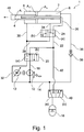
- the linear drive 1 has a hydraulic cylinder 2 which, as will be explained in more detail below, is designed with three pressure chambers 4, 6, 8.
- the pressure medium is supplied via a hydraulic machine 10, preferably a constant pump, which is driven by a variable-speed motor 12.
- a suction connection of the pump is connected via a low pressure line 14 to a low pressure source 16, for example a hydraulic accumulator or a tank.
- a pressure connection of the hydraulic machine 10 is connected to a pressure line 18, which leads to the single-port connection of a directional valve 20.
- this is designed as a 4/2-way switching valve, wherein in a basic position (a) shown, the pressure line 18 is connected to a supply line 22, which in turn leads to the input port of a control valve 24, which is also a 4/2-way Switch valve is executed.
- the third pressure chamber 8 is connected to a further output connection of the control valve 24 via a third working line 34, which is only shown for the purposes of the drawing.
- This working line 34 can also be combined with the suction line 36, which will be explained below.
- this third working line 34 to the supply line 22, the regeneration line 28 and the working line 26 is shut off.
- the control valve 24 into position (b) the third working line 34 is connected to the working line 26 and the supply line 22.
- the third pressure chamber 8 is additionally connected to the low pressure line 14 via a suction line 36 with a check valve 38 which is open towards the third pressure chamber 8.
- a storage valve 40 which is designed as a 3/2-way switching valve in the exemplary embodiment.
- the low-pressure source 16 In its basic position (a) shown, the low-pressure source 16 is connected to the low-pressure line 14.
- the low-pressure source 16 By switching over the storage valve 40, the low-pressure source 16 is connected to a line 42 leading into the supply line 22 and the connection to the low-pressure line 14 is blocked.
- the line 42 is shut off in the position (a) of the storage valve 40 to the low pressure source 16.
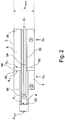
- the hydraulic cylinder 2 is designed with a piston 44 which has a hollow piston rod 46 into which a rod 50 supported on the cylinder base 48 dips so that an inner end face 52 of the hollow piston rod 46 and the end face of the rod 50 delimit the first pressure chamber 4. Its pressure supply takes place via a channel 54 which extends through the rod 50 and is connected to the working line 26.
- a piston rod-side ring end face 56 of the piston 54 delimits in the axial direction the second pressure chamber 6, through which the hollow piston rod 46 passes, and another rod-side ring end surface 58 delimits the third pressure chamber 8, through which the rod 50 passes.
- the active surfaces of these pressure chambers are shown in Figure 2 marked with the designations A1, A2, A3.
- the pressure chamber 6 is as based on Figure 1 explained, connected to the further working line 30 and the pressure chamber 8 to the third working line 34 and 36.
- the pressure medium volume flows Q 1 , Q 2 , Q 3 to the pressure chambers 4, 6 and 8 are also shown, which can be set by suitable control of the hydraulic machine 10.
- the hydraulic machine In order to set a rapid extension movement of the hollow piston rod 46 at high speed or high acceleration, the hydraulic machine is to promote a volume flow Q P with a predetermined pressure, which is to act on a comparatively small area of the hydraulic cylinder 2 which is effective in the extension direction, so that it has a comparatively low volume flow - and the associated low drive power - a high extension speed of the hydraulic cylinder 2 can be effected.
- the directional valve 20 and the control valve 24 are brought into their positions marked with (a).
- the storage valve 40 is also switched to position (a), so that pressure medium is drawn in from the low pressure source 16 via the hydraulic machine 10 and is conveyed into the first pressure chamber 4 via the supply line 22, the working line 26 and the channel 54.
- the regeneration line 28 is connected to the working line 26, so that the two pressure chambers 4, 6 are also connected to one another.
- the third pressure chamber 8 is in rapid traverse via the suction line 36 and the check valve 48 opening towards the pressure chamber 8 with the Low pressure line 14 and thus connected to the low pressure source 16.
- a pressure medium volume flow is supplied to the pressure chamber 4 with the active area A 1 via the hydraulic machine 10, so that the hollow piston rod 46 extends in the direction of the arrow.
- the pressure medium is pushed out of the shrinking second pressure chamber 6 and added via the regeneration line 28 to the pressure medium volume flow Q P conveyed by the hydraulic machine 10.
- the third pressure chamber 8 increases, so that pressure medium is sucked in from the low-pressure source 16 via the check valve 48.
- the hollow piston rod 46 thus extends at a comparatively high speed with a relatively low pressure medium volume flow.
- the volume flows Q 1 , Q 2 are calculated from the product of the extension speed x with the respective effective area A 1 , A 2 .
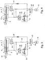
- the hollow piston rod 46 is extended at a comparatively low speed and great force.
- the hydraulic machine 10 must be in accordance with Figure 3 Promote a pressure medium volume Q p force to the largest possible effective area in order to generate the desired large force.
- the control valve 24 and the control valve 20 switched into their switching positions (b).
- the storage valve 40 remains in position (a). Accordingly, the first pressure chamber 4 with a comparatively large effective area A 1 is supplied with pressure medium.
- the effective area A 3 of the third pressure chamber 8 acting in the same direction is also acted upon by the pressure of the hydraulic machine 10.
- the effective area A 2 of the second pressure chamber 6 acting in the opposite direction is connected via the further working line 30, the directional control valve 20 and the return line 32 to the low-pressure line 14 and thus to the suction side of the hydraulic machine 10 - the hollow piston rod 46 is subjected to great force at low speed x extended.
- the active surfaces A 1 , A 2 , A 3 are designed and interconnectable in such a way that the motor 12 operates at approximately the same speed or with approximately the same torque, both in the power stroke and in the rapid traverse (back and forth), the desired traversing speed x or force (px A) is then achieved by suitable interconnection.
- FIG. 5 shows the linear drive during the power stroke - exactly as in the exemplary embodiment described above, the directional valve 20 and the control valve 24 are adjusted to their switching positions (a), so that the active surfaces A 1 , A 3 are acted upon by the pressure at the outlet of the hydraulic machine 10.
- the second pressure chamber 6 is connected to the low pressure source 16 via the further working line 30, the directional control valve 20, the return line 32 and the low pressure line 14, so that the pressure medium can be pushed out of the third pressure chamber 6.
- the directional valve 20 and the control valve 24 are in accordance with Figure 6 adjusted to their positions (b).
- the first pressure chamber 4 and the second pressure chamber 6 are connected to one another, so that the pressure medium ejected from the latter via the Regeneration line 28 is summed to the pressure medium volume flow flowing to the first pressure chamber 4.
- pressure medium is sucked in via the suction line 36 and the check valve 38 from the low pressure source into the increasing third pressure chamber 8.
- the directional valve 20 and the control valve 24 are adjusted into their positions (a) (not shown) and the direction of rotation of the hydraulic machine 10 is reversed (see Figure 4 ), so that the two pressure chambers 4, 8 are connected to the suction side of the hydraulic machine 10 and the hydraulic machine 10 conveys pressure medium into the second pressure chamber 6. The pressure medium that was previously removed is then fed to the low-pressure accumulator 16.
- a hydraulic linear drive with a hydraulic cylinder designed with three pressure chambers, the effective surfaces of which are coordinated with one another in such a way that in a rapid traverse and in a power stroke, a drive of a hydraulic machine supplying the hydraulic cylinder with pressure medium operates in approximately the same speed / torque range.
Landscapes
- Engineering & Computer Science (AREA)
- Physics & Mathematics (AREA)
- Fluid Mechanics (AREA)
- Mechanical Engineering (AREA)
- General Engineering & Computer Science (AREA)
- Fluid-Pressure Circuits (AREA)
- Actuator (AREA)
- Supply Devices, Intensifiers, Converters, And Telemotors (AREA)
Claims (10)
- Entraînement linéaire hydraulique comprenant un cylindre hydraulique (2) qui comporte trois chambres de pression (4, 6, 8) qui sont délimitées chacune par une surface active (A1, A2, A3) et qui peuvent être soumises à une haute pression ou une basse pression par une machine hydraulique (10) et un ensemble de soupapes de l'entraînement linéaire pour déplacer le cylindre hydraulique (2) suivant une marche rapide ou une course forcée dans un sens ou suivant une marche rapide ou une course forcée dans l'autre sens, l'ensemble de soupapes comportant un tiroir de distribution (20) qui, dans une première position (b), relie un raccord sous pression de la machine hydraulique (10) à une première (4) des chambres de pression (4, 6, 8) par le biais d'une conduite de travail (26) et une deuxième (6) des chambres de pression (4, 6, 8) à une source de basse pression (16) par le biais d'une autre conduite de travail (30) et qui, dans une deuxième position (a), bloque la liaison de la deuxième chambre de pression (6) à la source de basse pression (16), une soupape de commande (24) étant disposée en aval du tiroir de distribution (20) dans le sens de mise sous pression, laquelle soupape de commande relie, dans une position (a), la première chambre de pression (4) à la deuxième chambre de pression (6) active dans le sens opposé et, dans l'autre position (b), la première chambre de pression à la troisième chambre de pression (8) et une liaison de fluide sous pression de la troisième chambre de pression (8) à la machine hydraulique (10) étant bloquée lorsque la soupape de commande (24) est dans la position (a), caractérisé en ce que la machine hydraulique (10) comporte un entraînement à vitesse de rotation variable (12) et en ce que les rapports de surface des surfaces actives (A1, A2, A3) sont accordés de telle sorte que, en marche rapide et en course forcée, l'entraînement (12) fonctionne dans la même gamme de vitesses de rotation et en ce que la troisième chambre de pression (8) est reliée à la source de basse pression (16) par le biais d'une conduite d'aspiration (36) et d'une soupape anti-retour (38) s'ouvrant en direction de la troisième chambre de pression (8).
- Entraînement linéaire hydraulique comprenant un cylindre hydraulique (2) qui comporte trois chambres de pression (4, 6, 8) qui sont délimitées chacune par une surface active (A1, A2, A3) et qui sont soumises à une haute pression ou une basse pression par le biais d'une machine hydraulique (10) et d'un ensemble de soupapes de l'entraînement linéaire pour déplacer le cylindre hydraulique (2) suivant une marche rapide ou une course forcée dans un sens ou suivant une marche rapide ou une course forcée dans l'autre sens, l'ensemble de soupapes comportant un tiroir de distribution (20) qui, dans une première position (b), relie un raccord sous pression de la machine hydraulique (10) à une première (4) des chambres de pression (4, 6, 8) par le biais d'une conduite de travail (26) et une deuxième (6) des chambres de pression (4, 6, 8) à une source de basse pression (16) par le biais d'une autre conduite de travail (30) et qui, dans une deuxième position (a), bloque la liaison de la deuxième chambre de pression (6) à la source de basse pression (16), une soupape de commande (24) étant disposée en aval du tiroir de distribution (20) dans le sens de mise sous pression, laquelle soupape de commande relie, dans une position (a), la première chambre de pression (4) à la deuxième chambre de pression (6) active dans le sens opposé et, dans l'autre position (b), la première chambre de pression à la troisième chambre de pression (8), et une liaison de fluide sous pression de la troisième chambre de pression (8) à la machine hydraulique (10) étant bloquée lorsque la soupape de commande (24) est dans la position (a), caractérisé en ce que la machine hydraulique (10) comporte un entraînement à vitesse de rotation variable (12) et en ce que les rapports de surface des surfaces actives (A1, A2, A3) sont accordés de telle sorte que l'entraînement (12) fonctionne dans la même gamme de vitesses de rotation en marche rapide vitesse et en course forcée, et en ce que la troisième chambre de pression (8) est reliée à un côté basse pression de la machine hydraulique (10) par le biais d'une conduite d'aspiration (36) et d'une soupape anti-retour (38) s'ouvrant en direction de la troisième chambre de pression (8) et en ce qu'une soupape d'accumulateur (40) de l'entraînement linéaire est prévue qui relie, dans une position (a), la source de basse pression (16) au côté basse pression de la machine hydraulique (10) et, dans l'autre position (b), la source de basse pression (16) à une conduite d'alimentation (22) située entre le tiroir de distribution (20) et la soupape de commande (24).
- Entraînement linéaire selon la revendication 1 ou 2, la machine hydraulique (10) étant une machine à volume de transport/débit constant.
- Entraînement linéaire selon la revendication 1 ou la revendication 3 en combinaison avec la revendication 1, comprenant une soupape d'accumulateur (40) qui, dans une position (a), relie la source de basse pression (16) à un côté basse pression de la machine hydraulique (10) et, dans l'autre position (b), la source de basse pression (16) à une conduite d'alimentation (22) située entre le tiroir de distribution (20) et la soupape de commande (24).
- Entraînement linéaire selon l'une des revendications précédentes, la première chambre de pression (4) présentant une surface active (A1) supérieure à celle de la deuxième chambre de pression (6) agissant dans le sens opposé.
- Entraînement linéaire selon la revendication 5, la surface active (A2) de la deuxième chambre de pression (6) étant légèrement inférieure à la surface active (A3) de la troisième chambre de pression (8).
- Entraînement linéaire selon l'une des revendications précédentes, l'entraînement à vitesse de rotation variable étant réalisé sous la forme d'un moteur (12) ou la machine hydraulique (10) étant conçue avec un dispositif d'inversion du sens de rotation.
- Entraînement linéaire selon l'une des revendications précédentes, celui-ci pouvant être utilisé comme entraînement d'une machine de formage ou d'une machine d'injection/soufflage.
- Entraînement linéaire selon l'une des revendications précédentes, le cylindre hydraulique (2) comportant un piston (44) pourvu d'une tige de piston creuse (46) dans laquelle pénètre une tige (50) du cylindre hydraulique (2) de telle sorte que la première chambre de pression (4), qui est alimentée en fluide sous pression à travers la tige (50), soit limitée axialement par une face frontale intérieure (52) de la tige de piston creuse (46) et la face frontale de la tige (50).
- Entraînement linéaire selon la revendication 9, une face frontale annulaire côté tige de piston (A2) du piston (44) délimitant la deuxième chambre de pression (6) et une face frontale annulaire (A3) du piston (44), laquelle est opposée à la précédente, délimitant la troisième chambre de pression (8) dans la direction axiale.
Applications Claiming Priority (1)
| Application Number | Priority Date | Filing Date | Title |
|---|---|---|---|
| DE102010034610A DE102010034610A1 (de) | 2010-08-18 | 2010-08-18 | Hydraulischer Linearantrieb |
Publications (3)
| Publication Number | Publication Date |
|---|---|
| EP2420681A2 EP2420681A2 (fr) | 2012-02-22 |
| EP2420681A3 EP2420681A3 (fr) | 2014-09-24 |
| EP2420681B1 true EP2420681B1 (fr) | 2020-01-08 |
Family
ID=44650824
Family Applications (1)
| Application Number | Title | Priority Date | Filing Date |
|---|---|---|---|
| EP11006709.7A Active EP2420681B1 (fr) | 2010-08-18 | 2011-08-17 | Entraînement linéaire hydraulique |
Country Status (2)
| Country | Link |
|---|---|
| EP (1) | EP2420681B1 (fr) |
| DE (1) | DE102010034610A1 (fr) |
Families Citing this family (9)
| Publication number | Priority date | Publication date | Assignee | Title |
|---|---|---|---|---|
| JP6479306B2 (ja) * | 2013-08-05 | 2019-03-06 | 住友重機械工業株式会社 | ショベル |
| WO2015019839A1 (fr) * | 2013-08-05 | 2015-02-12 | 住友重機械工業株式会社 | Pelle |
| JP6385654B2 (ja) * | 2013-08-05 | 2018-09-05 | 住友重機械工業株式会社 | ショベル |
| WO2016008151A1 (fr) * | 2014-07-18 | 2016-01-21 | Norgren, Inc. | Cylindre de moulage par soufflage avec étirage et procédé associé |
| DE102015211796A1 (de) * | 2015-06-25 | 2016-12-29 | Robert Bosch Gmbh | Hydraulisches System zur Druckmittelversorgung eines Hydrozylinders mit drei getrennten druckmittelbeaufschlagbaren Wirkflächen und Verfahren zum Betreiben des hydraulischen Systems |
| DE102016214767A1 (de) * | 2016-02-16 | 2017-08-17 | Sms Group Gmbh | Gleichgangzylinder für Strangpressanlagen |
| CN107243774B (zh) * | 2017-05-19 | 2019-11-08 | 深圳市睿格晟设备有限公司 | 一种改良吸屑机 |
| DE102018203367A1 (de) | 2018-03-07 | 2019-09-12 | Robert Bosch Gmbh | Hydrostatischer Linearantrieb |
| DE102019105449A1 (de) * | 2019-03-04 | 2020-09-10 | Wacker Neuson Linz Gmbh | Linearantrieb mit geschlossenem Hydraulikkreislauf |
Family Cites Families (4)
| Publication number | Priority date | Publication date | Assignee | Title |
|---|---|---|---|---|
| NL8105929A (nl) * | 1981-12-31 | 1983-07-18 | Hydraudyne Bv | Zuiger/cilinder eenheid. |
| US5522212A (en) | 1994-12-21 | 1996-06-04 | Kubik; Philip A. | Rod equal displacement cylinder in a rapid transfer and feed system |
| DE102004027849A1 (de) * | 2004-06-08 | 2006-01-05 | Bosch Rexroth Aktiengesellschaft | Antriebseinheit |
| DE102008039011B4 (de) | 2008-08-21 | 2020-01-16 | MAE Maschinen- u. Apparatebau Götzen GmbH | Druckspeicherlose hydraulische Antriebsanordnung sowie Verfahren zum druckspeicherlosen hydraulischen Antreiben eines Verbrauchers |
-
2010
- 2010-08-18 DE DE102010034610A patent/DE102010034610A1/de not_active Ceased
-
2011
- 2011-08-17 EP EP11006709.7A patent/EP2420681B1/fr active Active
Non-Patent Citations (1)
| Title |
|---|
| None * |
Also Published As
| Publication number | Publication date |
|---|---|
| EP2420681A2 (fr) | 2012-02-22 |
| EP2420681A3 (fr) | 2014-09-24 |
| DE102010034610A1 (de) | 2012-02-23 |
Similar Documents
| Publication | Publication Date | Title |
|---|---|---|
| EP2420681B1 (fr) | Entraînement linéaire hydraulique | |
| EP2480405B1 (fr) | Entrainement hydraulique precontraint dote d'une pompe a vitesse variable | |
| DE102011000473B4 (de) | Pressmaschine und Verfahren zum Pressen von Werkstücken | |
| EP2722165B1 (fr) | Circuit hydraulique pour un axe hydraulique et axe hydraulique | |
| EP2732959A2 (fr) | Agencement d'entraînement hydraulique sans accumulateur de pression pour et avec un consommateur, notamment pour presse hydraulique, et procédé d'entraînement hydraulique sans accumulateur de pression d'un consommateur | |
| EP3880975B1 (fr) | Système d'actionneur électrohydrostatique | |
| EP2267317A2 (fr) | Système hydraulique | |
| DE102009040126A1 (de) | Elektromotorischer Hydraulikantrieb und Verfahren zum Bereitstellen eines definierten Hydraulikdrucks und/oder -volumens | |
| EP1706648B1 (fr) | Dispositif d'entrainement | |
| DE102013224657A1 (de) | Hydraulische Anordnung | |
| EP1656224B1 (fr) | Systeme pour commander le processus d'etirage dans une presse de transfert | |
| EP1181458B1 (fr) | Commande hydraulique comportant plusieurs consommateurs hydrauliques comprenant egalement un verin differentiel | |
| WO2023041476A1 (fr) | Système d'entraînement hydraulique doté d'une unité pompe 4q | |
| DE102012009182A1 (de) | Hydraulische Strangpresse sowie Verfahren zum Betrieb einer hydraulischen Strangpresse | |
| DE102013007148B4 (de) | Hydraulischer Pressantrieb mit Energierückspeisung | |
| DE10239591B4 (de) | Einzelmotoreinspritz- und Schraubenantriebshybridaktuator | |
| DE102017000523B4 (de) | Hydraulikvorrichtung für eine Formgebungsmaschine | |
| WO2002076703A2 (fr) | Dispositif de serrage electromecanique | |
| EP2229537B1 (fr) | Dispositif d'entraînement hydraulique à deux chambres de pression, et procédé permettant de faire fonctionner un dispositif d'entraînement hydraulique à deux chambres de pression | |
| DE102018203367A1 (de) | Hydrostatischer Linearantrieb | |
| EP0751842B1 (fr) | Presse double | |
| DE102010024246A1 (de) | Verfahren und Vorrichtung zum Betrieb einer angetriebenen Achse bei einer Werkzeugmaschine | |
| DE10104109A1 (de) | Regelverfahren für die hydraulische Unterstützung eines elektrischen Antriebs | |
| EP1754595B1 (fr) | Module d'entraînement pour presse et procédé pour fournir une gamme de presses | |
| DE102009036350B4 (de) | Antriebsvorrichtung |
Legal Events
| Date | Code | Title | Description |
|---|---|---|---|
| AK | Designated contracting states |
Kind code of ref document: A2 Designated state(s): AL AT BE BG CH CY CZ DE DK EE ES FI FR GB GR HR HU IE IS IT LI LT LU LV MC MK MT NL NO PL PT RO RS SE SI SK SM TR |
|
| AX | Request for extension of the european patent |
Extension state: BA ME |
|
| PUAI | Public reference made under article 153(3) epc to a published international application that has entered the european phase |
Free format text: ORIGINAL CODE: 0009012 |
|
| RIN1 | Information on inventor provided before grant (corrected) |
Inventor name: BECKMANN, BASTIAN |
|
| PUAL | Search report despatched |
Free format text: ORIGINAL CODE: 0009013 |
|
| AK | Designated contracting states |
Kind code of ref document: A3 Designated state(s): AL AT BE BG CH CY CZ DE DK EE ES FI FR GB GR HR HU IE IS IT LI LT LU LV MC MK MT NL NO PL PT RO RS SE SI SK SM TR |
|
| AX | Request for extension of the european patent |
Extension state: BA ME |
|
| RIC1 | Information provided on ipc code assigned before grant |
Ipc: F15B 11/024 20060101AFI20140815BHEP Ipc: F15B 11/036 20060101ALI20140815BHEP |
|
| 17P | Request for examination filed |
Effective date: 20150324 |
|
| RBV | Designated contracting states (corrected) |
Designated state(s): AL AT BE BG CH CY CZ DE DK EE ES FI FR GB GR HR HU IE IS IT LI LT LU LV MC MK MT NL NO PL PT RO RS SE SI SK SM TR |
|
| STAA | Information on the status of an ep patent application or granted ep patent |
Free format text: STATUS: EXAMINATION IS IN PROGRESS |
|
| 17Q | First examination report despatched |
Effective date: 20180703 |
|
| GRAP | Despatch of communication of intention to grant a patent |
Free format text: ORIGINAL CODE: EPIDOSNIGR1 |
|
| STAA | Information on the status of an ep patent application or granted ep patent |
Free format text: STATUS: GRANT OF PATENT IS INTENDED |
|
| INTG | Intention to grant announced |
Effective date: 20191018 |
|
| GRAS | Grant fee paid |
Free format text: ORIGINAL CODE: EPIDOSNIGR3 |
|
| GRAA | (expected) grant |
Free format text: ORIGINAL CODE: 0009210 |
|
| STAA | Information on the status of an ep patent application or granted ep patent |
Free format text: STATUS: THE PATENT HAS BEEN GRANTED |
|
| AK | Designated contracting states |
Kind code of ref document: B1 Designated state(s): AL AT BE BG CH CY CZ DE DK EE ES FI FR GB GR HR HU IE IS IT LI LT LU LV MC MK MT NL NO PL PT RO RS SE SI SK SM TR |
|
| REG | Reference to a national code |
Ref country code: GB Ref legal event code: FG4D Free format text: NOT ENGLISH |
|
| REG | Reference to a national code |
Ref country code: CH Ref legal event code: EP |
|
| REG | Reference to a national code |
Ref country code: DE Ref legal event code: R096 Ref document number: 502011016370 Country of ref document: DE |
|
| REG | Reference to a national code |
Ref country code: IE Ref legal event code: FG4D Free format text: LANGUAGE OF EP DOCUMENT: GERMAN |
|
| REG | Reference to a national code |
Ref country code: AT Ref legal event code: REF Ref document number: 1223079 Country of ref document: AT Kind code of ref document: T Effective date: 20200215 |
|
| RAP2 | Party data changed (patent owner data changed or rights of a patent transferred) |
Owner name: ROBERT BOSCH GMBH |
|
| REG | Reference to a national code |
Ref country code: NL Ref legal event code: MP Effective date: 20200108 |
|
| REG | Reference to a national code |
Ref country code: LT Ref legal event code: MG4D |
|
| PG25 | Lapsed in a contracting state [announced via postgrant information from national office to epo] |
Ref country code: LT Free format text: LAPSE BECAUSE OF FAILURE TO SUBMIT A TRANSLATION OF THE DESCRIPTION OR TO PAY THE FEE WITHIN THE PRESCRIBED TIME-LIMIT Effective date: 20200108 Ref country code: NL Free format text: LAPSE BECAUSE OF FAILURE TO SUBMIT A TRANSLATION OF THE DESCRIPTION OR TO PAY THE FEE WITHIN THE PRESCRIBED TIME-LIMIT Effective date: 20200108 Ref country code: NO Free format text: LAPSE BECAUSE OF FAILURE TO SUBMIT A TRANSLATION OF THE DESCRIPTION OR TO PAY THE FEE WITHIN THE PRESCRIBED TIME-LIMIT Effective date: 20200408 Ref country code: FI Free format text: LAPSE BECAUSE OF FAILURE TO SUBMIT A TRANSLATION OF THE DESCRIPTION OR TO PAY THE FEE WITHIN THE PRESCRIBED TIME-LIMIT Effective date: 20200108 Ref country code: PT Free format text: LAPSE BECAUSE OF FAILURE TO SUBMIT A TRANSLATION OF THE DESCRIPTION OR TO PAY THE FEE WITHIN THE PRESCRIBED TIME-LIMIT Effective date: 20200531 Ref country code: RS Free format text: LAPSE BECAUSE OF FAILURE TO SUBMIT A TRANSLATION OF THE DESCRIPTION OR TO PAY THE FEE WITHIN THE PRESCRIBED TIME-LIMIT Effective date: 20200108 |
|
| PG25 | Lapsed in a contracting state [announced via postgrant information from national office to epo] |
Ref country code: HR Free format text: LAPSE BECAUSE OF FAILURE TO SUBMIT A TRANSLATION OF THE DESCRIPTION OR TO PAY THE FEE WITHIN THE PRESCRIBED TIME-LIMIT Effective date: 20200108 Ref country code: LV Free format text: LAPSE BECAUSE OF FAILURE TO SUBMIT A TRANSLATION OF THE DESCRIPTION OR TO PAY THE FEE WITHIN THE PRESCRIBED TIME-LIMIT Effective date: 20200108 Ref country code: SE Free format text: LAPSE BECAUSE OF FAILURE TO SUBMIT A TRANSLATION OF THE DESCRIPTION OR TO PAY THE FEE WITHIN THE PRESCRIBED TIME-LIMIT Effective date: 20200108 Ref country code: BG Free format text: LAPSE BECAUSE OF FAILURE TO SUBMIT A TRANSLATION OF THE DESCRIPTION OR TO PAY THE FEE WITHIN THE PRESCRIBED TIME-LIMIT Effective date: 20200408 Ref country code: IS Free format text: LAPSE BECAUSE OF FAILURE TO SUBMIT A TRANSLATION OF THE DESCRIPTION OR TO PAY THE FEE WITHIN THE PRESCRIBED TIME-LIMIT Effective date: 20200508 Ref country code: GR Free format text: LAPSE BECAUSE OF FAILURE TO SUBMIT A TRANSLATION OF THE DESCRIPTION OR TO PAY THE FEE WITHIN THE PRESCRIBED TIME-LIMIT Effective date: 20200409 |
|
| REG | Reference to a national code |
Ref country code: DE Ref legal event code: R097 Ref document number: 502011016370 Country of ref document: DE |
|
| PG25 | Lapsed in a contracting state [announced via postgrant information from national office to epo] |
Ref country code: CZ Free format text: LAPSE BECAUSE OF FAILURE TO SUBMIT A TRANSLATION OF THE DESCRIPTION OR TO PAY THE FEE WITHIN THE PRESCRIBED TIME-LIMIT Effective date: 20200108 Ref country code: SK Free format text: LAPSE BECAUSE OF FAILURE TO SUBMIT A TRANSLATION OF THE DESCRIPTION OR TO PAY THE FEE WITHIN THE PRESCRIBED TIME-LIMIT Effective date: 20200108 Ref country code: DK Free format text: LAPSE BECAUSE OF FAILURE TO SUBMIT A TRANSLATION OF THE DESCRIPTION OR TO PAY THE FEE WITHIN THE PRESCRIBED TIME-LIMIT Effective date: 20200108 Ref country code: EE Free format text: LAPSE BECAUSE OF FAILURE TO SUBMIT A TRANSLATION OF THE DESCRIPTION OR TO PAY THE FEE WITHIN THE PRESCRIBED TIME-LIMIT Effective date: 20200108 Ref country code: SM Free format text: LAPSE BECAUSE OF FAILURE TO SUBMIT A TRANSLATION OF THE DESCRIPTION OR TO PAY THE FEE WITHIN THE PRESCRIBED TIME-LIMIT Effective date: 20200108 Ref country code: ES Free format text: LAPSE BECAUSE OF FAILURE TO SUBMIT A TRANSLATION OF THE DESCRIPTION OR TO PAY THE FEE WITHIN THE PRESCRIBED TIME-LIMIT Effective date: 20200108 Ref country code: RO Free format text: LAPSE BECAUSE OF FAILURE TO SUBMIT A TRANSLATION OF THE DESCRIPTION OR TO PAY THE FEE WITHIN THE PRESCRIBED TIME-LIMIT Effective date: 20200108 |
|
| PLBE | No opposition filed within time limit |
Free format text: ORIGINAL CODE: 0009261 |
|
| STAA | Information on the status of an ep patent application or granted ep patent |
Free format text: STATUS: NO OPPOSITION FILED WITHIN TIME LIMIT |
|
| 26N | No opposition filed |
Effective date: 20201009 |
|
| PG25 | Lapsed in a contracting state [announced via postgrant information from national office to epo] |
Ref country code: IT Free format text: LAPSE BECAUSE OF FAILURE TO SUBMIT A TRANSLATION OF THE DESCRIPTION OR TO PAY THE FEE WITHIN THE PRESCRIBED TIME-LIMIT Effective date: 20200108 |
|
| PG25 | Lapsed in a contracting state [announced via postgrant information from national office to epo] |
Ref country code: PL Free format text: LAPSE BECAUSE OF FAILURE TO SUBMIT A TRANSLATION OF THE DESCRIPTION OR TO PAY THE FEE WITHIN THE PRESCRIBED TIME-LIMIT Effective date: 20200108 Ref country code: SI Free format text: LAPSE BECAUSE OF FAILURE TO SUBMIT A TRANSLATION OF THE DESCRIPTION OR TO PAY THE FEE WITHIN THE PRESCRIBED TIME-LIMIT Effective date: 20200108 |
|
| PG25 | Lapsed in a contracting state [announced via postgrant information from national office to epo] |
Ref country code: MC Free format text: LAPSE BECAUSE OF FAILURE TO SUBMIT A TRANSLATION OF THE DESCRIPTION OR TO PAY THE FEE WITHIN THE PRESCRIBED TIME-LIMIT Effective date: 20200108 |
|
| REG | Reference to a national code |
Ref country code: CH Ref legal event code: PL |
|
| GBPC | Gb: european patent ceased through non-payment of renewal fee |
Effective date: 20200817 |
|
| PG25 | Lapsed in a contracting state [announced via postgrant information from national office to epo] |
Ref country code: CH Free format text: LAPSE BECAUSE OF NON-PAYMENT OF DUE FEES Effective date: 20200831 Ref country code: LI Free format text: LAPSE BECAUSE OF NON-PAYMENT OF DUE FEES Effective date: 20200831 Ref country code: LU Free format text: LAPSE BECAUSE OF NON-PAYMENT OF DUE FEES Effective date: 20200817 |
|
| REG | Reference to a national code |
Ref country code: BE Ref legal event code: MM Effective date: 20200831 |
|
| PG25 | Lapsed in a contracting state [announced via postgrant information from national office to epo] |
Ref country code: FR Free format text: LAPSE BECAUSE OF NON-PAYMENT OF DUE FEES Effective date: 20200831 |
|
| PG25 | Lapsed in a contracting state [announced via postgrant information from national office to epo] |
Ref country code: BE Free format text: LAPSE BECAUSE OF NON-PAYMENT OF DUE FEES Effective date: 20200831 Ref country code: IE Free format text: LAPSE BECAUSE OF NON-PAYMENT OF DUE FEES Effective date: 20200817 Ref country code: GB Free format text: LAPSE BECAUSE OF NON-PAYMENT OF DUE FEES Effective date: 20200817 |
|
| REG | Reference to a national code |
Ref country code: AT Ref legal event code: MM01 Ref document number: 1223079 Country of ref document: AT Kind code of ref document: T Effective date: 20200817 |
|
| PG25 | Lapsed in a contracting state [announced via postgrant information from national office to epo] |
Ref country code: AT Free format text: LAPSE BECAUSE OF NON-PAYMENT OF DUE FEES Effective date: 20200817 |
|
| PG25 | Lapsed in a contracting state [announced via postgrant information from national office to epo] |
Ref country code: TR Free format text: LAPSE BECAUSE OF FAILURE TO SUBMIT A TRANSLATION OF THE DESCRIPTION OR TO PAY THE FEE WITHIN THE PRESCRIBED TIME-LIMIT Effective date: 20200108 Ref country code: MT Free format text: LAPSE BECAUSE OF FAILURE TO SUBMIT A TRANSLATION OF THE DESCRIPTION OR TO PAY THE FEE WITHIN THE PRESCRIBED TIME-LIMIT Effective date: 20200108 Ref country code: CY Free format text: LAPSE BECAUSE OF FAILURE TO SUBMIT A TRANSLATION OF THE DESCRIPTION OR TO PAY THE FEE WITHIN THE PRESCRIBED TIME-LIMIT Effective date: 20200108 |
|
| PG25 | Lapsed in a contracting state [announced via postgrant information from national office to epo] |
Ref country code: MK Free format text: LAPSE BECAUSE OF FAILURE TO SUBMIT A TRANSLATION OF THE DESCRIPTION OR TO PAY THE FEE WITHIN THE PRESCRIBED TIME-LIMIT Effective date: 20200108 Ref country code: AL Free format text: LAPSE BECAUSE OF FAILURE TO SUBMIT A TRANSLATION OF THE DESCRIPTION OR TO PAY THE FEE WITHIN THE PRESCRIBED TIME-LIMIT Effective date: 20200108 |
|
| PGFP | Annual fee paid to national office [announced via postgrant information from national office to epo] |
Ref country code: DE Payment date: 20251021 Year of fee payment: 15 |