EP2420820A2 - Procédé de vérification de composants fragmentés - Google Patents
Procédé de vérification de composants fragmentés Download PDFInfo
- Publication number
- EP2420820A2 EP2420820A2 EP10004098A EP10004098A EP2420820A2 EP 2420820 A2 EP2420820 A2 EP 2420820A2 EP 10004098 A EP10004098 A EP 10004098A EP 10004098 A EP10004098 A EP 10004098A EP 2420820 A2 EP2420820 A2 EP 2420820A2
- Authority
- EP
- European Patent Office
- Prior art keywords
- connecting rod
- break point
- offset
- rod bore
- edge
- Prior art date
- Legal status (The legal status is an assumption and is not a legal conclusion. Google has not performed a legal analysis and makes no representation as to the accuracy of the status listed.)
- Granted
Links
Images
Classifications
-
- G—PHYSICS
- G01—MEASURING; TESTING
- G01M—TESTING STATIC OR DYNAMIC BALANCE OF MACHINES OR STRUCTURES; TESTING OF STRUCTURES OR APPARATUS, NOT OTHERWISE PROVIDED FOR
- G01M11/00—Testing of optical apparatus; Testing structures by optical methods not otherwise provided for
- G01M11/08—Testing mechanical properties
- G01M11/081—Testing mechanical properties by using a contact-less detection method, i.e. with a camera
-
- G—PHYSICS
- G01—MEASURING; TESTING
- G01M—TESTING STATIC OR DYNAMIC BALANCE OF MACHINES OR STRUCTURES; TESTING OF STRUCTURES OR APPARATUS, NOT OTHERWISE PROVIDED FOR
- G01M13/00—Testing of machine parts
- G01M13/02—Gearings; Transmission mechanisms
-
- G—PHYSICS
- G01—MEASURING; TESTING
- G01N—INVESTIGATING OR ANALYSING MATERIALS BY DETERMINING THEIR CHEMICAL OR PHYSICAL PROPERTIES
- G01N21/00—Investigating or analysing materials by the use of optical means, i.e. using sub-millimetre waves, infrared, visible or ultraviolet light
- G01N21/84—Systems specially adapted for particular applications
- G01N21/88—Investigating the presence of flaws or contamination
- G01N21/8806—Specially adapted optical and illumination features
-
- F—MECHANICAL ENGINEERING; LIGHTING; HEATING; WEAPONS; BLASTING
- F16—ENGINEERING ELEMENTS AND UNITS; GENERAL MEASURES FOR PRODUCING AND MAINTAINING EFFECTIVE FUNCTIONING OF MACHINES OR INSTALLATIONS; THERMAL INSULATION IN GENERAL
- F16C—SHAFTS; FLEXIBLE SHAFTS; ELEMENTS OR CRANKSHAFT MECHANISMS; ROTARY BODIES OTHER THAN GEARING ELEMENTS; BEARINGS
- F16C9/00—Bearings for crankshafts or connecting-rods; Attachment of connecting-rods
- F16C9/04—Connecting-rod bearings; Attachments thereof
- F16C9/045—Connecting-rod bearings; Attachments thereof the bearing cap of the connecting rod being split by fracturing
-
- G—PHYSICS
- G01—MEASURING; TESTING
- G01N—INVESTIGATING OR ANALYSING MATERIALS BY DETERMINING THEIR CHEMICAL OR PHYSICAL PROPERTIES
- G01N21/00—Investigating or analysing materials by the use of optical means, i.e. using sub-millimetre waves, infrared, visible or ultraviolet light
- G01N21/84—Systems specially adapted for particular applications
- G01N21/88—Investigating the presence of flaws or contamination
- G01N21/8806—Specially adapted optical and illumination features
- G01N2021/8841—Illumination and detection on two sides of object
-
- G—PHYSICS
- G01—MEASURING; TESTING
- G01N—INVESTIGATING OR ANALYSING MATERIALS BY DETERMINING THEIR CHEMICAL OR PHYSICAL PROPERTIES
- G01N2203/00—Investigating strength properties of solid materials by application of mechanical stress
- G01N2203/0058—Kind of property studied
- G01N2203/006—Crack, flaws, fracture or rupture
- G01N2203/0067—Fracture or rupture
-
- G—PHYSICS
- G01—MEASURING; TESTING
- G01N—INVESTIGATING OR ANALYSING MATERIALS BY DETERMINING THEIR CHEMICAL OR PHYSICAL PROPERTIES
- G01N2203/00—Investigating strength properties of solid materials by application of mechanical stress
- G01N2203/02—Details not specific for a particular testing method
- G01N2203/06—Indicating or recording means; Sensing means
- G01N2203/0641—Indicating or recording means; Sensing means using optical, X-ray, ultraviolet, infrared or similar detectors
- G01N2203/0647—Image analysis
Definitions
- the invention relates to a method referred to in the preamble of claim 1 for the examination of fracture-separated components.
- Test devices used for this purpose may comprise, for example, tactile probe.
- a disadvantage of the known method is that it is less suitable in particular for an application in series production.
- the invention has for its object to provide a method referred to in the preamble of claim 1 for the examination of fracture-separated components, which does not have the disadvantage of the known method, that is for use in a mass production suitable is.
- the basic idea of the invention is to optically measure an offset between surfaces arranged on both sides of the fracture point in the direction of the surface normal.
- a further advantage of the invention is that a robust and, for example, with regard to the testing of connecting rods with different diameter of the connecting rod flexible test device can be used.
- the test device used may in particular have a large measuring range. Since, by means of the method according to the invention, connecting rods of different sizes, for example, can also be tested in immediate succession, the method according to the invention is particularly suitable for use in mass production.
- the method according to the invention is suitable for testing any suitable fracture-separated components, for example for testing fracture-separated molded housing parts.
- the method according to the invention is particularly well suited for testing fracture-separated connecting rods. Accordingly, an advantageous development of the invention that a fractured in the region of its connecting rod bore connecting rod is checked.
- An advantageous development of the aforementioned embodiment provides that at least one break point of the geometric offset of both sides of the fracture point arranged surfaces in the axial direction of the connecting rod bore is determined. In this embodiment, it is determined whether flat surfaces of the connecting rod in the axial direction of the connecting rod bore are offset from each other (plane surface offset).
- Another development of the invention provides that at least one break point of the geometric offset of both sides of the fracture point arranged surfaces in the radial direction of the connecting rod bore is determined.
- Particularly advantageous is a combination of this embodiment with the aforementioned, since then both the plane surface offset and the hole offset of a connecting rod can be determined.
- the geometric offset of the surfaces arranged on both sides of the break point is determined at a single break point.
- another advantageous development of the invention provides that a geometric offset of the surfaces arranged on both sides of the break point is determined at two break points diametrically opposite the connecting rod bore.
- An extraordinarily advantageous development of the invention provides that the edge profile of an edge formed by the surface arranged on both sides of the break point is optically detected. In this way, both the presence of an offset and the amount and direction of the offset are particularly determine quickly and with high accuracy. In addition, the method according to the invention works optically and thus without contact.
- a development of the aforementioned embodiment provides that the edge is photographed for the detection of the edge profile, wherein the edge is preferably digitally photographed and the edge profile is determined on the basis of the digital photo.
- the edge profile can be determined quickly and with great accuracy on the basis of the digital photo using algorithms of image processing.
- another expedient embodiment of the invention provides that at least one camera is associated with each break point.
- a particularly advantageous development of the aforementioned embodiment provides that at least one break point are assigned to two cameras, which photograph the break point from two different, preferably mutually substantially perpendicular directions. In this way, it is possible to determine an offset of the surfaces arranged on both sides of the fracture point, in particular simultaneously in two different directions.
- an advantageous development of the aforementioned embodiment provides that with a camera, the edge is photographed for determining an axial offset relative to the connecting rod bore in the radial direction of the connecting rod bore and with the other camera the edge for determining a relative to the Connecting rod bore radial offset is photographed in the axial direction of the connecting rod bore.
- the plane surface offset and the hole offset can be at the same time determine a crack connecting rod.
- each break point at least two cameras are assigned.
- a break is photographed by means of a digital camera
- a digital camera is used in which all pixels are exposed simultaneously.
- the measuring circuit on the image sensor of the digital camera closes.
- time-series operating method in which the parts of an edge formed at the fracture point at a time interval from each other, for example by means of a tactile probe working, scanned.
- any suitable light source can be used to illuminate the breakage point or fractures.
- An advantageous development of the invention provides insofar as the break point or at least one of the break points is diffusely illuminated by means of a light source.
- Such diffuse light sources have proven to be particularly suitable.
- a separate light source can be used to illuminate each breakpoint or edge to be detected.
- a common light source is used to illuminate all break points or edges, so that the structure of a test device used to carry out the method is relatively simple and therefore inexpensive.
- a test device according to the invention for testing fracture-separated components is specified in claim 14.
- the test device according to the invention has optical measuring means for measuring at least one break point with respect to surfaces arranged on both sides of the break point with respect to a geometric offset of the surfaces in the direction of the surface normal.
- the inventive device is relatively simple in construction and allows a fast, non-contact measurement of a breakage with high accuracy.
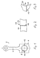
- a fracture-separated component in the form of a connecting rod 2 is shown, which is a so-called cracking connecting rod having a base body 4, from which a cover 6 is separated by means of a rupture of force. How out Fig. 1 it can be seen, the cover 6 is separated from the main body 4 at two to a connecting rod bore 8 diametrically opposite fractures 10, 12.
- Fig. 1 shows the connecting rod 2 after a reassembly of the base body 4 and the lid 6.
- a geometric offset between the fracture points both in the axial direction and in the radial direction of the connecting rod bore 8 occur. Since such an offset is undesirable and particularly disadvantageous in terms of the strength of the connecting rod 2, by means of a below with reference to FIGS. 4 and 5 closer explained embodiment of a method according to the invention for testing fracture-separated components using an embodiment of a test device according to the invention checked whether there is a geometric offset between the fracture surfaces.
- This is inventively at least one Fracture with respect to both sides of the fracture site arranged surfaces a geometric offset of the surfaces measured in the direction of the surface normal optically.
- Fig. 2 shows a side view of the connecting rod 2 of Fig. 1 in from the left in the region of the break point 10.
- Fig. 2 shows a side view of the connecting rod 2 of Fig. 1 in from the left in the region of the break point 10.
- an offset at the fracture point 10 between two sides of the fracture site arranged surfaces 14, 16 in the direction of the surface normal, with respect to Fig. 2 ie in the axial direction of the connecting rod bore 8, an offset.
- the surfaces 14, 16 form an edge 17, whose in Fig. 2 illustrated edge profile at the point at which the surfaces 14, 16 are offset in the axial direction of the connecting rod bore 8 to each other, having a point of discontinuity.
- Fig. 3 shows a view in Fig. 1 in the region of the break point 10 and the connecting rod bore 8.
- the surfaces 18, 20 form an edge 21, whose edge profile at the point at which the surfaces 18, 20 are offset from each other in the radial direction of the connecting rod bore 8, has a point of discontinuity.
- FIGS. 2 and 3 A fracture separation of the cover 6 from the base 4 resulting fracture of the fracture surfaces is in the FIGS. 2 and 3 for reasons of illustration greatly exaggerated.
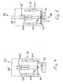
- test device 22 which serves to test the fracture-separated connecting rod 2.
- the tester has test means which determine whether there is a geometric offset between the fractured surfaces at at least one break point 10, 12.
- the test means comprise optical measuring means for measuring at least one break point 10, 12 with respect to a surface 14, 16 or 18, 20 disposed on either side of the break point 10, 12 with respect to a geometric offset of the surfaces 14, 16 and 18, 20 in the direction of Surface normals.
- the cameras 24, 26 are associated with the break point 10 and the cameras 24 ', 26' of the break point 12.
- the mode of operation of the cameras 24 ', 26' corresponds to that of the cameras 24, 26 and will therefore not be explained in more detail below.
- the cameras 24, 26, 24 ', 26' are arranged on a base body 28, which is height-adjustable in the direction of a double arrow 30 relative to a holder 32 for the connecting rod 2.
- the camera 26 photographs the connecting rod 2 in the region of the break point 10 in the axial direction of the connecting rod bore 8.
- the camera 24 photographs the breakage point 10 in the radial direction of the connecting rod bore 8.
- a deflection mirror 34 is arranged in the beam path of the camera 24, which deflects the beam path of the digital camera 24 by 90 °.
- the beam paths of the cameras 24, 26 at the imaging location to each other at an angle of about 90 °, so that the cameras 24, 26 photograph the break point 10 of two, in the embodiment substantially mutually perpendicular directions.
- the test apparatus 22 further includes a light source 36, which is formed in this embodiment by an LED light source and diffuses the imaging location diffused. How out Fig. 4 it can be seen, the light source 36 in the beam path of the cameras 24, 24 'and between the beam paths of the cameras 26, 26' is arranged. As a result, the image of the break point 10 in the axial direction of the connecting rod bore 8 by means of the camera 26 in bright field arrangement, while the image of the break point 10 in the axial direction of the connecting rod bore 8 by means of the camera 24 in transmitted light arrangement. With respect to the image of the break point 10 in the axial direction of the connecting rod bore 8 by means of the camera 26, it is advantageous if the axial edge of the connecting rod bore 8 is provided with a chamfer.
- the cameras 24, 26, 24 ', 26' are connected to a downstream evaluation device, in which by means of the cameras 24, 26, 24 ', 26' recorded images are stored. Based on the saved pictures the edge profile of an edge formed by the surfaces arranged on either side of the break point 10 is detected. This applies both to the edge course of the edge 17 on the surfaces 14, 16 (cf. Fig. 2 ) as well as for the edge course of the edge 21 on the surfaces 18, 20.
- the cameras 24, 26, 24 ', 26' are designed so that when taking up the break points 10, 12 all the pixels of the respective image sensor are exposed simultaneously. In this way it is prevented that vibrations of the connecting rod 2 or the holder 32 relative to the test device 22 lead to an impairment of the measurement results. This results in respect to time series operating method in terms of accuracy of the measurement results a significant advantage.
- test apparatus 22 in carrying out a method according to the invention is as follows:
- the main body 28 of the test apparatus 22 is lowered relative to the holder 32 with the connecting rod 2 such that the through the surfaces 14, 16 (see. Fig. 2 ) formed edge 17 in the beam path of the camera 24 and the edge 21 formed by the surfaces 18, 20 in the beam path of the camera 26, wherein the break point 10 is illuminated by means of the light source 36.
- the break point 10 is photographed by means of the cameras 24, 26, wherein the digital image taken by the camera 24 of the edge 17 formed by surfaces 14, 16 (cf. Fig. 2 ) and the digital image of the edge 19 formed by the surfaces 18, 20 (cf. Fig. 3 ) are stored in a memory of the evaluation device. Corresponding digital images are by means of the cameras 24 ', 26' as well taken from the break point 12.
- the edge profile is respectively detected in the region of the break point 10 or 12 on the basis of the recorded digital images in the evaluation device. Based on the detected edge profile can then be determined whether at the fracture points 10 and 12 respectively an offset in the radial direction or axial direction of the connecting rod bore 8 is present. In addition, the offset can also be determined by amount and direction. Since a possible offset at both break points 10, 12 is determined, with the test device 22 according to the invention, also cases can be detected in which there is an offset at a break point, but due to a tension of the connecting rod 2, however, there is no offset at the other break point.
- the digital cameras 24, 24 ', 26, 26' are used in which all the pixels are exposed simultaneously. In this way, a falsification of the measurement results, which could result from a time-serial exposure of pixels, reliably avoided. According to the invention, it is sufficient if the digital cameras 24, 24 ', 26, 26' are still cameras. However, it is also possible according to the invention to use motion picture cameras.
- the break points of a connecting rod can be tested quickly and with great accuracy, wherein in particular the measuring means capability is given. Due to the horr selected arrangement of the light source 36 according to the invention, contamination of the light source is reliably avoided.
- the measuring circuit closes on the image sensor, results in a particularly low Meßwertstreuung and thus a total of very high accuracy.
- each break point or edge of a breakage point by means of a separate light source.
- all break points or edges are illuminated by means of a common light source, as in the embodiment according to FIGS FIGS. 4 and 5 the case is.
- connecting rods can be tested within different limits of different diameter of the connecting rod bore.
- the distance of the optical axes of the cameras 26, 26 'from each other can be adjusted accordingly.
- the cameras 26, 26 ' can be arranged perpendicular to their optical axes 28 adjustable.
Landscapes
- Physics & Mathematics (AREA)
- General Physics & Mathematics (AREA)
- Chemical & Material Sciences (AREA)
- Analytical Chemistry (AREA)
- Health & Medical Sciences (AREA)
- Life Sciences & Earth Sciences (AREA)
- Biochemistry (AREA)
- General Health & Medical Sciences (AREA)
- Immunology (AREA)
- Pathology (AREA)
- Investigating Strength Of Materials By Application Of Mechanical Stress (AREA)
- Length Measuring Devices By Optical Means (AREA)
Applications Claiming Priority (1)
| Application Number | Priority Date | Filing Date | Title |
|---|---|---|---|
| DE102009020980A DE102009020980A1 (de) | 2009-05-12 | 2009-05-12 | Verfahren zur Prüfung von bruchgetrennten Bauteilen |
Publications (3)
| Publication Number | Publication Date |
|---|---|
| EP2420820A2 true EP2420820A2 (fr) | 2012-02-22 |
| EP2420820A3 EP2420820A3 (fr) | 2014-04-02 |
| EP2420820B1 EP2420820B1 (fr) | 2018-06-13 |
Family
ID=42993444
Family Applications (1)
| Application Number | Title | Priority Date | Filing Date |
|---|---|---|---|
| EP10004098.9A Active EP2420820B1 (fr) | 2009-05-12 | 2010-04-17 | Procédé et dispositif de vérification de composants fragmentés |
Country Status (2)
| Country | Link |
|---|---|
| EP (1) | EP2420820B1 (fr) |
| DE (1) | DE102009020980A1 (fr) |
Families Citing this family (3)
| Publication number | Priority date | Publication date | Assignee | Title |
|---|---|---|---|---|
| JP5654925B2 (ja) * | 2011-03-30 | 2015-01-14 | 富士重工業株式会社 | 破断分離コンロッドの検査装置およびその検査方法 |
| DE102012018776A1 (de) * | 2012-09-24 | 2014-04-17 | Alfing Kessler Sondermaschinen Gmbh | Prüfvorrichtung und Verfahren zur Prüfung einer Außenoberfläche eines bruchgetrennten Werkstücks |
| CN108284072B (zh) * | 2018-01-04 | 2021-01-05 | 广东四会实力连杆有限公司 | 一种基于机械视觉的连杆分类系统 |
Citations (1)
| Publication number | Priority date | Publication date | Assignee | Title |
|---|---|---|---|---|
| DE10351640B4 (de) | 2003-11-05 | 2005-11-03 | Daimlerchrysler Ag | Verfahren zur Kontrolle von bruchgetrennten Bauteilen hinsichlich der Qualität der Trennung |
Family Cites Families (4)
| Publication number | Priority date | Publication date | Assignee | Title |
|---|---|---|---|---|
| JPH05240738A (ja) * | 1992-02-28 | 1993-09-17 | Enutetsuku:Kk | ねじ検査方法およびその装置 |
| JPH11156577A (ja) * | 1997-12-01 | 1999-06-15 | Nissan Motor Co Ltd | 突合せ位置検出装置 |
| DE10161817A1 (de) * | 2001-09-06 | 2003-03-27 | Mauser Werke Oberndorf Maschb | Fügeeinrichtung |
| WO2006051822A1 (fr) * | 2004-11-09 | 2006-05-18 | Honda Motor Co., Ltd. | Dispositif et procede pour inspecter une bielle |
-
2009
- 2009-05-12 DE DE102009020980A patent/DE102009020980A1/de not_active Withdrawn
-
2010
- 2010-04-17 EP EP10004098.9A patent/EP2420820B1/fr active Active
Patent Citations (1)
| Publication number | Priority date | Publication date | Assignee | Title |
|---|---|---|---|---|
| DE10351640B4 (de) | 2003-11-05 | 2005-11-03 | Daimlerchrysler Ag | Verfahren zur Kontrolle von bruchgetrennten Bauteilen hinsichlich der Qualität der Trennung |
Also Published As
| Publication number | Publication date |
|---|---|
| DE102009020980A1 (de) | 2010-11-25 |
| EP2420820B1 (fr) | 2018-06-13 |
| EP2420820A3 (fr) | 2014-04-02 |
Similar Documents
| Publication | Publication Date | Title |
|---|---|---|
| DE102012101301B4 (de) | Vorrichtung zur berührungslosen Kantenprofilbestimmung an einem dünnen scheibenförmigen Objekt | |
| DE102014118753A1 (de) | Prüfvorrichtung | |
| EP1769689B1 (fr) | Dispositif et procédé pour déterminer les caractéristiques de filtres composés ou d'assemblages d'éléments à filtre | |
| EP3076148A1 (fr) | Dispositif et procédé de mesure de caractéristiques d'imagerie d'un système d'imagerie optique | |
| DE102009058215A1 (de) | Verfahren und Vorrichtung zur Oberflächenprüfung eines Lagerbauteils | |
| DE69530925T2 (de) | Anordnung und verfahren zum nachweis von fehlern im holz | |
| EP2420820B1 (fr) | Procédé et dispositif de vérification de composants fragmentés | |
| DE202017006788U1 (de) | Vorrichtung zur optischen Inspektion einer Zylinderinnenwand | |
| EP3539137B1 (fr) | Dispositif et procédé de détection et/ou d'analyse d'un enlèvement sur une surface d'un élément structural cylindrique | |
| DE102021107115B4 (de) | Vorrichtung zur Untersuchung einer Oberfläche eines Bauteils | |
| DE112006000197T5 (de) | Verfahren zur Erzeugung von Bildern; Verfahren zum Testen elektronischer Geräte; sowie Testeinrichtung; Testkammer und Testsystem | |
| DE102016012371B4 (de) | Verfahren und Anlage zum Ermitteln der Defektfläche mindestens einer Fehlstelle auf mindestens einer Funktionsoberfläche eines Bauteils oder Prüfkörpers | |
| DE102017111819B4 (de) | Bohrungsinspektionsvorrichtung | |
| DE19713973A1 (de) | Verfahren und Vorrichtung zum optischen Prüfen der Mantelfläche zylindrischer Körper | |
| EP3904867B1 (fr) | Procédé et dispositif de détermination de la zone de rupture d'un échantillon | |
| WO1998050775A2 (fr) | Procede et dispositif permettant de determiner de maniere non destructive l'elasticite de materiaux | |
| DE10125798B4 (de) | Abbildungssystem zur Positionierung einer Messspitze auf einen Kontaktbereich eines Mikrochips und ein Verfahren zur Darstellung | |
| DE102019106851B4 (de) | Kalibrierverfahren und Kalibrierhilfsmittel | |
| DE102021125540A1 (de) | Verfahren und Vorrichtung zur Fehlerinspektion eines Hohlglasbehältnisses | |
| DE102022125115B4 (de) | Optische Messverfahren und optische Messvorrichtungen | |
| DE3824255A1 (de) | Verfahren und vorrichtung zur exzentrizitaetsmessung | |
| DE102023127056B4 (de) | Vorrichtung zur Messung von Schadtiefen parallel zu einer Beobachtungsrichtung | |
| DE102006005874B4 (de) | Verfahren zum berührungsfreien Vermessen | |
| DE102010022827A1 (de) | Höhenvermessungs-Vorrichtung zur Höhenvermessung einer Kraftfahrzeug-Zentralelektrik | |
| DE102007030951B4 (de) | Vorrichtung für die Bestimmung von mechanischen Eigenschaften eines zu untersuchenden Objekts |
Legal Events
| Date | Code | Title | Description |
|---|---|---|---|
| AK | Designated contracting states |
Kind code of ref document: A2 Designated state(s): AT BE BG CH CY CZ DE DK EE ES FI FR GB GR HR HU IE IS IT LI LT LU LV MC MK MT NL NO PL PT RO SE SI SK SM TR |
|
| AX | Request for extension of the european patent |
Extension state: AL BA ME RS |
|
| PUAI | Public reference made under article 153(3) epc to a published international application that has entered the european phase |
Free format text: ORIGINAL CODE: 0009012 |
|
| RAP1 | Party data changed (applicant data changed or rights of an application transferred) |
Owner name: JENOPTIK INDUSTRIAL METROLOGY GERMANY GMBH |
|
| PUAL | Search report despatched |
Free format text: ORIGINAL CODE: 0009013 |
|
| AK | Designated contracting states |
Kind code of ref document: A3 Designated state(s): AT BE BG CH CY CZ DE DK EE ES FI FR GB GR HR HU IE IS IT LI LT LU LV MC MK MT NL NO PL PT RO SE SI SK SM TR |
|
| AX | Request for extension of the european patent |
Extension state: AL BA ME RS |
|
| RIC1 | Information provided on ipc code assigned before grant |
Ipc: G01N 21/29 20060101AFI20140224BHEP |
|
| 17P | Request for examination filed |
Effective date: 20141002 |
|
| RBV | Designated contracting states (corrected) |
Designated state(s): AT BE BG CH CY CZ DE DK EE ES FI FR GB GR HR HU IE IS IT LI LT LU LV MC MK MT NL NO PL PT RO SE SI SK SM TR |
|
| GRAP | Despatch of communication of intention to grant a patent |
Free format text: ORIGINAL CODE: EPIDOSNIGR1 |
|
| STAA | Information on the status of an ep patent application or granted ep patent |
Free format text: STATUS: GRANT OF PATENT IS INTENDED |
|
| INTG | Intention to grant announced |
Effective date: 20171117 |
|
| GRAS | Grant fee paid |
Free format text: ORIGINAL CODE: EPIDOSNIGR3 |
|
| GRAA | (expected) grant |
Free format text: ORIGINAL CODE: 0009210 |
|
| STAA | Information on the status of an ep patent application or granted ep patent |
Free format text: STATUS: THE PATENT HAS BEEN GRANTED |
|
| AK | Designated contracting states |
Kind code of ref document: B1 Designated state(s): AT BE BG CH CY CZ DE DK EE ES FI FR GB GR HR HU IE IS IT LI LT LU LV MC MK MT NL NO PL PT RO SE SI SK SM TR |
|
| REG | Reference to a national code |
Ref country code: GB Ref legal event code: FG4D Free format text: NOT ENGLISH |
|
| REG | Reference to a national code |
Ref country code: CH Ref legal event code: EP Ref country code: AT Ref legal event code: REF Ref document number: 1008996 Country of ref document: AT Kind code of ref document: T Effective date: 20180615 |
|
| REG | Reference to a national code |
Ref country code: IE Ref legal event code: FG4D Free format text: LANGUAGE OF EP DOCUMENT: GERMAN |
|
| REG | Reference to a national code |
Ref country code: DE Ref legal event code: R096 Ref document number: 502010015061 Country of ref document: DE |
|
| REG | Reference to a national code |
Ref country code: NL Ref legal event code: MP Effective date: 20180613 |
|
| REG | Reference to a national code |
Ref country code: LT Ref legal event code: MG4D |
|
| PG25 | Lapsed in a contracting state [announced via postgrant information from national office to epo] |
Ref country code: BG Free format text: LAPSE BECAUSE OF FAILURE TO SUBMIT A TRANSLATION OF THE DESCRIPTION OR TO PAY THE FEE WITHIN THE PRESCRIBED TIME-LIMIT Effective date: 20180913 Ref country code: FI Free format text: LAPSE BECAUSE OF FAILURE TO SUBMIT A TRANSLATION OF THE DESCRIPTION OR TO PAY THE FEE WITHIN THE PRESCRIBED TIME-LIMIT Effective date: 20180613 Ref country code: CY Free format text: LAPSE BECAUSE OF FAILURE TO SUBMIT A TRANSLATION OF THE DESCRIPTION OR TO PAY THE FEE WITHIN THE PRESCRIBED TIME-LIMIT Effective date: 20180613 Ref country code: LT Free format text: LAPSE BECAUSE OF FAILURE TO SUBMIT A TRANSLATION OF THE DESCRIPTION OR TO PAY THE FEE WITHIN THE PRESCRIBED TIME-LIMIT Effective date: 20180613 Ref country code: ES Free format text: LAPSE BECAUSE OF FAILURE TO SUBMIT A TRANSLATION OF THE DESCRIPTION OR TO PAY THE FEE WITHIN THE PRESCRIBED TIME-LIMIT Effective date: 20180613 Ref country code: SE Free format text: LAPSE BECAUSE OF FAILURE TO SUBMIT A TRANSLATION OF THE DESCRIPTION OR TO PAY THE FEE WITHIN THE PRESCRIBED TIME-LIMIT Effective date: 20180613 Ref country code: NO Free format text: LAPSE BECAUSE OF FAILURE TO SUBMIT A TRANSLATION OF THE DESCRIPTION OR TO PAY THE FEE WITHIN THE PRESCRIBED TIME-LIMIT Effective date: 20180913 |
|
| PG25 | Lapsed in a contracting state [announced via postgrant information from national office to epo] |
Ref country code: HR Free format text: LAPSE BECAUSE OF FAILURE TO SUBMIT A TRANSLATION OF THE DESCRIPTION OR TO PAY THE FEE WITHIN THE PRESCRIBED TIME-LIMIT Effective date: 20180613 Ref country code: GR Free format text: LAPSE BECAUSE OF FAILURE TO SUBMIT A TRANSLATION OF THE DESCRIPTION OR TO PAY THE FEE WITHIN THE PRESCRIBED TIME-LIMIT Effective date: 20180914 Ref country code: LV Free format text: LAPSE BECAUSE OF FAILURE TO SUBMIT A TRANSLATION OF THE DESCRIPTION OR TO PAY THE FEE WITHIN THE PRESCRIBED TIME-LIMIT Effective date: 20180613 |
|
| PG25 | Lapsed in a contracting state [announced via postgrant information from national office to epo] |
Ref country code: NL Free format text: LAPSE BECAUSE OF FAILURE TO SUBMIT A TRANSLATION OF THE DESCRIPTION OR TO PAY THE FEE WITHIN THE PRESCRIBED TIME-LIMIT Effective date: 20180613 |
|
| PG25 | Lapsed in a contracting state [announced via postgrant information from national office to epo] |
Ref country code: EE Free format text: LAPSE BECAUSE OF FAILURE TO SUBMIT A TRANSLATION OF THE DESCRIPTION OR TO PAY THE FEE WITHIN THE PRESCRIBED TIME-LIMIT Effective date: 20180613 Ref country code: SK Free format text: LAPSE BECAUSE OF FAILURE TO SUBMIT A TRANSLATION OF THE DESCRIPTION OR TO PAY THE FEE WITHIN THE PRESCRIBED TIME-LIMIT Effective date: 20180613 Ref country code: PL Free format text: LAPSE BECAUSE OF FAILURE TO SUBMIT A TRANSLATION OF THE DESCRIPTION OR TO PAY THE FEE WITHIN THE PRESCRIBED TIME-LIMIT Effective date: 20180613 Ref country code: CZ Free format text: LAPSE BECAUSE OF FAILURE TO SUBMIT A TRANSLATION OF THE DESCRIPTION OR TO PAY THE FEE WITHIN THE PRESCRIBED TIME-LIMIT Effective date: 20180613 Ref country code: RO Free format text: LAPSE BECAUSE OF FAILURE TO SUBMIT A TRANSLATION OF THE DESCRIPTION OR TO PAY THE FEE WITHIN THE PRESCRIBED TIME-LIMIT Effective date: 20180613 Ref country code: IS Free format text: LAPSE BECAUSE OF FAILURE TO SUBMIT A TRANSLATION OF THE DESCRIPTION OR TO PAY THE FEE WITHIN THE PRESCRIBED TIME-LIMIT Effective date: 20181013 |
|
| PG25 | Lapsed in a contracting state [announced via postgrant information from national office to epo] |
Ref country code: SM Free format text: LAPSE BECAUSE OF FAILURE TO SUBMIT A TRANSLATION OF THE DESCRIPTION OR TO PAY THE FEE WITHIN THE PRESCRIBED TIME-LIMIT Effective date: 20180613 Ref country code: IT Free format text: LAPSE BECAUSE OF FAILURE TO SUBMIT A TRANSLATION OF THE DESCRIPTION OR TO PAY THE FEE WITHIN THE PRESCRIBED TIME-LIMIT Effective date: 20180613 |
|
| REG | Reference to a national code |
Ref country code: DE Ref legal event code: R097 Ref document number: 502010015061 Country of ref document: DE |
|
| PLBE | No opposition filed within time limit |
Free format text: ORIGINAL CODE: 0009261 |
|
| STAA | Information on the status of an ep patent application or granted ep patent |
Free format text: STATUS: NO OPPOSITION FILED WITHIN TIME LIMIT |
|
| 26N | No opposition filed |
Effective date: 20190314 |
|
| PG25 | Lapsed in a contracting state [announced via postgrant information from national office to epo] |
Ref country code: SI Free format text: LAPSE BECAUSE OF FAILURE TO SUBMIT A TRANSLATION OF THE DESCRIPTION OR TO PAY THE FEE WITHIN THE PRESCRIBED TIME-LIMIT Effective date: 20180613 Ref country code: DK Free format text: LAPSE BECAUSE OF FAILURE TO SUBMIT A TRANSLATION OF THE DESCRIPTION OR TO PAY THE FEE WITHIN THE PRESCRIBED TIME-LIMIT Effective date: 20180613 |
|
| REG | Reference to a national code |
Ref country code: CH Ref legal event code: PL |
|
| REG | Reference to a national code |
Ref country code: BE Ref legal event code: MM Effective date: 20190430 |
|
| GBPC | Gb: european patent ceased through non-payment of renewal fee |
Effective date: 20190417 |
|
| PG25 | Lapsed in a contracting state [announced via postgrant information from national office to epo] |
Ref country code: MC Free format text: LAPSE BECAUSE OF FAILURE TO SUBMIT A TRANSLATION OF THE DESCRIPTION OR TO PAY THE FEE WITHIN THE PRESCRIBED TIME-LIMIT Effective date: 20180613 Ref country code: LU Free format text: LAPSE BECAUSE OF NON-PAYMENT OF DUE FEES Effective date: 20190417 |
|
| PG25 | Lapsed in a contracting state [announced via postgrant information from national office to epo] |
Ref country code: LI Free format text: LAPSE BECAUSE OF NON-PAYMENT OF DUE FEES Effective date: 20190430 Ref country code: CH Free format text: LAPSE BECAUSE OF NON-PAYMENT OF DUE FEES Effective date: 20190430 Ref country code: GB Free format text: LAPSE BECAUSE OF NON-PAYMENT OF DUE FEES Effective date: 20190417 |
|
| PG25 | Lapsed in a contracting state [announced via postgrant information from national office to epo] |
Ref country code: BE Free format text: LAPSE BECAUSE OF NON-PAYMENT OF DUE FEES Effective date: 20190430 Ref country code: FR Free format text: LAPSE BECAUSE OF NON-PAYMENT OF DUE FEES Effective date: 20190430 |
|
| PG25 | Lapsed in a contracting state [announced via postgrant information from national office to epo] |
Ref country code: TR Free format text: LAPSE BECAUSE OF FAILURE TO SUBMIT A TRANSLATION OF THE DESCRIPTION OR TO PAY THE FEE WITHIN THE PRESCRIBED TIME-LIMIT Effective date: 20180613 |
|
| PG25 | Lapsed in a contracting state [announced via postgrant information from national office to epo] |
Ref country code: IE Free format text: LAPSE BECAUSE OF NON-PAYMENT OF DUE FEES Effective date: 20190417 |
|
| PG25 | Lapsed in a contracting state [announced via postgrant information from national office to epo] |
Ref country code: PT Free format text: LAPSE BECAUSE OF FAILURE TO SUBMIT A TRANSLATION OF THE DESCRIPTION OR TO PAY THE FEE WITHIN THE PRESCRIBED TIME-LIMIT Effective date: 20181015 |
|
| REG | Reference to a national code |
Ref country code: AT Ref legal event code: MM01 Ref document number: 1008996 Country of ref document: AT Kind code of ref document: T Effective date: 20190417 |
|
| PG25 | Lapsed in a contracting state [announced via postgrant information from national office to epo] |
Ref country code: AT Free format text: LAPSE BECAUSE OF NON-PAYMENT OF DUE FEES Effective date: 20190417 |
|
| PG25 | Lapsed in a contracting state [announced via postgrant information from national office to epo] |
Ref country code: HU Free format text: LAPSE BECAUSE OF FAILURE TO SUBMIT A TRANSLATION OF THE DESCRIPTION OR TO PAY THE FEE WITHIN THE PRESCRIBED TIME-LIMIT; INVALID AB INITIO Effective date: 20100417 Ref country code: MT Free format text: LAPSE BECAUSE OF FAILURE TO SUBMIT A TRANSLATION OF THE DESCRIPTION OR TO PAY THE FEE WITHIN THE PRESCRIBED TIME-LIMIT Effective date: 20180613 |
|
| PG25 | Lapsed in a contracting state [announced via postgrant information from national office to epo] |
Ref country code: MK Free format text: LAPSE BECAUSE OF FAILURE TO SUBMIT A TRANSLATION OF THE DESCRIPTION OR TO PAY THE FEE WITHIN THE PRESCRIBED TIME-LIMIT Effective date: 20180613 |
|
| REG | Reference to a national code |
Ref country code: DE Ref legal event code: R082 Ref document number: 502010015061 Country of ref document: DE Representative=s name: HOEFER & PARTNER PATENTANWAELTE MBB, DE |
|
| PGFP | Annual fee paid to national office [announced via postgrant information from national office to epo] |
Ref country code: DE Payment date: 20250428 Year of fee payment: 16 |