EP2421902B1 - Régénération d'un lit de purification avec un compresseur à jet en boucle ouverte - Google Patents
Régénération d'un lit de purification avec un compresseur à jet en boucle ouverte Download PDFInfo
- Publication number
- EP2421902B1 EP2421902B1 EP10715420.5A EP10715420A EP2421902B1 EP 2421902 B1 EP2421902 B1 EP 2421902B1 EP 10715420 A EP10715420 A EP 10715420A EP 2421902 B1 EP2421902 B1 EP 2421902B1
- Authority
- EP
- European Patent Office
- Prior art keywords
- inert gas
- vessel
- regeneration
- pressure
- recycle
- Prior art date
- Legal status (The legal status is an assumption and is not a legal conclusion. Google has not performed a legal analysis and makes no representation as to the accuracy of the status listed.)
- Active
Links
Images


Classifications
-
- C—CHEMISTRY; METALLURGY
- C08—ORGANIC MACROMOLECULAR COMPOUNDS; THEIR PREPARATION OR CHEMICAL WORKING-UP; COMPOSITIONS BASED THEREON
- C08F—MACROMOLECULAR COMPOUNDS OBTAINED BY REACTIONS ONLY INVOLVING CARBON-TO-CARBON UNSATURATED BONDS
- C08F10/00—Homopolymers and copolymers of unsaturated aliphatic hydrocarbons having only one carbon-to-carbon double bond
- C08F10/02—Ethene
-
- B—PERFORMING OPERATIONS; TRANSPORTING
- B01—PHYSICAL OR CHEMICAL PROCESSES OR APPARATUS IN GENERAL
- B01J—CHEMICAL OR PHYSICAL PROCESSES, e.g. CATALYSIS OR COLLOID CHEMISTRY; THEIR RELEVANT APPARATUS
- B01J20/00—Solid sorbent compositions or filter aid compositions; Sorbents for chromatography; Processes for preparing, regenerating or reactivating thereof
- B01J20/30—Processes for preparing, regenerating, or reactivating
- B01J20/34—Regenerating or reactivating
- B01J20/3433—Regenerating or reactivating of sorbents or filter aids other than those covered by B01J20/3408 - B01J20/3425
-
- B—PERFORMING OPERATIONS; TRANSPORTING
- B01—PHYSICAL OR CHEMICAL PROCESSES OR APPARATUS IN GENERAL
- B01J—CHEMICAL OR PHYSICAL PROCESSES, e.g. CATALYSIS OR COLLOID CHEMISTRY; THEIR RELEVANT APPARATUS
- B01J20/00—Solid sorbent compositions or filter aid compositions; Sorbents for chromatography; Processes for preparing, regenerating or reactivating thereof
- B01J20/30—Processes for preparing, regenerating, or reactivating
- B01J20/34—Regenerating or reactivating
- B01J20/3483—Regenerating or reactivating by thermal treatment not covered by groups B01J20/3441 - B01J20/3475, e.g. by heating or cooling
-
- B—PERFORMING OPERATIONS; TRANSPORTING
- B01—PHYSICAL OR CHEMICAL PROCESSES OR APPARATUS IN GENERAL
- B01J—CHEMICAL OR PHYSICAL PROCESSES, e.g. CATALYSIS OR COLLOID CHEMISTRY; THEIR RELEVANT APPARATUS
- B01J20/00—Solid sorbent compositions or filter aid compositions; Sorbents for chromatography; Processes for preparing, regenerating or reactivating thereof
- B01J20/30—Processes for preparing, regenerating, or reactivating
- B01J20/34—Regenerating or reactivating
- B01J20/3491—Regenerating or reactivating by pressure treatment
-
- B—PERFORMING OPERATIONS; TRANSPORTING
- B01—PHYSICAL OR CHEMICAL PROCESSES OR APPARATUS IN GENERAL
- B01D—SEPARATION
- B01D2256/00—Main component in the product gas stream after treatment
- B01D2256/10—Nitrogen
-
- B—PERFORMING OPERATIONS; TRANSPORTING
- B01—PHYSICAL OR CHEMICAL PROCESSES OR APPARATUS IN GENERAL
- B01D—SEPARATION
- B01D2256/00—Main component in the product gas stream after treatment
- B01D2256/24—Hydrocarbons
-
- B—PERFORMING OPERATIONS; TRANSPORTING
- B01—PHYSICAL OR CHEMICAL PROCESSES OR APPARATUS IN GENERAL
- B01D—SEPARATION
- B01D2257/00—Components to be removed
- B01D2257/10—Single element gases other than halogens
- B01D2257/104—Oxygen
-
- B—PERFORMING OPERATIONS; TRANSPORTING
- B01—PHYSICAL OR CHEMICAL PROCESSES OR APPARATUS IN GENERAL
- B01D—SEPARATION
- B01D2257/00—Components to be removed
- B01D2257/80—Water
-
- B—PERFORMING OPERATIONS; TRANSPORTING
- B01—PHYSICAL OR CHEMICAL PROCESSES OR APPARATUS IN GENERAL
- B01D—SEPARATION
- B01D2259/00—Type of treatment
- B01D2259/40—Further details for adsorption processes and devices
- B01D2259/40001—Methods relating to additional, e.g. intermediate, treatment of process gas
-
- B—PERFORMING OPERATIONS; TRANSPORTING
- B01—PHYSICAL OR CHEMICAL PROCESSES OR APPARATUS IN GENERAL
- B01D—SEPARATION
- B01D2259/00—Type of treatment
- B01D2259/40—Further details for adsorption processes and devices
- B01D2259/40083—Regeneration of adsorbents in processes other than pressure or temperature swing adsorption
- B01D2259/40086—Regeneration of adsorbents in processes other than pressure or temperature swing adsorption by using a purge gas
-
- B—PERFORMING OPERATIONS; TRANSPORTING
- B01—PHYSICAL OR CHEMICAL PROCESSES OR APPARATUS IN GENERAL
- B01D—SEPARATION
- B01D2259/00—Type of treatment
- B01D2259/40—Further details for adsorption processes and devices
- B01D2259/414—Further details for adsorption processes and devices using different types of adsorbents
- B01D2259/4141—Further details for adsorption processes and devices using different types of adsorbents within a single bed
- B01D2259/4145—Further details for adsorption processes and devices using different types of adsorbents within a single bed arranged in series
-
- B—PERFORMING OPERATIONS; TRANSPORTING
- B01—PHYSICAL OR CHEMICAL PROCESSES OR APPARATUS IN GENERAL
- B01D—SEPARATION
- B01D53/00—Separation of gases or vapours; Recovering vapours of volatile solvents from gases; Chemical or biological purification of waste gases, e.g. engine exhaust gases, smoke, fumes, flue gases, aerosols
- B01D53/02—Separation of gases or vapours; Recovering vapours of volatile solvents from gases; Chemical or biological purification of waste gases, e.g. engine exhaust gases, smoke, fumes, flue gases, aerosols by adsorption, e.g. preparative gas chromatography
- B01D53/04—Separation of gases or vapours; Recovering vapours of volatile solvents from gases; Chemical or biological purification of waste gases, e.g. engine exhaust gases, smoke, fumes, flue gases, aerosols by adsorption, e.g. preparative gas chromatography with stationary adsorbents
-
- B—PERFORMING OPERATIONS; TRANSPORTING
- B01—PHYSICAL OR CHEMICAL PROCESSES OR APPARATUS IN GENERAL
- B01D—SEPARATION
- B01D53/00—Separation of gases or vapours; Recovering vapours of volatile solvents from gases; Chemical or biological purification of waste gases, e.g. engine exhaust gases, smoke, fumes, flue gases, aerosols
- B01D53/02—Separation of gases or vapours; Recovering vapours of volatile solvents from gases; Chemical or biological purification of waste gases, e.g. engine exhaust gases, smoke, fumes, flue gases, aerosols by adsorption, e.g. preparative gas chromatography
- B01D53/06—Separation of gases or vapours; Recovering vapours of volatile solvents from gases; Chemical or biological purification of waste gases, e.g. engine exhaust gases, smoke, fumes, flue gases, aerosols by adsorption, e.g. preparative gas chromatography with moving adsorbents, e.g. rotating beds
-
- B—PERFORMING OPERATIONS; TRANSPORTING
- B01—PHYSICAL OR CHEMICAL PROCESSES OR APPARATUS IN GENERAL
- B01J—CHEMICAL OR PHYSICAL PROCESSES, e.g. CATALYSIS OR COLLOID CHEMISTRY; THEIR RELEVANT APPARATUS
- B01J2220/00—Aspects relating to sorbent materials
- B01J2220/50—Aspects relating to the use of sorbent or filter aid materials
- B01J2220/56—Use in the form of a bed
-
- C—CHEMISTRY; METALLURGY
- C08—ORGANIC MACROMOLECULAR COMPOUNDS; THEIR PREPARATION OR CHEMICAL WORKING-UP; COMPOSITIONS BASED THEREON
- C08F—MACROMOLECULAR COMPOUNDS OBTAINED BY REACTIONS ONLY INVOLVING CARBON-TO-CARBON UNSATURATED BONDS
- C08F10/00—Homopolymers and copolymers of unsaturated aliphatic hydrocarbons having only one carbon-to-carbon double bond
Definitions
- the present disclosure describes methods of regeneration of purification beds such as those used to purify feeds in polyethylene polymerization processes.
- Regeneration of the purification beds used in olefin polymerization processes requires a high flow of nitrogen or other heat transfer gas, but for a limited number of hours per year.
- the trend in the art is to use once-through nitrogen as an inert heating and cooling fluid that also delivers any regeneration gas and carries away the evolved impurities to the flare.
- the high absolute and peak nitrogen use and flaring increases operating and investment costs.
- EP 0 586 244 A describes a method for regenerating a purification bed used in an olefin polymerization process.
- This disclosure describes methods of regenerating purification beds using a fluid composition comprising an inert gas component, wherein the inert gas component is supplied at a pressure P 1, where P1 is greater than a pressure P2 of a regeneration composition being routed to the purification bed being regenerated.
- the inert gas component may be supplied at a pressure of at least 1.5 times, or at least two times, or at least three times, or at least four times, or more than four times the pressure of the regeneration composition being routed to the vessel containing the purification bed being regenerated.
- the inert gas component may advantageously be supplied via a pipeline at pipeline pressure in certain embodiments. In other embodiments, the inert gas may be supplied by an inert gas generator, as described herein.
- One or more jet or thermal compressors may be employed to compress a mixture of inert gas at pressure P1 and a recycled portion of the inert gas and evolved regeneration gases at pressure P3, where fresh inert gas such as nitrogen is used as the motive gas.
- the feed to the compressor will also comprise a recycled portion of the regeneration gas evolved from the vessel containing the purification bed being regenerated.
- Such methods may be referred to as "open-loop" recycle methods, since a portion of the inert gas and evolved regeneration gas is recycled, while a portion is routed to the flare or some other process or location.
- the compressors may be arranged in parallel, series, or combination thereof (for example two in series, each having a compressor in parallel).
- One advantage of methods described herein may be that no continuous pre-cooling of the compressor feed is required for a jet compressor.
- the discharge temperature from such a compressor is essentially a weighted average of the temperatures of the recycle stream and the fresh inert gas streams.
- heating (or cooling) may be provided in the mixed stream between the compressor and vessel.
- part- time heating or cooling may be provided in the recycled gas stream before the compressor suction.
- heating or cooling of the mixed stream may be foregone in favor of heating (or cooling) only the inert gas stream, as this avoids the extra pressure drop in the recirculation system and since the heater/cooler only contacts the inert gas stream, coking risk is substantially diminished or eliminated.
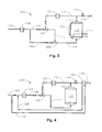
- FIGS. 1-5 are schematic process flow diagrams of embodiments of methods and systems described herein.
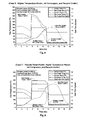
- FIGS. 6-9 are results of computer simulations showing temperature profiles for a comparative example system without the features of this disclosure and for three method embodiments within this disclosure, respectively, providing estimated temperatures for the inert gas (motive gas), recycle composition (compressor suction), and regeneration composition (compressor discharge) streams during the process cycle.
- inert gas motive gas
- recycle composition compressor suction
- regeneration composition compressor discharge
- FIGS. 1-5 are not to scale and illustrate only typical embodiments of this disclosure, and are therefore not to be considered limiting of its scope, for the disclosure may admit to other equally effective embodiments.
- Regeneration of the purification beds used in olefin polymerization processes requires a high flow of nitrogen or other heat transfer gas, but for a limited number of hours per year.
- the beds may either be reactive, in the sense that one or more chemical reactions between impurities and the bed material may occur in the beds as they are contacted with impure ethylene, propylene, or co-monomers such as butene, hexene, octene, and the like, or diluents such as ethane, propane, butane, iso-pentane, hexane, nitrogen, or non-reactive, where the impurities are adsorbed onto or into the bed material.
- the bed material is not a feature of this disclosure, but for example may be a copper complex, alumina complex, and the like.
- Two or more different bed materials may be placed in the same vessel, for example in stacked or co-mingled fashion. This may tend to reduce the total regeneration time and inert gas use versus separate vessels.
- high-purity nitrogen is used in the polymerization reactors downstream of the purification beds, some of the beds are used to purify nitrogen to remove water and oxygen, which are considered olefin catalyst poisons.
- a typical ethylene polymerization complex may include six vessels in ethylene purification service, two or three vessels in comonomer purification service, and two or three vessels in nitrogen purification service, some of which may be in parallel and some in series, so that some beds may be regenerated while the others are in purification service.
- the trend in the art is to use once-through nitrogen as an inert heating and cooling fluid that also delivers any regeneration gas and carries away the evolved impurities to the flare or other destruction device.
- the high absolute and peak nitrogen use and flaring increases operating and investment costs.
- This disclosure describes methods and systems for regenerating purification beds using an open-loop cycle, wherein a portion of the vessel effluent is recycled, and the remainder vented from the system, for example to a flare system.
- An inert gas (sometimes referred to herein as a motive gas, heat transfer fluid, or heat transfer gas) component is provided, wherein the inert gas component is supplied at a pressure above a pressure in the purification bed being regenerated.
- the inert gas may be supplied at a pressure at least two times, or at least three times, or at least four times, or more than four times the pressure of the pressure in the vessel containing the purification bed being regenerated.
- the inert gas pressure is advantageously at least two times the pressure in the vessel to be regenerated to provide adequate flow rate through the bed being regenerated. While pressure less than at least two times the regeneration pressure may be feasible, performance of the regeneration may suffer. On the other hand, using pressure higher than about four times the regeneration pressure does not significantly increase the performance of regeneration to justify the higher pressure inert gas. However, higher pressures may be used if desired.
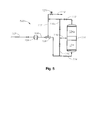
- FIGS. 1-5 are schematic process flow diagrams of five exemplary embodiments of methods and systems in accordance with this disclosure. Those skilled in the art will recognize alternatives to these embodiments after viewing the figures and reading the description herein, and these alternates are deemed to be within the scope of the present disclosure.
- Embodiment 100 illustrated schematically in FIG. 1 includes a supply conduit 102 for nitrogen or other inert gas. This is sometimes referred to herein as pipeline nitrogen, if nitrogen is the inert gas being used.
- Pipeline nitrogen is typically available at ambient temperature (about 20°C) and 100 psig (690 kPa) or higher pressure.
- Conduit 102 routes the inert gas first to a heater 104.
- Heater 104 may heat the gas in conduit 102 to a temperature of 200°C or higher.
- the energy added in heater 104 may be controlled to give a target temperature in the mixed regeneration gas stream of conduit 114.
- a conduit 106 then routes the heated inert gas to a jet compressor 108 (sometimes referred to as a thermal compressor or jet eductor), which serves to both mix the inert gas with a recycle stream in conduit 112 returning from vessel 110, and to increase the pressure of the recycle stream to a pressure that will allow the regeneration composition to pass through the bed being regenerated.
- a jet compressor 108 sometimes referred to as a thermal compressor or jet eductor
- the resulting regeneration composition passes through conduit 114 and into vessel 110 containing the material being regenerated.
- the regeneration composition in conduit 114 is approximately a weighted average of the compositions in conduits 106 and 112. Since evolved impurities are only a minor component of the recycle gas the mixed composition in conduit 114 is very close to the pipeline inert gas composition in conduit 106.
- the temperature at the outlet of jet compressor 108 in conduit 114 is essentially the weighted average of the temperature of the motive gas in conduit 106 and the temperature of the recycle gas in conduit 112.
- the motive gas temperature in conduit 106 is higher than the recycle gas temperature in conduit 112.
- the motive gas temperature in conduit 106 is lower than the recycle gas temperature in conduit 112.
- the pressure in conduit 114 will be higher than the pressure in the recycle conduit 112 by the pressure drop through the bed to be regenerated and the piping.
- the pressure in the motive gas conduit 106 needs to be at least 1.5 times the absolute pressure in conduit 114, and in exemplary embodiments at least 2 times the pressure in conduit 114.
- a higher ratio of the conduit 106 pressure to the conduit 114 pressure will allow a greater percentage of recycle gas from conduit 112 and less use of fresh motive gas from conduit 106 for the same flow rate in conduit 114.
- an effluent from vessel 110 exits through an effluent conduit 116.
- a portion of effluent in effluent conduit 116 is recycled via conduit 112, and a non-recycled portion is vented, for example routed to a flare system via conduit 118.
- a back-pressure control valve 120 may help regulate pressure in vessel 110 by balancing the venting in conduit 118 to match the fresh inert gas addition in conduit 106.
- the non-recycled portion maybe vented to the atmosphere as the inert gas is then free of hydrocarbons.
- FIG. 1 allows for the addition of additional purification vessels in parallel with vessel 110.
- the additional vessels may be regenerated simultaneously with vessel 110, or more commonly may be operating in their normal purification service, as shown with vessel 110a, while vessel 110 is regenerated.
- the gas or liquid to be purified is supplied via conduit 130, flows through one or more vessels 110a, and exists via conduit 132 for use in the manufacturing process.
- the solid-colored valves indicate that they are closed. After the regeneration cycle of vessel 110 is completed it can be returned to purification service and one of the other vessels regenerated using the same heater 104 and jet compressor 108 that were used with vessel 110, with closing and opening of appropriate valves.
- FIG. 2 illustrates one of a number of possible modifications of the method and system of FIG. 1 .
- Embodiment 200 considers a situation where two or more vessels 110, 110a,...110n (vessel 110n is not illustrated for brevity; n is a number) may contain the same or different beds to be regenerated. Most olefin polymerization facilities will have several different types and volumes of beds requiring regeneration from time to time. In these embodiments, while a single jet compressor may satisfy all requirements, in certain embodiments such as embodiment 200 a dedicated jet compressor 108, 108a, 108n (jet compressor 108n not illustrated for brevity) may be provided for each vessel 110, 110a, 110n or group of similar vessels with similar beds to be regenerated.
- a dedicated jet compressor 108, 108a, 108n jet compressor 108n not illustrated for brevity
- the jet compressors may be the same or different in terms of capacity, turn-down ratio, and other compression parameters.
- FIG. 2 illustrates conduits 106, 106a routing preheated pipeline nitrogen to jet compressors 108, 108a, to be combined with recycle streams flowing through conduits 112, 112a, to produce regeneration compositions routed through conduits 114, 114a to vessels 110, 110a.
- Effluent compositions from vessels 110, 110a exit the vessels through conduits 116, 116a, respectively, and a recycle portion from each vessel is routed through separate conduits 112, 112a to jet compressors 108, 108a, while non-recycled portions are routed through conduits 118, 118a to the flare system, pressure controlled by pressure regulators 120, 120a.
- One variation of embodiment 200 may be for separate conduits 102, 102a to route separate inert gas feeds to separate preheaters 104, 104a. In this way, should one preheater be out of service, the other may be used during regeneration of another bed or the heater size and location may be optimized for each vessel or group of similar vessels.
- FIG. 3 illustrates an embodiment 300 featuring other variations of methods and systems within the disclosure.
- Embodiment 300 features first and second jet compressors 108, 108a, in series flow arrangement.
- the compressors 108 and 108a may be the same or different in terms of compression capacity, materials of construction, and other operating and structural details.
- Compressor 108 may compress a mixture of inert gas and recycle composition from a pressure P1 and temperature T1 to a pressure P2, and temperature T2, where P1 and T1are the pressure and temperature, respectively, of the recycle composition in conduit 112, and P2 and T2 are the pressure and temperature, respectively, of the regeneration composition in conduit 113.
- Compressor 108a compresses the regeneration composition to a pressure P3 and temperature T3 in conduit 114, where P1 ⁇ P2 ⁇ P3.
- Heat exchanger 122 may be any type of heater, such as electric or steam, but in certain embodiments heat may be supplied in an indirect heat exchanger by a heat transfer fluid such as pressurized water or DOWTHERM.
- the addition of heat in exchanger 122 will decrease the required temperature in conduit 106 for the same regeneration gas temperature in conduit 114.
- heat exchanger 122 may be a cooler that uses air, water, or other fluid to cool the recycle flow in conduit 112. This cooling will lower the temperature in conduit 114 and so accelerate the cooling of the vessel 110 bed.
- FIG. 3 Two other optional features illustrated in FIG. 3 are the provision of a heat exchange jacket or heat exchange panel or panels 109, and a heat exchange coil or coils 111, either of which may be used for heating or cooling.
- the jacket or panel 109 and coil or coils 111 may either be electric, or employ a heat transfer fluid, such as water, steam, or glycol, or even a gas such as hydrogen, nitrogen, argon and mixtures thereof.
- FIG. 4 illustrates an embodiment 400 featuring yet another aspect of methods and systems of the present disclosure.
- a heat exchanger 124 and conduits 126, 128 are provided for preheating the inert gas in conduit 102 with the non-recycled portion of the vessel 110 effluent composition flowing through conduit 118.
- a variation of this embodiment may be to route a portion (or all) of the non-recycled effluent to a heat exchanger in conduit 102.
- Preheating of the gas to heater 104 may be advantageously applied during the heating portion of the regeneration cycle.
- the gas flow through conduit 126 would be stopped and cool inert gas would flow directly through conduit 102 to heater 104.
- the heating in heater 104 would also be shutoff during this cooling cycle so that the cool inert gas flows through conduit 106 to the jet compressor 108.
- FIG. 5 Another embodiment illustrated in FIG. 5 is where two or more beds are operated in series but arranged so that regeneration gas flow can be in series for some parts of the cycle and independent for other parts of the cycle.
- the beds may be in the same vessel as illustrated or in separate vessels. Examples where the arrangement of FIG. 5 might be advantageously used are where the beds have different target peak regeneration temperatures or one bed requires the addition of a secondary regeneration gas (such as hydrogen) for part of the cycle.
- a secondary regeneration gas such as hydrogen
- the initial heat up cycle might be for the hot gas from the jet compressor 108 to flow through conduit 114, up through bed 134, on up through bed 134a, then return to the jet compressor through conduits 116 and 112.
- the cycle could be switched so that continued heating of bed 134 may be performed by routing the gas through conduit 114, bed 134, conduit 136, conduit 116a, and conduit 112. This bypasses bed 134a.
- Part of the regeneration cycle could also pass the regeneration gas through conduit 114a, conduit 136, bed 134a, conduit 116, and conduit 112. This bypasses bed 134.
- FIGS. 1-5 various combinations of the features illustrated in FIGS. 1-5 may be employed, as will be apparent to those of skill in the art. These variations are considered within the scope of this disclosure.
- a conduit 140 and vessel 142 are indicated, representing some of the inert gas being routed to its own purification vessel or vessels, for example to remove water and oxygen.
- the purified inert gas is then routed to a polymerization reactor (not shown), perhaps via a booster compressor. In certain embodiments some of the purified inert gas may be used for regeneration of other beds, if desired.
- a representative regeneration cycle for methods and systems described herein will include an initial de-pressurization time period, where the vessel to be regenerated is vented, perhaps to a flare system.
- the vessel may then be purged with inert gas in order to remove interstitial hydrocarbons and other of the more easily removable impurities, followed by a warm-up time period, where one or more heaters available to (or in) the system are turned on. As explained more fully herein, this may include one or more programmed (or un-programmed) step changes in temperature.
- the vessel effluent may be vented to atmosphere, or a flare system during this step.
- the jet compressor 108 is bypassed during all or part of the cooling cycle with the hot gases from the vessel 110 vented via conduit 118.
- the jet compressor 108 is used to recycle a warm recycle stream 112 and mix it with the ambient temperature motive gas in conduit 106.
- the recycle in conduit 112 is pre-cooled in heat exchanger 122, as illustrated in FIG. 3 , in order to speed the cooling of vessel 110 without increasing the flow in conduit 106.
- FIG. 6 shows results of a computer simulation, showing the temperature profiles in a comparative example regeneration cycle without the use of one or more features of this disclosure.
- the profiles give estimated temperatures for the bed inlet (regeneration gas entering the bed) and the bed outlet (regeneration gas to vent).
- the profiles begin at the heating cycle and do not show the pressure reduction from operating pressure and the purge of the remaining interstitial gases or liquid.
- Inert gas for regeneration is assumed in this example to be heated at stepped intervals, say in three step intervals: 120°C, 300°C, and 30°C (assumed ambient).
- the bed outlet temperature increases as temperature of the vessel 110 increases, but with a lag time due to the thermal mass of the bed in vessel 110.
- the calculated mass of steel for the vessel containing the bed material was 32,340 lbs (14,670 kg) with a constant heat capacity of 0.11 Btu/1b-°F (460 J/kg-°K).
- an effective heat capacity was calculated to obtain a single heat capacity based on a weighted average of the bed material heat capacity and steel vessel heat capacity.
- the thermal mass heating was accomplished by separating the thermal mass into one inch (25.4 mm) layer increments and calculating the incremental heating of each thermal mass layer for each incremental time period.
- the rate of heat transfer within each thermal mass layer was calculated using a constant heat transfer factor of 0.0167 Btu/(min-lb-F) (69.8 J/(min-kg-C)).
- the heat transfer factor was empirically selected to provide simulated heating curves comparable to curves generated from actual operating data.
- the rate of heat transfer (HtRate) within each incremental thermal mass layer was calculated by multiplying the incremental thermal mass layer weight (SolWt) by the heat transfer factor (HTF) and by the temperature difference between the inlet gas temperature for the layer (InGasT) and the starting temperature of the thermal mass layer (SolStartT) (see Equation 1).
- the amount of heat transferred to the thermal mass layer (HtFlow) was found by multiplying the heat transfer rate by the incremental time period (Time) (see Equation 2).
- the final thermal mass layer temperature (SolEndT) was calculated by adding the starting thermal mass layer temperature (SolStartT) to the temperature increase of the thermal mass layer.
- the temperature increase of the thermal mass layer was calculated by dividing the amount heat transferred (HtFlow) by the thermal mass layer weight (SolWt) and by the thermal mass effective heat capacity (SolCp) (see Equation 3).
- the mass of regeneration composition in one time period was calculated by multiplying the gas rate (GasRate) by the incremental time period (Time) (see Equation 4).
- the outlet gas temperature was calculated by subtracting the inlet gas temperature of the thermal mass layer (InGasT) by the temperature loss of the gas through the thermal mass layer.
- the temperature loss of the gas through the thermal mass layer was calculated by dividing the amount heat transferred (HtFlow) by the mass of regeneration composition in one time period (GasFlow) and by the regeneration composition's heat capacity (GasCp) (see Equation 5).
- HtRate SolWt * HTF * InGasT - SolStartT
- a representative cycle requires a first stage where the bed is pre-heated using inlet regeneration gas with a temperature of 120° C (248° F). The pre-heat ends when the outlet temperature from the bed reaches 100° C (212° F). The regeneration gas inlet temperature to the bed is then increased to 300° C (572° F) and maintained there until the outlet temperature from the bed reaches 280° C (536° F). In these examples the regeneration gas heater is then shut off and the flow of ambient temperature regeneration gas gradually cools the bed to near the ambient temperature.
- the temperatures and number of steps are intended to be representative only and are not limiting of the teachings of this disclosure.
- the bed outlet temperature is observed to follow a smoothed curve due to the thermal mass of the bed and vessel. This is also why the peak bed outlet temperature occurs some time after the regeneration heater is turned off.
- the regeneration cycle is seen to take approximately 12 hours for the illustrated two step heat up cycle and approximately 7 hours for the cool down cycle.
- the total comparative example cycle uses 86,180 kg (189,990 Ib) of nitrogen based on a constant flow rate of 4,536 kg/h (10,000 Ib/hr).
- the regeneration heater added 10,580 MJ (2,940 kW h) of energy based on a simplifying assumption of no thermal losses to the environment.
- inert gas in conduit 102 may be heated at stepped intervals matching the regeneration gas steps of the FIG. 6 example.
- the recycle temperature increases as temperature of the vessel 110 increases, but with a lag time due to the thermal mass of the bed in vessel 110.
- the compressor discharge in stream 114 is essentially a weighted average of the temperatures of streams 106 and 112. This is illustrated graphically in FIG. 7 .
- another strategy (Case B) using a configuration as illustrated in FIG.
- inert gas temperature in conduit 106 is adjusted to obtain regeneration gas temperature (jet compressor discharge temperature) in conduit 114 at near step intervals, for example 30°C, 140°C, 300°C, with maximum inert gas (motive gas) temperature, in this case 450°C and with a cooler 122 being used to cool the recycle during the cool down stage.
- regeneration gas temperature jet compressor discharge temperature
- maximum inert gas (motive gas) temperature in this case 450°C
- a cooler 122 being used to cool the recycle during the cool down stage.
- This strategy is illustrated in FIG. 8 .
- exchanger 122 is used as a heater to increase the suction temperature during the heating cycle and as a cooler to decrease the suction temperature during the cooling cycle.
- Inert motive gas temperature is also varied during the heating cycle (see FIG. 9 ).
- FIGS. 7-9 show temperature profiles for the three simulated Cases A, B and C discussed in the previous paragraph.
- the profiles give estimated temperatures for the inert gas (motive), recycle (compressor suction) and regeneration composition (compressor discharge) streams during the process cycle.
- the compressor discharge stream temperature was determined using a thermodynamic balance around a jet compressor at each point.
- the temperature profiles may change from embodiment to embodiment, but provide an initial estimate for typical operating conditions expected for each case.
- Case A ( FIG. 7 ) is a very simple system that reduces the pipeline nitrogen flow rate. However, because of the cooling effect of the recycle stream the heat up time increased in this simulation to approximately 26 hours.
- the recycle gas temperature 112 slowly increased due to the thermal mass of the vessel 110 bed to be regenerated. Therefore, the regeneration composition (compressor discharge) 114 temperature also slowly increased.
- the warming effect of the thermal lag in the recycle gas increased the cool down cycle time to approximately 17 hours.
- Strategy C ( FIG. 9 ) used one or more recycle heat exchangers 122 as both a cooler and a heater to achieve a similar result. Adding heat to the recycle line via exchanger 122 allowed for a continuous hot recycle of stream 112 and so the regeneration gas 114 temperature was maintained at each target with less overshoot of the motive gas 106 temperature above the desired regeneration temperature. This provided a heat up time of approximately 12 hours but without the very high temperatures of Strategy B. Using exchanger 122 as a recycle cooler allowed the cool down to be done in approximately 7.5 hours as with Strategy B.
- compressor limitations may indicate more expensive materials of construction, such as special alloys (high chrome steel, or stainless steel, for example).
- special alloys high chrome steel, or stainless steel, for example.
- a single jet compressor may be designed to operate effectively during the thermal cycle, however this is not required. If this is desired, a jet compressor comprising materials of construction capable of withstanding the temperature changes and gradients during regeneration heating and cooling is necessary.
- each embodiment will likely determine after a short time how to achieve the highest efficiency (defined as the maximum inert gas recycle flow rate) without undue experimentation. This will primarily be obtained through adjustment of the various flow stream pressures, such as jet compressor suction and discharge pressures, as well as temperature changes observed for the various streams. Skilled operators and designers will be able to decide on the advantages/disadvantages of the various embodiments and options, for example, would a multiple jet compressor system provide more efficiency than a single jet compressor, and which system pressure has the most influence on the jet compressor efficiency (inert gas, recycle, or compressor discharge), and sizing of the jet compressor(s), and what operating variable is the system most sensitive to (pressure, temperature, velocity, mass flow).
- the maximum inert gas recycle flow rate defined as the maximum inert gas recycle flow rate
- Jet compressors are typically sold in a variety of frame sizes, and with various automatic control systems including a variable orifice for the motive gas inlet.
- the skilled compressor artisan will be able to decide what frame sizes and control systems are most beneficial for a particular regeneration scenario so as to produce the greatest amount of inert gas recycle.
- Typical automatic control strategies include feedback, feed-forward, cascade, and the like, and may be implemented via computer, either on-site or at a more centralized location. Proportional, integral, and differential control strategies may be employed, or combination thereof, such as PID controllers.
- a jet compressor designed with a fixed nozzle orifice or variable nozzle orifice could be used.
- the fixed nozzle orifice design with a fixed nozzle orifice area provides a constant motive flow rate at a constant motive gas pressure and temperature. Variations in the motive gas pressure and/or temperature will result in a change in motive gas flow rate.
- An example of a variable nozzle orifice design is a spindle with a needle point that moves in and out of the nozzle orifice throat in order to reduce the nozzle orifice flow area. The change in nozzle orifice flow area results in a change in the gas flow through the nozzle orifice at a given pressure and temperature.
- the control of the variable nozzle orifice spindle's position could be either manual or automatic. Jet compressors with manually controlled spindles are used when the unit operates at a steady load but where flexibility in nozzle orifice is desired to compensate for changes in operating conditions.
- the spindle can be operated with a handwheel or similar attachment. Jet compressors with automatically-controlled spindles are used where pressure, suction, or discharge conditions vary and it is necessary to control discharge pressure or flow.
- the spindle can be operated with a diaphragm, piston, or motor actuator using any standard instrument signal - electric or pneumatic.
- the illustrated embodiments could employ any these spindle control methods.
- the control can be activated by temperature, pressure, flow or suction to motive gas ratio.
- the illustrated embodiments could employ any these system variables for control.
- the inert gas used in the methods and systems described herein need not be completely devoid of reactant gases, as long as the regeneration of the purification bed proceeds in a safe and expeditious manner.
- the inert gas may be nitrogen, argon, krypton, xenon, carbon dioxide, or mixtures thereof, and may consist essentially of nitrogen purified from an air separation plant.
- the air separation plant may be selected from cryogenic, adsorption (pressure-swing, vacuum-swing, and temperature swing adsorption units are commercially available), and membrane separation plants.
- the inert gas is nitrogen, and the nitrogen may be electronic or food grade nitrogen.
- Pipeline nitrogen has the benefit of being at a pressure especially suited for use in a regeneration method, as it typically is already at or above the desired pressure, especially when the inert gas is used with a jet compressor to compress the recycle stream from the vessel containing the purification bed being regenerated.
- the inert gas component may advantageously be supplied via a pipeline at pipeline pressure in certain embodiments.
- nitrogen gas is typically transported down a pipeline under high pressure, typically 250 to 600 psig (1700 to 4100 kPa).
- the pressure for different systems will vary, but a pressure of 400 psig (2800 kPa) is a common pressure level seen in nitrogen pipelines.
- Current practice would have the nitrogen gas reduced in pressure through pressure regulator or regulators at a pressure letdown station to the customer's requirement, for example 150 psig (1000 kPa).
- nitrogen gas in stream 102 is substantially free of moisture and carbon dioxide, and has a nitrogen concentration greater than 99 volume percent, in certain embodiments greater than 99.9, or 99.99, or even 99.999 volume percent.
- the inert gas may be supplied by an inert gas generator, such as a membrane or adsorption unit. These units are well-known for producing "on-site” nitrogen. In such "on-site” nitrogen generators, one or more compressors are used to compress air at a pressure greater than atmospheric pressure, typically several bar of pressure or higher.
- the compressed air after filtration, water vapor removal, and possibly other operations known to the skilled artisan, is deliver as clean dry air containing, for example less than 1 ppm moisture (a dew point of 70°C or less), less than 0.01 micron particulates and no detectable residual oil vapor, to the feed side of a membrane unit which includes a membrane of, for example, polyimide, polyamide, polyolefin, or other glassy polymer.
- a nitrogen enriched gas mixture is withdrawn which comprises less than about 5 percent (by volume) oxygen, and on the permeate side of the membrane (preferably, but not necessarily, the bore side) an oxygen enriched gas mixture at ambient or lower pressure is vented.
- Adsorption-based systems may also be employed to supply inert gas.
- Known adsorption-based sources of nitrogen are a pressure-swing, vacuum-swing, and temperature swing adsorption units, which typically comprises two or more vessels containing an adsorbent material. When one adsorbent bed is "loaded", a control system switches or “swings" the feed air to the other vessel.
- an air compressor is used to compress air at a pressure which is preferably at least equal to about 10 bar, prior to being filtered (first stages include preferably a water separator, coalescing and particulate filters and an activated carbon tower).
- Such nitrogen generators may comprise an oxygen sensor and an oxygen monitoring system, in order to monitor the oxygen content of the "impure" nitrogen gas generated.
- a surge tank may be connected between (or in parallel to) the generator and the inert gas preheater wherein the pressure may be maintained greater than the normal pressure for use of the nitrogen, usually about 10 bar or even more.
- Appropriate membrane generators are for example those of the M 500 C. series of FLOXAL (a trademark of L'AIR LIQUIDE SA) Nitrogen membrane generators, as disclosed e.g. in the Tech Specs of such systems, incorporated therein by reference (those generators can usually provide nitrogen at different flow rates and different purities from about 95 volume percent inert gas to 99.5 volume percent inert gas).
- FLOXAL a trademark of L'AIR LIQUIDE SA
- Nitrogen membrane generators as disclosed e.g. in the Tech Specs of such systems, incorporated therein by reference (those generators can usually provide nitrogen at different flow rates and different purities from about 95 volume percent inert gas to 99.5 volume percent inert gas).
- Heat exchangers useful in the various embodiments may vary depending on the specific regeneration process. Although the various embodiments illustrated in the drawing figures may show a stream flowing through a shell and the other stream through a tube structure, the streams could be reversed. Also, where one exchanger unit is shown, it could as easily be two or more units in series or parallel.
- Useful heat exchangers may be shell-and-tube type, finned-tube, and the like. Flow arrangements may be counterflow, co-current flow, cross-flow, and the like.
- the heat exchangers may employ air, such as in a fan air cooler; water, such as supplied by a cooling tower; glycol; or via a refrigeration cycle. Combinations of these may be used. If the inert gas is nitrogen or argon supplied from a cryogenic air separation plant, it may be feasible to integrate a conduit carrying, for example, a recycle composition from a vessel being regenerated into the cold box of the cryogenic air separation unit.
- the inert or motive gas is heated (or cooled). This avoids the extra pressure drop in the recirculation system and since the heater/cooler only contacts relatively pure inert gas there is no coking risk.
- the temperature of the recycle stream was calculated by the simulation program in this simulation with a constant recycle pressure of 25 psig (172 kPA gauge), constant compressor discharge pressure of 35 psig (240 kPA gauge), and a constant motive gas pressure of 100 psig (690 kPA gauge).
- the simulation program calculated that the method and system as illustrated in FIG. 1 and FIG. 7 has a recirculation rate of 25 to 45 mass percent (i.e.
- ranges from any lower limit may be combined with any upper limit to recite a range not explicitly recited, as well as, ranges from any lower limit may be combined with any other lower limit to recite a range not explicitly recited, in the same way, ranges from any upper limit may be combined with any other upper limit to recite a range not explicitly recited.
Landscapes
- Chemical & Material Sciences (AREA)
- Organic Chemistry (AREA)
- Chemical Kinetics & Catalysis (AREA)
- Analytical Chemistry (AREA)
- Health & Medical Sciences (AREA)
- Thermal Sciences (AREA)
- Physics & Mathematics (AREA)
- Medicinal Chemistry (AREA)
- Polymers & Plastics (AREA)
- Separation Of Gases By Adsorption (AREA)
- Separation By Low-Temperature Treatments (AREA)
- Feeding, Discharge, Calcimining, Fusing, And Gas-Generation Devices (AREA)
- Cleaning In General (AREA)
- Gas Separation By Absorption (AREA)
Claims (22)
- Procédé pour régénérer un lit de purification contenu dans une cuve et utilisé lors d'un processus de polymérisation d'oléfine, le procédé utilisant un cycle à boucle ouverte dans lequel une partie d'un effluent provenant de la cuve est recyclée en tant que composition de recyclage, et le reste est évacué, le procédé comprenant les étapes consistant à :a) prévoir un gaz inerte à une première pression P1 ;b) combiner le gaz inerte avec la composition de recyclage de la cuve afin de former une composition de régénération à une deuxième pression P2, la composition de recyclage étant à une troisième pression P3 de sorte que P1 > P2 > P3 ; etc) acheminer la composition de régénération vers la cuve afin de régénérer le lit de purification.
- Procédé selon la revendication 1, dans lequel l'étape consistant à prévoir le gaz inerte comprend l'étape consistant à fournir le gaz inerte à une pression manométrique P1 qui représente au moins 1,5 fois la pression manométrique de la composition de régénération P2.
- Procédé selon la revendication 1, dans lequel l'étape consistant à prévoir le gaz inerte comprend l'étape consistant à fournir le gaz inerte à la pression manométrique P1 qui représente d'au moins deux fois à un maximum de quatre fois la pression manométrique P2 de la composition de régénération.
- Procédé selon l'une quelconque des revendications précédentes, dans lequel l'étape consistant à prévoir le gaz inerte comprend l'étape consistant à fournir le gaz inerte via une canalisation et P1 est la pression de canalisation.
- Procédé selon la revendication 4, dans lequel l'étape consistant à prévoir le gaz inerte comprend l'étape consistant à compléter l'alimentation de canalisation avec du gaz inerte généré par un générateur de gaz inerte sur site.
- Procédé selon l'une quelconque des revendications précédentes, dans lequel l'étape consistant à combiner le gaz inerte avec la composition de recyclage comprend l'étape consistant à combiner le gaz inerte et la composition de recyclage dans un compresseur à jet.
- Procédé selon l'une quelconque des revendications précédentes, dans lequel la composition de recyclage a un taux de recirculation qui est de l'ordre d'environ 20 à environ 80 pour cent en poids d'un écoulement total de gaz inerte et de composition de recyclage qui sont combinés.
- Procédé selon la revendication 7, dans lequel la partie non recyclée d'un effluent de cuve est acheminée vers un système de rebut.
- Procédé selon la revendication 8, dans lequel le gaz inerte est préchauffé par la partie non recyclée de l'effluent de cuve.
- Procédé selon l'une quelconque des revendications précédentes, dans lequel il y a une pluralité de lits de purification qui sont régénérés dans une pluralité correspondante de cuves.
- Procédé selon la revendication 10, dans lequel l'étape consistant à combiner le gaz inerte avec une composition de recyclage provenant de chaque cuve comprend l'étape consistant à combiner des courants de gaz inerte séparés avec un courant de recyclage correspondant provenant de chaque cuve.
- Procédé selon la revendication 11, dans lequel l'étape de combinaison a lieu dans un compresseur à jet dédié pour chaque combinaison de gaz interne avec une composition de recyclage.
- Procédé selon l'une quelconque des revendications précédentes, comprenant l'étape consistant à préchauffer le gaz inerte avant l'étape consistant à combiner le courant de recyclage.
- Procédé selon la revendication 13, dans lequel l'étape consistant à préchauffer le gaz inerte comprend les étapes consistant à chauffer le gaz inerte temporairement à une température supérieure à une température de composition de régénération cible, et ensuite au fur et à mesure que la température de la composition de recyclage augmente, diminuer la température du gaz inerte de sorte que la température de composition de régénération ne dépasse pas sa cible.
- Procédé selon l'une quelconque des revendications précédentes, comprenant en outre une étape choisie parmi l'étape consistant à chauffer la composition de recyclage avant l'étape consistant à la combiner avec le gaz inerte pendant un cycle de chauffage de lit et l'étape consistant à refroidir la composition de recyclage avant l'étape consistant à la combiner avec le gaz inerte dans un cycle de refroidissement de lit.
- Procédé selon la revendication 6, dans lequel deux compresseurs à jet ou plus sont utilisés en parallèle ou en série.
- Procédé selon l'une quelconque des revendications précédentes, dans lequel le procédé est utilisé pour réduire le volume des gaz de torchère produits à partir d'une installation de polymérisation d'oléfine.
- Système utilisé lors d'un processus de polymérisation d'oléfine pour régénérer un lit de purification contenu dans une cuve, le système utilisant un cycle à boucle ouverte, dans lequel une partie d'effluent de cuve est recyclée en tant que composition de recyclage, et le reste est évacué, et comprenant :a) une alimentation d'un gaz inerte à une première pression P1 ;b) l'alimentation de gaz inerte raccordée de manière fluide via un conduit à un compresseur à jet pour combiner le gaz inerte avec une composition de recyclage s'écoulant par un premier conduit raccordant de manière fluide le compresseur à jet et une cuve contenant un lit de purification qui est régénéré, le compresseur à jet formant une composition de régénération à une deuxième pression P2, la composition de recyclage à une troisième pression P3, de sorte que P1 > P2 > P3 ;c) un second conduit raccordant de manière fluide le compresseur à jet avec la cuve pour acheminer la composition de régénération vers la cuve afin de régénérer le lit de purification.
- Système selon la revendication 18, choisi parmi des systèmes comprenant une première unité d'échange de chaleur dans le conduit raccordant l'alimentation de gaz inerte au compresseur à jet, des systèmes comprenant une seconde unité d'échange de chaleur dans le premier conduit raccordant le compresseur à jet et la cuve, et leurs combinaisons.
- Système selon la revendication 18 ou 19, dans lequel le lit de purification comprend un premier lit de purification et un second lit de purification raccordé de manière fluide en série, les premier et second lits ayant les mêmes compositions de lit de purification respectives ou des compositions de lit de purification différentes.
- Système selon la revendication 20, dans lequel la cuve comprend une première et une seconde cuve, et le premier lit de purification se trouve dans la première cuve raccordée de manière fluide en série à la seconde cuve contenant le second lit de purification.
- Système selon la revendication 20, dans lequel le premier lit de purification se trouve dans un premier volume de la cuve et le second lit de purification se trouve dans un second volume de la cuve.
Applications Claiming Priority (2)
| Application Number | Priority Date | Filing Date | Title |
|---|---|---|---|
| US17244209P | 2009-04-24 | 2009-04-24 | |
| PCT/US2010/031199 WO2010123748A1 (fr) | 2009-04-24 | 2010-04-15 | Régénération de lits de purification avec un compresseur à jet dans un cycle à boucle ouverte |
Publications (2)
| Publication Number | Publication Date |
|---|---|
| EP2421902A1 EP2421902A1 (fr) | 2012-02-29 |
| EP2421902B1 true EP2421902B1 (fr) | 2014-12-17 |
Family
ID=42320045
Family Applications (1)
| Application Number | Title | Priority Date | Filing Date |
|---|---|---|---|
| EP10715420.5A Active EP2421902B1 (fr) | 2009-04-24 | 2010-04-15 | Régénération d'un lit de purification avec un compresseur à jet en boucle ouverte |
Country Status (7)
| Country | Link |
|---|---|
| US (1) | US8557029B2 (fr) |
| EP (1) | EP2421902B1 (fr) |
| CN (1) | CN102421804B (fr) |
| BR (1) | BRPI1015533A2 (fr) |
| MY (1) | MY161547A (fr) |
| RU (1) | RU2527452C2 (fr) |
| WO (1) | WO2010123748A1 (fr) |
Families Citing this family (18)
| Publication number | Priority date | Publication date | Assignee | Title |
|---|---|---|---|---|
| WO2012117325A1 (fr) * | 2011-03-03 | 2012-09-07 | Koninklijke Philips Electronics N.V. | Procédé et dispositif pour générer de l'oxygène |
| IN2014CN04797A (fr) * | 2011-12-28 | 2015-09-18 | Ineos Europe Ag | |
| EP2610002A1 (fr) | 2011-12-28 | 2013-07-03 | Ineos Europe AG | Interverrouillage |
| SG11201403684YA (en) | 2011-12-28 | 2014-07-30 | Ineos Europe Ag | Process |
| DE102013017123A1 (de) | 2013-10-15 | 2015-04-16 | Linde Aktiengesellschaft | Polymerisationsanlage mit Regeneriereinrichtung für adsorptive und /oder katalytische Reinigungseinrichtung, Regeneriereinrichtung und Regenerierverfahren |
| US9463434B2 (en) * | 2014-01-31 | 2016-10-11 | Spx Flow Technology Usa, Inc. | Heat reactivated adsorbent gas fractionator and process |
| EP3204468B1 (fr) | 2014-10-09 | 2020-07-29 | Basf Se | Procédé de régénération d'un adsorbant |
| SG11201702276YA (en) * | 2014-10-09 | 2017-04-27 | Basf Se | Heat exchange process for adsorber regeneration |
| US10894921B2 (en) | 2014-10-09 | 2021-01-19 | Basf Se | Product recovery process for adsorber regeneration |
| EA035034B1 (ru) * | 2014-10-09 | 2020-04-20 | Басф Се | Способ регенерации адсорбера |
| MY182513A (en) | 2014-10-09 | 2021-01-25 | Basf Se | Process for purification of an organic composition |
| BE1023062A1 (nl) * | 2015-05-13 | 2016-11-16 | Atlas Copco Airpower Nv | Inrichting voor het drogen van een samengeperst gas en compressorinstallatie voorzien van dergelijke inrichting. |
| JP6468995B2 (ja) * | 2015-12-10 | 2019-02-13 | Jfeスチール株式会社 | 圧力スイング吸着法によるガス分離方法及び設備 |
| CN108430916B (zh) * | 2016-01-15 | 2021-10-01 | 电子系统股份有限公司 | 氮气发生装置的电源控制装置 |
| EP3216511A1 (fr) * | 2016-03-08 | 2017-09-13 | Casale SA | Processus d'adsorption à oscillation de température |
| US11413570B2 (en) * | 2018-06-29 | 2022-08-16 | Munters Corporation | Rotary bed sorption system including recycled isolation loop and purge/regeneration loop |
| KR102898955B1 (ko) * | 2020-09-25 | 2025-12-10 | 에스케이이노베이션 주식회사 | 에틸렌-아크릴산 공중합체 제조 공정의 용매 세척방법 |
| WO2025136612A1 (fr) | 2023-12-20 | 2025-06-26 | ExxonMobil Technology and Engineering Company | Systèmes de lit de purification et procédés d'utilisation |
Family Cites Families (14)
| Publication number | Priority date | Publication date | Assignee | Title |
|---|---|---|---|---|
| BE671789A (fr) | 1964-11-20 | 1966-05-03 | Continental Oil Co | |
| US3733775A (en) * | 1971-07-14 | 1973-05-22 | Continental Oil Co | Adsorption process for recovering adsorbable components from a multi-component gas stream |
| DE2631225A1 (de) * | 1976-07-12 | 1978-01-26 | Adsorptionstech Lab | Regenerieren beladener adsorptionsmittel mit wasserdampf |
| US4331456A (en) * | 1979-06-08 | 1982-05-25 | John Zink Company | Process for recovering hydrocarbons with air-hydrocarbon vapor mixtures |
| US4424144A (en) | 1981-11-16 | 1984-01-03 | W. R. Grace & Co. | Preparation of binderless 3A adsorbents |
| FR2577148B1 (fr) | 1985-02-12 | 1987-04-30 | Traitement Gaz Genie Indl | Procede et dispositif pour la desorption de charbon actif |
| US4971606A (en) * | 1989-11-06 | 1990-11-20 | Air Products And Chemicals, Inc. | Closed-loop thermal regeneration of adsorbents containing reactive adsorbates |
| US5322927A (en) * | 1992-09-02 | 1994-06-21 | The Boc Group, Inc. | Method for producing polymers |
| US5312477A (en) * | 1993-02-23 | 1994-05-17 | M & W Industries | Adsorption/regeneration process |
| NO309487B1 (no) * | 1993-11-29 | 2001-02-05 | Boc Group Inc | Fremgangsmåte for gjenvinning av alken |
| BE1010132A3 (nl) * | 1996-04-02 | 1998-01-06 | Atlas Copco Airpower Nv | Werkwijze en inrichting voor het drogen van een door een compressor samengeperst gas. |
| WO2000074819A1 (fr) * | 1999-06-04 | 2000-12-14 | Flair Corporation | Systeme et procede d'adsorbeur a tambour rotatif |
| US6541412B1 (en) | 1999-12-10 | 2003-04-01 | Univation Technologies, Llc | Catalyst system method for preparing and using same in a polymerization process |
| JP2004504420A (ja) | 2000-07-17 | 2004-02-12 | ユニベーション・テクノロジーズ・エルエルシー | 触媒系及びその重合方法への使用 |
-
2010
- 2010-04-15 CN CN201080018216.0A patent/CN102421804B/zh active Active
- 2010-04-15 BR BRPI1015533A patent/BRPI1015533A2/pt not_active IP Right Cessation
- 2010-04-15 MY MYPI2011005102A patent/MY161547A/en unknown
- 2010-04-15 RU RU2011147501/04A patent/RU2527452C2/ru not_active IP Right Cessation
- 2010-04-15 US US13/257,339 patent/US8557029B2/en active Active
- 2010-04-15 EP EP10715420.5A patent/EP2421902B1/fr active Active
- 2010-04-15 WO PCT/US2010/031199 patent/WO2010123748A1/fr not_active Ceased
Also Published As
| Publication number | Publication date |
|---|---|
| US8557029B2 (en) | 2013-10-15 |
| MY161547A (en) | 2017-04-28 |
| WO2010123748A1 (fr) | 2010-10-28 |
| RU2527452C2 (ru) | 2014-08-27 |
| BRPI1015533A2 (pt) | 2018-01-16 |
| CN102421804B (zh) | 2014-10-15 |
| CN102421804A (zh) | 2012-04-18 |
| RU2011147501A (ru) | 2013-05-27 |
| EP2421902A1 (fr) | 2012-02-29 |
| US20120024324A1 (en) | 2012-02-02 |
Similar Documents
| Publication | Publication Date | Title |
|---|---|---|
| EP2421902B1 (fr) | Régénération d'un lit de purification avec un compresseur à jet en boucle ouverte | |
| RU2460573C2 (ru) | Усовершенствования в способах короткоцикловой адсорбции | |
| KR20230039696A (ko) | 가스 스트림으로부터 메탄 및 이산화탄소를 분리하기 위한 설비 및 막 프로세스 | |
| US6272882B1 (en) | Process of liquefying a gaseous, methane-rich feed to obtain liquefied natural gas | |
| US11623176B2 (en) | Nitrogen conservation in polymerization processes | |
| JP2023535134A5 (fr) | ||
| JPH0679124A (ja) | 精留されるべき空気の吸着による精製方法並びにその装置 | |
| PL206099B1 (pl) | Sposób i układ do usuwania dwutlenku węgla z gazu ziemnego, instalacja do przeprowadzania gazu ziemnego w stan ciekły, sposób wytwarzania ciekłego gazu ziemnego i wymiennik ciepła | |
| EP2440313A1 (fr) | Procédé et système pour récupérer du gaz à l'aide d'une membrane et d'une quantité réglable de pérméat recyclé combinée à une charge d'alimentation | |
| CN101573169A (zh) | 使用数个异阶段吸附器的纯化或者分离方法 | |
| US20050222476A1 (en) | Acetylene removal methods and apparatus | |
| KR20180044419A (ko) | 퍼지 가스로서 디메타나이저의 오버헤드 스트림을 사용하는 스윙 흡착 공정 및 시스템 | |
| KR20180048945A (ko) | 관련된 고속 순환 스윙 흡착 공정을 위한 장치 및 시스템 | |
| TWI873459B (zh) | 用於空氣分離之預淨化裝置及混合空氣淨化方法 | |
| KR102057024B1 (ko) | 퍼지 가스로서 디메타나이저의 오버헤드 스트림을 사용하는 스윙 흡착을 위한 공정 및 시스템 | |
| EP1951768B1 (fr) | Appareil et procede de production de copolymeres de polyethylene et d'ethylene | |
| CN108348835A (zh) | 用于处理天然气的再生筛材料 | |
| EP4335534B1 (fr) | Procédé et installation de séparation d'air | |
| WO2025101442A1 (fr) | Procédé de régulation pour procédé de transport d'hydrogène organique liquide | |
| JP2026040933A (ja) | 空気精製方法および空気精製装置 | |
| JP3195982B2 (ja) | 温度差再生式のガス吸着分離装置及び方法 | |
| KR20260005910A (ko) | 수증기 흡착을 사용하여 이산화탄소 포집을 최적화하는 시스템 및 방법 | |
| WO2024051962A1 (fr) | Procédé et installation de séparation d'air | |
| CN120351704A (zh) | 一种空分预冷热交换系统 | |
| JPH09229387A (ja) | 蒸気供給装置 |
Legal Events
| Date | Code | Title | Description |
|---|---|---|---|
| PUAI | Public reference made under article 153(3) epc to a published international application that has entered the european phase |
Free format text: ORIGINAL CODE: 0009012 |
|
| 17P | Request for examination filed |
Effective date: 20111031 |
|
| AK | Designated contracting states |
Kind code of ref document: A1 Designated state(s): AT BE BG CH CY CZ DE DK EE ES FI FR GB GR HR HU IE IS IT LI LT LU LV MC MK MT NL NO PL PT RO SE SI SK SM TR |
|
| DAX | Request for extension of the european patent (deleted) | ||
| GRAP | Despatch of communication of intention to grant a patent |
Free format text: ORIGINAL CODE: EPIDOSNIGR1 |
|
| INTG | Intention to grant announced |
Effective date: 20140703 |
|
| GRAS | Grant fee paid |
Free format text: ORIGINAL CODE: EPIDOSNIGR3 |
|
| GRAA | (expected) grant |
Free format text: ORIGINAL CODE: 0009210 |
|
| AK | Designated contracting states |
Kind code of ref document: B1 Designated state(s): AT BE BG CH CY CZ DE DK EE ES FI FR GB GR HR HU IE IS IT LI LT LU LV MC MK MT NL NO PL PT RO SE SI SK SM TR |
|
| REG | Reference to a national code |
Ref country code: GB Ref legal event code: FG4D |
|
| REG | Reference to a national code |
Ref country code: CH Ref legal event code: EP |
|
| REG | Reference to a national code |
Ref country code: IE Ref legal event code: FG4D |
|
| REG | Reference to a national code |
Ref country code: AT Ref legal event code: REF Ref document number: 701847 Country of ref document: AT Kind code of ref document: T Effective date: 20150115 |
|
| REG | Reference to a national code |
Ref country code: DE Ref legal event code: R096 Ref document number: 602010021041 Country of ref document: DE Effective date: 20150129 |
|
| PG25 | Lapsed in a contracting state [announced via postgrant information from national office to epo] |
Ref country code: NO Free format text: LAPSE BECAUSE OF FAILURE TO SUBMIT A TRANSLATION OF THE DESCRIPTION OR TO PAY THE FEE WITHIN THE PRESCRIBED TIME-LIMIT Effective date: 20150317 Ref country code: FI Free format text: LAPSE BECAUSE OF FAILURE TO SUBMIT A TRANSLATION OF THE DESCRIPTION OR TO PAY THE FEE WITHIN THE PRESCRIBED TIME-LIMIT Effective date: 20141217 Ref country code: LT Free format text: LAPSE BECAUSE OF FAILURE TO SUBMIT A TRANSLATION OF THE DESCRIPTION OR TO PAY THE FEE WITHIN THE PRESCRIBED TIME-LIMIT Effective date: 20141217 |
|
| REG | Reference to a national code |
Ref country code: LT Ref legal event code: MG4D |
|
| PG25 | Lapsed in a contracting state [announced via postgrant information from national office to epo] |
Ref country code: LV Free format text: LAPSE BECAUSE OF FAILURE TO SUBMIT A TRANSLATION OF THE DESCRIPTION OR TO PAY THE FEE WITHIN THE PRESCRIBED TIME-LIMIT Effective date: 20141217 Ref country code: HR Free format text: LAPSE BECAUSE OF FAILURE TO SUBMIT A TRANSLATION OF THE DESCRIPTION OR TO PAY THE FEE WITHIN THE PRESCRIBED TIME-LIMIT Effective date: 20141217 Ref country code: GR Free format text: LAPSE BECAUSE OF FAILURE TO SUBMIT A TRANSLATION OF THE DESCRIPTION OR TO PAY THE FEE WITHIN THE PRESCRIBED TIME-LIMIT Effective date: 20150318 Ref country code: SE Free format text: LAPSE BECAUSE OF FAILURE TO SUBMIT A TRANSLATION OF THE DESCRIPTION OR TO PAY THE FEE WITHIN THE PRESCRIBED TIME-LIMIT Effective date: 20141217 |
|
| REG | Reference to a national code |
Ref country code: AT Ref legal event code: MK05 Ref document number: 701847 Country of ref document: AT Kind code of ref document: T Effective date: 20141217 |
|
| PG25 | Lapsed in a contracting state [announced via postgrant information from national office to epo] |
Ref country code: NL Free format text: LAPSE BECAUSE OF FAILURE TO SUBMIT A TRANSLATION OF THE DESCRIPTION OR TO PAY THE FEE WITHIN THE PRESCRIBED TIME-LIMIT Effective date: 20141217 |
|
| PG25 | Lapsed in a contracting state [announced via postgrant information from national office to epo] |
Ref country code: RO Free format text: LAPSE BECAUSE OF FAILURE TO SUBMIT A TRANSLATION OF THE DESCRIPTION OR TO PAY THE FEE WITHIN THE PRESCRIBED TIME-LIMIT Effective date: 20141217 Ref country code: CZ Free format text: LAPSE BECAUSE OF FAILURE TO SUBMIT A TRANSLATION OF THE DESCRIPTION OR TO PAY THE FEE WITHIN THE PRESCRIBED TIME-LIMIT Effective date: 20141217 Ref country code: SK Free format text: LAPSE BECAUSE OF FAILURE TO SUBMIT A TRANSLATION OF THE DESCRIPTION OR TO PAY THE FEE WITHIN THE PRESCRIBED TIME-LIMIT Effective date: 20141217 Ref country code: EE Free format text: LAPSE BECAUSE OF FAILURE TO SUBMIT A TRANSLATION OF THE DESCRIPTION OR TO PAY THE FEE WITHIN THE PRESCRIBED TIME-LIMIT Effective date: 20141217 Ref country code: ES Free format text: LAPSE BECAUSE OF FAILURE TO SUBMIT A TRANSLATION OF THE DESCRIPTION OR TO PAY THE FEE WITHIN THE PRESCRIBED TIME-LIMIT Effective date: 20141217 |
|
| PG25 | Lapsed in a contracting state [announced via postgrant information from national office to epo] |
Ref country code: PL Free format text: LAPSE BECAUSE OF FAILURE TO SUBMIT A TRANSLATION OF THE DESCRIPTION OR TO PAY THE FEE WITHIN THE PRESCRIBED TIME-LIMIT Effective date: 20141217 Ref country code: IS Free format text: LAPSE BECAUSE OF FAILURE TO SUBMIT A TRANSLATION OF THE DESCRIPTION OR TO PAY THE FEE WITHIN THE PRESCRIBED TIME-LIMIT Effective date: 20150417 Ref country code: AT Free format text: LAPSE BECAUSE OF FAILURE TO SUBMIT A TRANSLATION OF THE DESCRIPTION OR TO PAY THE FEE WITHIN THE PRESCRIBED TIME-LIMIT Effective date: 20141217 |
|
| REG | Reference to a national code |
Ref country code: DE Ref legal event code: R097 Ref document number: 602010021041 Country of ref document: DE |
|
| PLBE | No opposition filed within time limit |
Free format text: ORIGINAL CODE: 0009261 |
|
| STAA | Information on the status of an ep patent application or granted ep patent |
Free format text: STATUS: NO OPPOSITION FILED WITHIN TIME LIMIT |
|
| PG25 | Lapsed in a contracting state [announced via postgrant information from national office to epo] |
Ref country code: DK Free format text: LAPSE BECAUSE OF FAILURE TO SUBMIT A TRANSLATION OF THE DESCRIPTION OR TO PAY THE FEE WITHIN THE PRESCRIBED TIME-LIMIT Effective date: 20141217 |
|
| 26N | No opposition filed |
Effective date: 20150918 |
|
| PG25 | Lapsed in a contracting state [announced via postgrant information from national office to epo] |
Ref country code: LU Free format text: LAPSE BECAUSE OF FAILURE TO SUBMIT A TRANSLATION OF THE DESCRIPTION OR TO PAY THE FEE WITHIN THE PRESCRIBED TIME-LIMIT Effective date: 20150415 Ref country code: MC Free format text: LAPSE BECAUSE OF FAILURE TO SUBMIT A TRANSLATION OF THE DESCRIPTION OR TO PAY THE FEE WITHIN THE PRESCRIBED TIME-LIMIT Effective date: 20141217 |
|
| REG | Reference to a national code |
Ref country code: CH Ref legal event code: PL |
|
| PG25 | Lapsed in a contracting state [announced via postgrant information from national office to epo] |
Ref country code: IT Free format text: LAPSE BECAUSE OF FAILURE TO SUBMIT A TRANSLATION OF THE DESCRIPTION OR TO PAY THE FEE WITHIN THE PRESCRIBED TIME-LIMIT Effective date: 20141217 |
|
| REG | Reference to a national code |
Ref country code: IE Ref legal event code: MM4A |
|
| PG25 | Lapsed in a contracting state [announced via postgrant information from national office to epo] |
Ref country code: LI Free format text: LAPSE BECAUSE OF NON-PAYMENT OF DUE FEES Effective date: 20150430 Ref country code: CH Free format text: LAPSE BECAUSE OF NON-PAYMENT OF DUE FEES Effective date: 20150430 |
|
| PG25 | Lapsed in a contracting state [announced via postgrant information from national office to epo] |
Ref country code: SI Free format text: LAPSE BECAUSE OF FAILURE TO SUBMIT A TRANSLATION OF THE DESCRIPTION OR TO PAY THE FEE WITHIN THE PRESCRIBED TIME-LIMIT Effective date: 20141217 |
|
| REG | Reference to a national code |
Ref country code: FR Ref legal event code: PLFP Year of fee payment: 7 |
|
| PG25 | Lapsed in a contracting state [announced via postgrant information from national office to epo] |
Ref country code: IE Free format text: LAPSE BECAUSE OF NON-PAYMENT OF DUE FEES Effective date: 20150415 |
|
| PG25 | Lapsed in a contracting state [announced via postgrant information from national office to epo] |
Ref country code: BE Free format text: LAPSE BECAUSE OF FAILURE TO SUBMIT A TRANSLATION OF THE DESCRIPTION OR TO PAY THE FEE WITHIN THE PRESCRIBED TIME-LIMIT Effective date: 20141217 |
|
| PG25 | Lapsed in a contracting state [announced via postgrant information from national office to epo] |
Ref country code: MT Free format text: LAPSE BECAUSE OF FAILURE TO SUBMIT A TRANSLATION OF THE DESCRIPTION OR TO PAY THE FEE WITHIN THE PRESCRIBED TIME-LIMIT Effective date: 20141217 |
|
| REG | Reference to a national code |
Ref country code: FR Ref legal event code: PLFP Year of fee payment: 8 |
|
| PG25 | Lapsed in a contracting state [announced via postgrant information from national office to epo] |
Ref country code: HU Free format text: LAPSE BECAUSE OF FAILURE TO SUBMIT A TRANSLATION OF THE DESCRIPTION OR TO PAY THE FEE WITHIN THE PRESCRIBED TIME-LIMIT; INVALID AB INITIO Effective date: 20100415 Ref country code: SM Free format text: LAPSE BECAUSE OF FAILURE TO SUBMIT A TRANSLATION OF THE DESCRIPTION OR TO PAY THE FEE WITHIN THE PRESCRIBED TIME-LIMIT Effective date: 20141217 Ref country code: BG Free format text: LAPSE BECAUSE OF FAILURE TO SUBMIT A TRANSLATION OF THE DESCRIPTION OR TO PAY THE FEE WITHIN THE PRESCRIBED TIME-LIMIT Effective date: 20141217 |
|
| PG25 | Lapsed in a contracting state [announced via postgrant information from national office to epo] |
Ref country code: CY Free format text: LAPSE BECAUSE OF FAILURE TO SUBMIT A TRANSLATION OF THE DESCRIPTION OR TO PAY THE FEE WITHIN THE PRESCRIBED TIME-LIMIT Effective date: 20141217 |
|
| PG25 | Lapsed in a contracting state [announced via postgrant information from national office to epo] |
Ref country code: PT Free format text: LAPSE BECAUSE OF FAILURE TO SUBMIT A TRANSLATION OF THE DESCRIPTION OR TO PAY THE FEE WITHIN THE PRESCRIBED TIME-LIMIT Effective date: 20150417 |
|
| PG25 | Lapsed in a contracting state [announced via postgrant information from national office to epo] |
Ref country code: TR Free format text: LAPSE BECAUSE OF FAILURE TO SUBMIT A TRANSLATION OF THE DESCRIPTION OR TO PAY THE FEE WITHIN THE PRESCRIBED TIME-LIMIT Effective date: 20141217 |
|
| REG | Reference to a national code |
Ref country code: FR Ref legal event code: PLFP Year of fee payment: 9 |
|
| PG25 | Lapsed in a contracting state [announced via postgrant information from national office to epo] |
Ref country code: MK Free format text: LAPSE BECAUSE OF FAILURE TO SUBMIT A TRANSLATION OF THE DESCRIPTION OR TO PAY THE FEE WITHIN THE PRESCRIBED TIME-LIMIT Effective date: 20141217 |
|
| REG | Reference to a national code |
Ref country code: DE Ref legal event code: R082 Ref document number: 602010021041 Country of ref document: DE Representative=s name: KILBURN & STRODE LLP, NL |
|
| P01 | Opt-out of the competence of the unified patent court (upc) registered |
Effective date: 20230525 |
|
| PGFP | Annual fee paid to national office [announced via postgrant information from national office to epo] |
Ref country code: FR Payment date: 20250310 Year of fee payment: 16 |
|
| PGFP | Annual fee paid to national office [announced via postgrant information from national office to epo] |
Ref country code: GB Payment date: 20250306 Year of fee payment: 16 |
|
| PGFP | Annual fee paid to national office [announced via postgrant information from national office to epo] |
Ref country code: DE Payment date: 20250305 Year of fee payment: 16 |