EP2422937A2 - Robotersystem - Google Patents
Robotersystem Download PDFInfo
- Publication number
- EP2422937A2 EP2422937A2 EP11179416A EP11179416A EP2422937A2 EP 2422937 A2 EP2422937 A2 EP 2422937A2 EP 11179416 A EP11179416 A EP 11179416A EP 11179416 A EP11179416 A EP 11179416A EP 2422937 A2 EP2422937 A2 EP 2422937A2
- Authority
- EP
- European Patent Office
- Prior art keywords
- workpiece
- workpieces
- manipulator
- assortment
- boxes
- Prior art date
- Legal status (The legal status is an assumption and is not a legal conclusion. Google has not performed a legal analysis and makes no representation as to the accuracy of the status listed.)
- Withdrawn
Links
Images







Classifications
-
- B—PERFORMING OPERATIONS; TRANSPORTING
- B25—HAND TOOLS; PORTABLE POWER-DRIVEN TOOLS; MANIPULATORS
- B25J—MANIPULATORS; CHAMBERS PROVIDED WITH MANIPULATION DEVICES
- B25J13/00—Controls for manipulators
- B25J13/08—Controls for manipulators by means of sensing devices, e.g. viewing or touching devices
-
- B—PERFORMING OPERATIONS; TRANSPORTING
- B25—HAND TOOLS; PORTABLE POWER-DRIVEN TOOLS; MANIPULATORS
- B25J—MANIPULATORS; CHAMBERS PROVIDED WITH MANIPULATION DEVICES
- B25J9/00—Program-controlled manipulators
- B25J9/16—Program controls
- B25J9/1694—Program controls characterised by use of sensors other than normal servo-feedback from position, speed or acceleration sensors, perception control, multi-sensor controlled systems, sensor fusion
- B25J9/1697—Vision controlled systems
-
- B—PERFORMING OPERATIONS; TRANSPORTING
- B25—HAND TOOLS; PORTABLE POWER-DRIVEN TOOLS; MANIPULATORS
- B25J—MANIPULATORS; CHAMBERS PROVIDED WITH MANIPULATION DEVICES
- B25J9/00—Program-controlled manipulators
- B25J9/16—Program controls
- B25J9/1679—Program controls characterised by the tasks executed
- B25J9/1682—Dual arm manipulator; Coordination of several manipulators
-
- G—PHYSICS
- G05—CONTROLLING; REGULATING
- G05B—CONTROL OR REGULATING SYSTEMS IN GENERAL; FUNCTIONAL ELEMENTS OF SUCH SYSTEMS; MONITORING OR TESTING ARRANGEMENTS FOR SUCH SYSTEMS OR ELEMENTS
- G05B19/00—Program-control systems
- G05B19/02—Program-control systems electric
- G05B19/18—Numerical control [NC], i.e. automatically operating machines, in particular machine tools, e.g. in a manufacturing environment, so as to execute positioning, movement or co-ordinated operations by means of program data in numerical form
- G05B19/4093—Numerical control [NC], i.e. automatically operating machines, in particular machine tools, e.g. in a manufacturing environment, so as to execute positioning, movement or co-ordinated operations by means of program data in numerical form characterised by part programming, e.g. entry of geometrical information as taken from a technical drawing, combining this with machining and material information to obtain control information, named part program, for the NC machine
-
- G—PHYSICS
- G06—COMPUTING OR CALCULATING; COUNTING
- G06T—IMAGE DATA PROCESSING OR GENERATION, IN GENERAL
- G06T7/00—Image analysis
-
- G—PHYSICS
- G05—CONTROLLING; REGULATING
- G05B—CONTROL OR REGULATING SYSTEMS IN GENERAL; FUNCTIONAL ELEMENTS OF SUCH SYSTEMS; MONITORING OR TESTING ARRANGEMENTS FOR SUCH SYSTEMS OR ELEMENTS
- G05B2219/00—Program-control systems
- G05B2219/30—Nc systems
- G05B2219/39—Robotics, robotics to robotics hand
- G05B2219/39109—Dual arm, multiarm manipulation, object handled in cooperation
-
- G—PHYSICS
- G05—CONTROLLING; REGULATING
- G05B—CONTROL OR REGULATING SYSTEMS IN GENERAL; FUNCTIONAL ELEMENTS OF SUCH SYSTEMS; MONITORING OR TESTING ARRANGEMENTS FOR SUCH SYSTEMS OR ELEMENTS
- G05B2219/00—Program-control systems
- G05B2219/30—Nc systems
- G05B2219/40—Robotics, robotics mapping to robotics vision
- G05B2219/40053—Pick 3-D object from pile of objects
-
- Y—GENERAL TAGGING OF NEW TECHNOLOGICAL DEVELOPMENTS; GENERAL TAGGING OF CROSS-SECTIONAL TECHNOLOGIES SPANNING OVER SEVERAL SECTIONS OF THE IPC; TECHNICAL SUBJECTS COVERED BY FORMER USPC CROSS-REFERENCE ART COLLECTIONS [XRACs] AND DIGESTS
- Y10—TECHNICAL SUBJECTS COVERED BY FORMER USPC
- Y10S—TECHNICAL SUBJECTS COVERED BY FORMER USPC CROSS-REFERENCE ART COLLECTIONS [XRACs] AND DIGESTS
- Y10S901/00—Robots
- Y10S901/30—End effector
Definitions
- the present invention relates to a robot system.
- a robot system comprising: a manipulator; a work table arranged within a movement extent of the manipulator; an imaging unit for taking a two-dimensional image of workpieces loaded on the work table; a workpiece supply unit for supplying the workpieces onto the work table; and a control system for controlling operations of the manipulator and the imaging unit.
- the control system includes an imaging control unit for controlling the imaging unit to take the two-dimensional image of the workpieces loaded on the work table when the workpieces are supplied onto the work table by the workpiece supply unit, a workpiece detecting unit for detecting a position and a posture of each of the workpieces loaded on the work table by comparing the two-dimensional image taken by the imaging unit with templates stored in advance, and a manipulator control unit for operating the manipulator to perform a work with respect to the workpieces detected by the workpiece detecting unit.
- an imaging control unit for controlling the imaging unit to take the two-dimensional image of the workpieces loaded on the work table when the workpieces are supplied onto the work table by the workpiece supply unit
- a workpiece detecting unit for detecting a position and a posture of each of the workpieces loaded on the work table by comparing the two-dimensional image taken by the imaging unit with templates stored in advance
- a manipulator control unit for operating the manipulator to perform a work with respect to the workpieces detected by the workpiece
- the work performed by the manipulator may be a transfer work in which a predetermined number of bolts are gripped and transferred by the manipulator.
- the manipulator control unit may repeatedly perform, after finishing the transfer work of the workpieces detected by the workpiece detecting unit, an operation of supplying the workpieces onto the work table through the use of the workpiece supply unit and an operation of transferring the workpieces detected by the workpiece detecting unit through the use of the imaging control unit and the workpiece detecting unit until the number of transferred workpieces reaches the predetermined number of workpieces.
- the manipulator may be a double-arm manipulator including a swiveling body and first and second arms provided to the body, the double-arm manipulator serving as the workpiece supply unit.
- the robot system further includes a workpiece rack for storing a plurality of workpiece boxes in which a plurality of workpieces is accommodated on a kind-by-kind basis; a raking tool for raking out the workpieces from each of the workpiece boxes; and an assortment table for supporting an assortment box divided into a plurality of compartments.
- the double-arm manipulator further includes a first hand provided at a tip end of the first arm through a first force sensor and a second hand provided at a tip end of the second arm through a second force sensor, the first hand having a first gripping unit for gripping one of the workpieces and a tool holder for holding the raking tool, and the second hand having a second gripping unit for gripping one of the workpiece boxes.
- the double-arm manipulator is configured to perform an operation of gripping one of the workpiece boxes with the second gripping unit and taking out one of the workpiece boxes from the workpiece rack, an operation of raking out the workpieces from one of the workpiece boxes onto the work table with the raking tool held by the tool holder and an operation of gripping one of the workpieces on the work table with the first gripping unit and transferring the gripped workpiece to one of the compartments of the assortment box.
- the operation of raking out the workpieces may be performed by putting the raking tool into one of the workpiece boxes, moving the raking tool downwards by a predetermined depth from a position in which the first force sensor shows a change in output value, raking out the workpieces from one of the workpiece boxes, moving the raking tool downwards by a depth greater than the predetermined depth if a predetermined number of workpieces are not raked out, and raking out the workpieces from one of the workpiece boxes once again.
- the predetermined number of workpieces may be found depending on an output value of the second force sensor.
- the assortment table, the work table and the workpiece rack may be arranged along a circle about a rotation axis of the body of the double-arm manipulator.
- the assortment box may include an information storage medium storing information on the kind and number of the workpieces accommodated in the compartments of the assortment box.
- a part picking system(robot system) includes a work device 9, an assortment table 13, a raking tool 15 and a plurality of workpiece racks 20.
- the work device 9 includes a double-arm manipulator (one example of a manipulator and a workpiece supply unit) 11, a work table 17, a two-dimensional camera (one example of an imaging unit) 100 and a control system 150.
- the control system 150 includes a robot controller 22, a system controller 24 and an image processing computer 26. While the control system 150 of the present embodiment includes three individual operation units, i.e., the robot controller 22, the system controller 24 and the image processing computer 26, the number of the operation units making up the control system 150 may be arbitrarily changed.
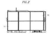
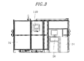
- the picking system 10 is capable of taking out a required number of specific bolts (one example of workpiece s) from the workpiece racks 20 and bringing them into assortment boxes B1 loaded on a conveying carriage 12. As shown in Fig. 1 through 3 , the picking system 10 is surrounded by a protective wall 31 having a sliding door 30 arranged in a gateway.
- the double-arm manipulator 11 includes a left arm (one example of a first arm) 11a and a right arm (one example of a second arm) 11b, both of which are arranged at the left and right sides of the swiveling body 11c.
- Each of the left arm 11a and the right arm 11b is a multi-joint manipulator having, e.g., seven joint axes.
- the gripping claws 36 can be moved toward and away from each other along the picking axis AXp.
- the gripping claws 36 are driven by a servo motor (not shown) so that the bolt gripping force thereof can be controlled.
- the tool holding members 41 are provided in the support portions 42 for supporting the gripping claws 36. This means that the tool holding members 41 are moved toward and away from each other in concert with that of the gripping claws 36.
- the right arm 11b has a wrist flange 32b at a leading end thereof, and a right hand (one example of a second hand) 35b is coupled to the wrist flange 32b through a right force sensor (one example of a second force sensor) 33b.
- the right hand 35b is capable of gripping a workpiece box B2 having the bolts therein.
- the right hand 35b includes lower and upper gripping claws (one example of a second gripping unit) 44 for gripping the rear portion of the workpiece box B2 vertically interposed therebetween.
- the lower gripping claw 44 is configured to support a bottom surface of the workpiece box B2.
- the upper gripping claw 44 is configured to move toward and away from the lower gripping claw 44 along an opening/closing axis AXq orthogonal to a rotation axis AXtb of the wrist flange 32b.
- the upper gripping claw 44 is moved to contact with the lower gripping claw 44 in Fig. 5 .
- the left force sensor 33a and the right force sensor 33b are connected to the system controller 24 through the robot controller 22.
- the conveying carriage 12 is capable of conveying the assortment boxes B1 for receiving the bolts gripped by the double-arm manipulator 11.
- the conveying carriage 12 includes a carriage frame 50 and a rotary table 51 supported by the carriage frame 50, the rotary table being capable of rotating about a vertical axis AX3.
- Casters (not shown) are attached to the lower portion of the carriage frame 50.
- An angle calculation unit (not shown) for calculating the rotation angle of the rotary table 51 and a fixing unit (not shown) for fixing the rotary table 51 at a specified angular position are provided in the carriage frame 50.
- the rotary table 51 includes a circular top plate 52 capable of supporting a plurality of assortment boxes B1 arranged at, e.g., five places, along the circumference thereof.
- the horizontal positions of the assortment boxes B1 are determined by a plurality of guide poles 54 extending upwards from the top plate 52.
- the assortment boxes B1 may be stacked one above another up to, e.g., ten stories.
- Each of the assortment boxes B1 is divided into a plurality of compartments (e.g., four compartments like the assortment box B1 loaded onto the assortment table 13) and is provided with handles 56 on the left and right side surfaces thereof.
- Each of the assortment boxes B1 includes an upwardly openable lid 58 pivotably held by a hinge 57 provided on the rear surface thereof.
- the lid 58 is provided with a forwardly protruding knob 59.
- the assortment boxes B1 are made of, e.g., resin. Different kinds of bolts are accommodated within the respective compartments of each of the assortment boxes B1.
- Attached to the rear surface of each of the assortment boxes B1 is a two-dimensional barcode (one example of an information storage medium) for storing at least first matching information in which each compartment of the assortment box B1 is matched with the corresponding kind (e.g., the diameter, length and material) and the number of the bolts to be put into the corresponding compartment.
- the two-dimensional barcode may be substituted by a one-dimensional barcode. Since the two-dimensional barcode storing the first matching information is directly attached to each of the assortment boxes B1, the correspondence between the assortment boxes B1 and the bolts to be put into the assortment boxes B1 becomes clear.
- the conveying carriage 12 is provided with a bar 63 so that a worker can hold the bar 63 and move the conveying carriage 12.
- the conveying carriage 12 loaded with the assortment boxes B1 is carried in and out by the worker through the gateway provided with the sliding door 30. If the conveying carriage 12 is carried into a specified position, it is lifted up by an air cylinder (not shown) and, consequently, fixed in place with the casters kept spaced apart from the floor.
- the assortment table 13 is a table for holding one of the assortment boxes B1 unloaded from the conveying carriage 12 by the double-arm manipulator 11.
- the bolts taken out from the workpiece box B2 on each of the workpiece racks 20 by the double-arm manipulator 11 are transferred to the assortment box B1 placed on the assortment table 13 (one example of a work).
- the raking tool 15 is a tool used for the double-arm manipulator 11 to rake out the bolts from the workpiece box B2 onto the work table 17.
- the raking tool 15 includes a handle 72 and a plurality of raking forks 73 provided at the tip end of the handle 72.
- the raking forks 73 are formed of a plurality of metal prongs extending from the proximal ends toward the distal ends in a curved shape.
- An adapter (not shown) for enabling the tool holder 41 of the left hand 35a to hold the raking tool 15 is attached to the handle 72.
- the raking tool 15 is placed on a stand 75.
- the work table 17 is a table arranged within the movement extent of the double-arm manipulator 11 so that the double-arm manipulator 11 can grip the bolts raked out from the workpiece box B2.
- the work table 17 includes a tiltable plate 80 for receiving the raked-out bolts and a workpiece box stand 90 for temporarily supporting the workpiece box B2.
- the tiltable plate 80 is formed of, e.g., a rectangular plate.
- the tiltable plate 80 is pivotable about a rotation axis AX4 that extends substantially horizontal the ground and orthogonal to the longitudinal direction of the tiltable plate 80 at one end portion of the tiltable plate 80.
- the workpiece box stand 90 is arranged next to a side of the tiltable plate 80 where the rotation axis AX4 exists.
- the tiltable plate 80 is tilted about the rotation axis AX4 so that the bolts on the tiltable plate 80 can be brought back to the workpiece box B2 temporarily placed on the workpiece box stand 90.
- the workpiece box stand 90 is provided with a load sensor (not shown) for detecting the workpiece box B2 placed thereon.
- a two-dimensional camera 100 is provided above the tiltable plate 80 to take a two-dimensional image of the bolts placed on the work table 17.
- the two-dimensional camera 100 may be, e.g., a two-dimensional monochromatic camera with 4 million pixels.
- the two-dimensional camera 100 is supported by a stand 105 in a height-adjustable manner.
- An illumination device 101 for securing illuminance required for the two-dimensional camera 100 to take an image is provided in the stand 105.
- the two-dimensional camera 100 is connected to the image processing computer 26.
- the image taken by the two-dimensional camera 100 is transmitted to the image processing computer 26.
- the two-dimensional camera 100 is also connected to the system controller 24 so that the imaging operation of the two-dimensional camera 100 can be controlled by the system controller 24.
- the system controller 24 is configured to serve as an imaging control unit for controlling the two-dimensional camera 100.
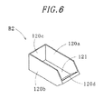
- the workpiece box B2 includes a rectangular bottom plate 121, left and right side plates 120a and 120b extending upwards from the left and right edges of the bottom plate 121, a rear plate 120c extending upwards from the rear edge of the bottom plate 121 and a front plate 120d obliquely extending forwards from the front edge of the bottom plate 121.
- the height of the front plate 120d measured from the front edge of the bottom plate 121 to the tip end of the front plate 120d is shorter than the height of the left and right side plates 120a and 120b and the rear plate 120c.
- the workpiece box B2 is opened at the top end and the front upper side thereof. As will be described in detail, the bolts are raked out from the front side of the workpiece box B2 by the double-arm manipulator 11.
- Each of the workpiece racks 20 is divided into, e.g., two-row five-story compartments. workpiece boxes B2 holding different kinds of bolts are stored in the respective compartments. In case where each of the workpiece racks 20 has two-row five-story compartments as mentioned above, the picking system 10 including six workpiece racks 20 can store sixty kinds of bolts in total.
- the workpiece boxes B2 are stored so that the rear surface of each of the workpiece boxes B2 can face the double-arm manipulator 11 with the front surface thereof facing toward the outside of the workpiece picking system 10.
- the system controller 24 stores in advance second matching information indicating the kinds of bolts of the workpiece boxes B2 stored in the respective compartments.
- operation teaching data of the double-arm manipulator 11 containing the positions of the respective compartments are stored in the robot controller 22.
- a barcode (or a two-dimensional barcode) containing the information on the kinds of bolts is attached to each of the workpiece boxes B2 stored in the workpiece racks 20.
- the double-arm manipulator 11 causes the barcode reader provided in the assortment table 13 to read the barcode of each of the workpiece boxes B2.
- the double-arm manipulator 11 stores the workpiece boxes B2 within the respective compartments of the workpiece racks 20.
- the information on the barcodes allotted to the workpiece boxes B2 (the information indicating at least the kinds of bolts) is matched with each of the compartments and is stored in the system controller 24 as the second matching information.
- each of the workpiece racks 20 there is provided a lamp (not shown) for indicating that the number of bolts contained in each of the workpiece boxes B2 is smaller than a predetermined number. If the lamp is turned on, the worker may take out the workpiece box B2 at issue from the rear side of each of the workpiece racks 20 and may supplement the workpiece box B2 with new bolts.
- the robot controller 22 is provided as one example of a manipulator control unit.
- the robot controller 22 is connected to the double-arm manipulator 11 to control the operation of the double-arm manipulator 11.
- the system controller 24 is connected to the robot controller 22 to control the overall operation of the picking system 10.
- the system controller 24 can control the on/off operations of the lamps set forth above.
- the worker can operate the system controller 24 through the use of a touch panel 110 (see Fig. 3 ).
- the system controller 24 includes, e.g., a programmable logic controller.
- the image processing computer 26 is provided as one example of a workpiece detector unit.
- the image processing computer 26 is connected to the two-dimensional camera 100 and the system controller 24 and is essentially capable of processing the images taken by the two-dimensional camera 100.
- the bolt picking method is largely composed of steps S1 through S4.
- step S1 the double-arm manipulator 11 brings one of the assortment boxes B1 from the conveying carriage 12 to the assortment table 13.
- step S2 the double-arm manipulator 11 transfers the bolts from each of the workpiece racks 20 to the assortment box B1.
- step S3 the double-arm manipulator 11 returns the assortment box B1 containing the bolts to the conveying carriage 12.
- step S4 determination is made as to whether to stop the operations. Steps S1 through S4 will now be described one by one.
- the worker brings the conveying carriage 12 loaded with empty assortment boxes B1 into the work device 9 through the gateway.
- the assortment boxes B1 can be placed, e.g., in five rows, on the top plate 52 of the conveying carriage 12 along the circumference thereof.
- a predetermined number of assortment boxes B1 are stacked one above another in each of the rows.
- at least one of the rows is kept empty so that the assortment box B1 containing the bolts can be returned to the empty row.
- the conveying carriage 12 brought into the work device 9 is lifted up by an air cylinder (not shown) and fixed in place.
- the worker operates the touch panel 110 (see Fig. 3 ) to start up the picking system 10.
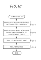
- step S1 in which one of the assortment boxes B1 is moved to the assortment table 13 by the double-arm manipulator 11 will be described with reference to Fig. 10 which illustrates only major operations.
- the double-arm manipulator 11 After the picking system 10 is started up, the double-arm manipulator 11 performs an operation of recognizing the assortment boxes B1 on the conveying carriage 12.
- the double-arm manipulator 11 grips one of the handle bars 61 of the conveying carriage 12 with the support portions 42 of the left hand 35a.
- the double-arm manipulator 11 rotates the top plate 52 so that one of the empty assortment boxes B1 for reception of the bolts can be moved to a predetermined position.
- the double-arm manipulator 11 moves the right hand 35b of the right arm 11b to above one of the assortment boxes B1 placed on the conveying carriage 12 and moves the right hand 35b downwards in that position. If the right hand 35b comes into contact with one of the assortment boxes B1, the output signal of the right force sensor 33b is changed. The position where the change in the output signal occurs can be recognized as the position of the uppermost assortment box B1.
- the size of the assortment boxes B1 and the height of the top plate 52 are known in advance. Therefore, if the position of the uppermost assortment box B1 is known, it is possible to know the number of the assortment boxes B1 stacked in the corresponding row.
- This recognizing operation is repeated with respect to the respective rows.
- the system controller 24 is informed of the total number of the assortment boxes B1 and the subtotal of the assortment boxes B1 in each of the rows on the rotary table 51. In this manner, the positions and number of the assortment boxes B1 can be recognized without having to use a dedicated sensor.
- the double-arm manipulator 11 grips the handles 56 of one of the assortment boxes B1 with the left hand 35a and the right hand 35b and lifts up the assortment box B1 along the guide poles 54 to a position higher than the tip ends of the guide poles 54. Then, the double-arm manipulator 11 swivels the body 11c and moves the assortment box B1 downwards to place the assortment box B1 on the assortment table 13.
- the system controller 24 determines that the assortment box B1 has been normally placed on the assortment table 13. Then, the next step is performed.
- the system controller 24 determines that an abnormality has occurred and performs a predetermined alarming process (e.g., a temporary stop process).
- the double-arm manipulator 11 opens the lid 58 by bringing the gripping claws 36 of the left hand 35a into contact with the lower surface of the knob 59 of the lid 58 and moving the lid 58 upwards.
- the lid 58 is opened at an angle of, e.g., 100 to 140 degrees, from the closed position and is supported by the support member 70.
- the system controller 24 determines that an abnormality has occurred and performs a predetermined alarming process.
- the barcode reader reads the two-dimensional barcode attached to the assortment box B1.
- the information thus read (the first matching information mentioned above) is sent to the system controller 24.
- step S1-5 If the first matching information is not received even when a specified time lapses after the operation of step S1-5, the system controller 24 determines that an abnormality has occurred and performs a predetermined alarming process.
- step S2 in which the double-arm manipulator 11 transfers the bolts contained in the workpiece racks 20 to the assortment box B1 placed on the assortment table 13 will be described with reference to Fig. 11 which illustrates only major operations.
- the system controller 24 grasps the information on the kind and number of the bolts to be put into the respective compartments of the assortment box B1 on the assortment table 13.
- the system controller 24 sends to the robot controller 22 a command "Go to take the workpiece box B2 containing the bolts of the desired kind". Responsive to this command, the robot controller 22 controls the double-arm manipulator 11. Pursuant to a command received from the robot controller 22, the double-arm manipulator 11 swivels the body 11c and takes the workpiece box B2 stored in a predetermined compartment of the workpiece racks 20. More specifically, the double-arm manipulator 11 grips the rear plate 120c of the workpiece box B2 with the gripping claws 44 of the right hand 35b in the vertical direction and takes out the workpiece box B2 toward itself.
- the weight of the bolts contained in the workpiece box B2 is measured by the right force sensor 33b.
- the weight of the workpiece box B2 initially gripped by the double-arm manipulator 11 after the startup of the workpiece picking system 10 is stored in the system controller 24 as an initial weight.
- the double-arm manipulator 11 swivels the body 11c to directly face the work table 17. Then, the double-arm manipulator 11 takes down the front end of the gripped workpiece box B2, above the tiltable plate 80 of the work table 17, and holds the workpiece box B2 in a tilted state.
- the double-arm manipulator 11 grips the raking tool 15 on the stand 75 with the tool holding members 41 of the left hand 35a.
- Fig. 7 schematically shows a situation in which the bolts are raked out by the double-arm manipulator 11.
- the left hand 35a for gripping the raking tool 15 and the right hand 35b for gripping the workpiece box B2 are omitted in Fig. 7 .
- the raking tool 15 is brought into the workpiece box B2 while monitoring the output value of the left force sensor 33a.
- the position in which the output value of the left force sensor 33a shows a change i.e., the position in which the raking tool 15 makes contact with the bolts, is assumed to be a reference height h0 from the bottom surface of the workpiece box B2 (see Fig. 8A ).
- the double-arm manipulator 11 brings the raking tool 15 downwards from the reference height h0 by a predetermined depth (e.g., 0.5 to 5 mm) and moves the raking tool 15 forwards, thereby raking out the bolts from the workpiece box B2.
- the raking force is adjusted depending on the measured value of the left force sensor 33a provided in the left arm 11a.
- the bolts on the tiltable plate 80 are imaged by the two-dimensional camera 100 and subjected to image processing. If the bolts overlap with one another, it becomes difficult or impossible to detect the position and posture of the bolts in a two-dimensional image. Accordingly, it is desirable that the raked-out bolts be dispersed on the tiltable plate 80 so as not to overlap with one another.
- the number of bolts required in optimally detecting the position and posture of the bolts from the two-dimensional image is empirically found and set in advance. The pre-set number of bolts are raked out depending on the output value of the left force sensor 33a. This reduces the possibility that the bolts overlap with one another on the tiltable plate 80, consequently increasing the number of bolts of which the position and posture are detected from the two-dimensional image.
- the double-arm manipulator 11 can serve as a workpiece supply unit for raking out the bolts from the workpiece box B2 and supplying the bolts to the work table 17.
- step S2-9 is carried out if it is determined that a predetermined number of bolts have been raked out.
- the predetermined number of bolts is found pursuant to the output value of the right force sensor 33b. This makes it possible to measure the predetermined number of bolts with no provision of a dedicated sensor, e.g., a weight scale.
- a second raking operation is performed.
- the raking tool 15 is moved downwards deeper than in the first raking operation (e.g., by a depth of 3 to 10 mm) to rake out the bolts at a height h1 (see Fig. 8B ).
- step S2-9 is carried out if it is determined that the predetermined number of bolts have been raked out.
- a third raking operation is performed.
- the raking tool 15 is moved downwards deeper than in the second raking operation (e.g., by a depth of 5 to 15 mm) to rake out the bolts.
- step S2-9 is carried out if it is determined that the predetermined number of bolts have been raked out.
- a fourth raking operation is performed.
- the raking tool 15 is moved downwards deeper than in the third raking operation (e.g., by a depth of 7 to 20 mm) to rake out the bolts.
- step S2-9 is carried out regardless of whether the predetermined number of bolts have been raked out. While the raking operations are performed four times at most in the present embodiment, the number of raking operations may be set arbitrarily.
- the double-arm manipulator 11 returns the raking tool 15 gripped by the left hand 35a to the stand 75.
- the bolts of the same kind raked out onto the tiltable plate 80 are imaged by the two-dimensional camera 100 under the control of the system controller 24.
- the two-dimensional image of the bolts undergoes, e.g., an edge detecting process, in the image processing computer 26.
- the position and posture of the bolts dispersed on the tiltable plate 80 is found by comparing the detected edges with the templates of bolts stored in advance.
- the image processing computer 26 recognize workpiece those that have a high degree of correlation than the threshold as qualified workpiece.
- the robot controller 22 receives the position and posture of the bolts from the system controller 24.
- the robot controller 22 Based on the position and posture of the bolts, the robot controller 22 operates the double-arm manipulator 11 (the gripping claws 36 of the left hand 35a).
- the double-arm manipulator 11 causes the gripping claws 36 of the left hand 35a to rotate about the picking axis AXp to an orientation in which the gripping claws 36 can grip the bolts with ease.
- the gripping claws 36 grip one of the bolts on the tiltable plate 80.
- the double-arm manipulator 11 transfers the gripped bolt to a predetermined compartment within the assortment box B1 (the compartment matched by the first matching information).
- This step is repeated as many times as the number of bolts contained in the first matching information so that a predetermined number of bolts of the same kind can be put into the predetermined compartment.
- the workpiece box B2 gripped by the right hand 35b is temporarily arranged on the workpiece box stand 90 of the work table 17.
- the double-arm manipulator 11 is stopped for a while.
- the transfer operation stop condition includes 1 bolts as many as indicated by the two-dimensional barcode having been put into the assortment box B1 or 2 the bolts on the tilting top plate 80 becoming shortage in the midst of the transfer operation.
- the double-arm manipulator 11 grips the tiltable plate 80 with the support portions 42 of the left hand 35a and tilts the tiltable plate 80 about the rotation axis AX4. This returns the bolts on the tiltable plate 80 into the workpiece box B2 placed on the workpiece box stand 90. At this time, the double-arm manipulator 11 presses the workpiece box B2 with the right hand 35b to hold the workpiece box B2 against movement. Since the double-arm manipulator 11 returns the bolts into the workpiece box B2 by tilting the tiltable plate 80, there is no need to provide a dedicated mechanism for returning the bolts to the workpiece box B2.
- step S2-14 is carried out.
- the flow comes back to step S2-4 to repeat the raking operation until the number of bolts put into the assortment box B1 reaches the number of bolts contained in the first matching information.
- the double-arm manipulator 11 grips the workpiece box B2 with the right hand 35b and returns the workpiece box B2 to the original workpiece rack 20.
- the system controller 24 measures the weight of the bolts remaining in the workpiece box B2 pursuant to the output signal of the right force sensor 33b. Accordingly, it is possible to measure the weight of the bolts remaining in the workpiece box B2 with no provision of a dedicated sensor, e.g., a weight scale.
- the system controller 24 turns on the relevant lamp of the workpiece racks 20. For example, the system controller 24 turns on the relevant lamp if the weight of the bolts remaining in the workpiece box B2 is equal to or less than 80% of the initial weight stored in step S2-2. This enables the worker to confirm the timing at which the bolts are to be supplemented into the workpiece box B2.
- the system controller 24 determines whether all kinds of bolts have been transferred to the respective compartments of the assortment box B1. If yes in step S2-15, step S3 is carried out. If no in step S2-15, the double-arm manipulator 11 repeats steps S2-2 through S2-14 to transfer different kinds of bolts to the assortment box B1.
- step S3 in which the assortment box B1 holding the bolts is returned by the double-arm manipulator 11 will be described with reference to Fig. 12 .
- the double-arm manipulator 11 causes the gripping claws 36 of the left hand 35a to face downwards.
- the double-arm manipulator 11 closes the lid 58 by bringing the gripping claws 36 into contact with the knob 59 of the lid 58 supported on the support member 70 and moving the knob 59 toward itself.
- the double-arm manipulator 11 grips one of the handle bars 61 of the conveying carriage 12 with the support portions 42 of the left hand 35a and rotates the top plate 52 of the rotary table 51 into a predetermined position.
- the double-arm manipulator 11 grips the handles 56 of the assortment box B1 with the left hand 35a and the right hand 35b and rotates the body 11c toward the conveying carriage 12 while lifting up the assortment box B1.
- the double-arm manipulator 11 lowers the assortment box B1 along the guide poles 54 and arranges the assortment box B1 on the top plate 52 of the rotary table 51. At this time, if one assortment box B1 holding bolts is already placed in the empty space of the conveying carriage 12, other assortment boxes B1 holding bolts are stacked thereon up to a specified height.
- the picking system 10 repeats steps S1-2 through S3-2 with respect to all the assortment boxes B1 loaded on the conveying carriage 12 (see Fig. 9 ).
- the picking system 10 can take out a predetermined number of specific bolts from the workpiece racks 20 using the two-dimensional camera 100 and the double-arm manipulator 11 and can put the bolts into the assortment boxes B1 loaded on the conveying carriage 12.
- the operations mentioned above may not be performed one after another but may be performed in parallel if possible.
- the conveying carriage 12 loaded with the assortment boxes B1 holding bolts is carried out through the gateway.
- the assortment boxes B1 may be conveyed by a conveyor in place of the conveying carriage 12.
- the information storage medium is not limited to the two-dimensional barcode but may be, e.g., an IC tag. In this case, an IC tag reader is used in place of the barcode reader.
- the workpiece s are not limited to the bolts.
- the workpiece s may be other kinds of workpiece (parts or product), e.g., electronic parts.
- the left arm 11a or the right arm 11b is not limited to the multi-joint manipulator having seven axes but may be a multi-joint manipulator having more than seven axes.
- the double-arm manipulator 11 serves also as a workpiece supply unit.
- a workpiece supply unit for supplying parts onto a work table may be provided independently of a manipulator for transferring parts.
Landscapes
- Engineering & Computer Science (AREA)
- Robotics (AREA)
- Mechanical Engineering (AREA)
- Physics & Mathematics (AREA)
- General Physics & Mathematics (AREA)
- Human Computer Interaction (AREA)
- Computer Vision & Pattern Recognition (AREA)
- Theoretical Computer Science (AREA)
- Geometry (AREA)
- Manufacturing & Machinery (AREA)
- Automation & Control Theory (AREA)
- Manipulator (AREA)
- Warehouses Or Storage Devices (AREA)
Applications Claiming Priority (1)
| Application Number | Priority Date | Filing Date | Title |
|---|---|---|---|
| JP2010194559A JP5489000B2 (ja) | 2010-08-31 | 2010-08-31 | 作業装置及び部品ピッキングシステム |
Publications (2)
| Publication Number | Publication Date |
|---|---|
| EP2422937A2 true EP2422937A2 (de) | 2012-02-29 |
| EP2422937A3 EP2422937A3 (de) | 2014-05-07 |
Family
ID=44582497
Family Applications (1)
| Application Number | Title | Priority Date | Filing Date |
|---|---|---|---|
| EP11179416.0A Withdrawn EP2422937A3 (de) | 2010-08-31 | 2011-08-30 | Robotersystem |
Country Status (5)
| Country | Link |
|---|---|
| US (1) | US8954182B2 (de) |
| EP (1) | EP2422937A3 (de) |
| JP (1) | JP5489000B2 (de) |
| KR (1) | KR20120022075A (de) |
| CN (1) | CN102430530B (de) |
Cited By (4)
| Publication number | Priority date | Publication date | Assignee | Title |
|---|---|---|---|---|
| EP2489482A3 (de) * | 2011-02-18 | 2014-11-19 | Kabushiki Kaisha Yaskawa Denki | Arbeitsauswahlsystem |
| CN103659811B (zh) * | 2012-09-13 | 2015-09-30 | 发那科株式会社 | 根据选择条件决定机器人的保持位置姿态的物品取出装置 |
| CN106426189A (zh) * | 2016-07-13 | 2017-02-22 | 福建工程学院 | 打磨抛光机器人工件夹持的自动纠偏方法 |
| CN109015642A (zh) * | 2018-08-16 | 2018-12-18 | 苏州市运泰利自动化设备有限公司 | 上下料控制方法及系统 |
Families Citing this family (28)
| Publication number | Priority date | Publication date | Assignee | Title |
|---|---|---|---|---|
| JP5549716B2 (ja) * | 2012-08-31 | 2014-07-16 | 株式会社安川電機 | ロボットシステムおよび教示方法 |
| CN103325106B (zh) * | 2013-04-15 | 2015-11-25 | 浙江工业大学 | 基于LabVIEW的运动工件分拣方法 |
| JP2014226739A (ja) * | 2013-05-20 | 2014-12-08 | 三菱電機株式会社 | 部品払出装置および部品払出方法 |
| CN103817396A (zh) * | 2013-11-19 | 2014-05-28 | 芜湖普威技研有限公司 | 一种机器人焊接生产线及其使用方法 |
| CN103691681A (zh) * | 2013-12-29 | 2014-04-02 | 卓朝旦 | 透明药丸自动分拣装置 |
| JP6068429B2 (ja) * | 2014-12-25 | 2017-01-25 | ファナック株式会社 | ロボット識別システム |
| KR102018742B1 (ko) * | 2015-07-30 | 2019-09-05 | 카와사키 주코교 카부시키 카이샤 | 로봇 및 그 제어 방법 |
| EP4235539A3 (de) | 2015-09-11 | 2023-09-27 | Berkshire Grey Operating Company, Inc. | Robotersysteme und verfahren zur identifikation und verarbeitung von verschiedenen objekten |
| EP3383593B1 (de) * | 2015-12-03 | 2021-04-28 | ABB Schweiz AG | Anlernen eines industrieroboters zum greifen von teilen |
| US12350713B2 (en) | 2015-12-18 | 2025-07-08 | Berkshire Grey Operating Company, Inc. | Perception systems and methods for identifying and processing a variety of objects |
| US9937532B2 (en) | 2015-12-18 | 2018-04-10 | Berkshire Grey Inc. | Perception systems and methods for identifying and processing a variety of objects |
| CN105728331B (zh) * | 2016-03-23 | 2018-02-06 | 山东道先为智能科技有限公司 | 全自动驭料分拣系统及驭料分拣方法 |
| CN106040616B (zh) * | 2016-08-12 | 2018-02-06 | 乐山新天源太阳能科技有限公司 | 全自动电池片功率分选机 |
| CN106269582B (zh) * | 2016-08-12 | 2018-03-20 | 乐山新天源太阳能科技有限公司 | 用于电池片功率分选机的放片装置 |
| CN106269534B (zh) * | 2016-08-12 | 2018-04-13 | 乐山新天源太阳能科技有限公司 | 用于电池片功率分选机的分选装置 |
| CN106216270B (zh) * | 2016-08-12 | 2018-03-20 | 乐山新天源太阳能科技有限公司 | 全自动电池片功率分选机 |
| JP6444563B2 (ja) * | 2016-10-13 | 2018-12-26 | 三菱電機株式会社 | 生産支援システム、表示器、生産支援方法、生産支援プログラムおよび記録媒体 |
| CN106426186B (zh) * | 2016-12-14 | 2019-02-12 | 国网江苏省电力公司常州供电公司 | 一种基于多传感器信息融合的带电作业机器人自主作业方法 |
| EP3395451A1 (de) * | 2017-04-24 | 2018-10-31 | Siemens Aktiengesellschaft | Übertragungsvorrichtung und verfahren zur übertragung von stückgütern |
| JP7057214B2 (ja) * | 2018-05-18 | 2022-04-19 | トヨタ自動車株式会社 | 把持装置、タグが付された容器、対象物把持プログラムおよび対象物把持方法 |
| JP2020168679A (ja) * | 2019-04-03 | 2020-10-15 | セイコーエプソン株式会社 | ロボットシステム及び撮像方法 |
| JP7291946B2 (ja) * | 2019-09-04 | 2023-06-16 | 株式会社ニチリン | 粉粒体の自動計量装置 |
| JP7376319B2 (ja) * | 2019-10-31 | 2023-11-08 | 矢崎総業株式会社 | ワークピッキング装置 |
| CN112849866B (zh) * | 2019-11-27 | 2024-06-25 | 株式会社大福 | 物品输送装置 |
| US11130237B1 (en) | 2020-03-05 | 2021-09-28 | Mujin, Inc. | Method and computing system for performing container detection and object detection |
| JP6796901B1 (ja) * | 2020-03-05 | 2020-12-09 | 株式会社Mujin | 容器検出および物体検出を行うための方法ならびに計算システム |
| US12134525B2 (en) | 2021-05-12 | 2024-11-05 | Berkshire Grey Operating Company, Inc. | Systems and methods for assisting in object grasping from containers in object processing systems |
| USD1104094S1 (en) * | 2024-02-07 | 2025-12-02 | Hyosung TNS Inc. | Robot cafe booth |
Citations (1)
| Publication number | Priority date | Publication date | Assignee | Title |
|---|---|---|---|---|
| JP2555822B2 (ja) | 1991-10-30 | 1996-11-20 | 日本電装株式会社 | 山積み部品の高速ピッキング装置 |
Family Cites Families (12)
| Publication number | Priority date | Publication date | Assignee | Title |
|---|---|---|---|---|
| US4187051A (en) * | 1978-05-26 | 1980-02-05 | Jerry Kirsch | Rotary video article centering, orienting and transfer device for computerized electronic operating systems |
| US4305130A (en) * | 1979-05-29 | 1981-12-08 | University Of Rhode Island | Apparatus and method to enable a robot with vision to acquire, orient and transport workpieces |
| DE3204180A1 (de) * | 1982-02-06 | 1983-08-11 | Hartmann & Lämmle GmbH & Co KG, 7255 Rutesheim | "industrieroboter" |
| US4640655A (en) * | 1985-04-12 | 1987-02-03 | Con-Vey/Keystone, Inc. | Continuous feeding apparatus |
| US5211528A (en) * | 1989-08-31 | 1993-05-18 | Mitsubishi Denki Kabushiki Kaisha | Industrial robot apparatus |
| GB2261069B (en) | 1991-10-30 | 1995-11-01 | Nippon Denso Co | High speed picking system for stacked parts |
| US5419457A (en) * | 1993-08-30 | 1995-05-30 | Electrocom Gard Ltd. | System for sorting mail pieces on multiple levels and a method for performing the same |
| JPH09108957A (ja) * | 1995-10-20 | 1997-04-28 | Fuji Photo Film Co Ltd | 部品供給装置 |
| JP3300682B2 (ja) * | 1999-04-08 | 2002-07-08 | ファナック株式会社 | 画像処理機能を持つロボット装置 |
| JP3865703B2 (ja) | 2002-10-25 | 2007-01-10 | ファナック株式会社 | 物品搬送システム及び搬送方法 |
| CN2858078Y (zh) * | 2005-08-03 | 2007-01-17 | 湖南大学 | 多视觉空瓶检测机器人 |
| DE102006034455A1 (de) * | 2006-07-26 | 2008-01-31 | Carl Zeiss Industrielle Messtechnik Gmbh | Lageveränderliche Werkstückauflage für eine Maschine und Bearbeitungsanlage mit einer entsprechenden Werkstückauflage |
-
2010
- 2010-08-31 JP JP2010194559A patent/JP5489000B2/ja active Active
-
2011
- 2011-08-30 EP EP11179416.0A patent/EP2422937A3/de not_active Withdrawn
- 2011-08-30 US US13/221,013 patent/US8954182B2/en not_active Expired - Fee Related
- 2011-08-31 KR KR1020110088173A patent/KR20120022075A/ko not_active Ceased
- 2011-08-31 CN CN201110255889.4A patent/CN102430530B/zh not_active Expired - Fee Related
Patent Citations (1)
| Publication number | Priority date | Publication date | Assignee | Title |
|---|---|---|---|---|
| JP2555822B2 (ja) | 1991-10-30 | 1996-11-20 | 日本電装株式会社 | 山積み部品の高速ピッキング装置 |
Cited By (7)
| Publication number | Priority date | Publication date | Assignee | Title |
|---|---|---|---|---|
| EP2489482A3 (de) * | 2011-02-18 | 2014-11-19 | Kabushiki Kaisha Yaskawa Denki | Arbeitsauswahlsystem |
| US8948904B2 (en) | 2011-02-18 | 2015-02-03 | Kabushiki Kaisha Yaskawa Denki | Work picking system |
| CN103659811B (zh) * | 2012-09-13 | 2015-09-30 | 发那科株式会社 | 根据选择条件决定机器人的保持位置姿态的物品取出装置 |
| CN106426189A (zh) * | 2016-07-13 | 2017-02-22 | 福建工程学院 | 打磨抛光机器人工件夹持的自动纠偏方法 |
| WO2018010373A1 (zh) * | 2016-07-13 | 2018-01-18 | 福建工程学院 | 打磨抛光机器人工件夹持的自动纠偏方法 |
| CN106426189B (zh) * | 2016-07-13 | 2019-09-20 | 福建工程学院 | 打磨抛光机器人工件夹持的自动纠偏方法 |
| CN109015642A (zh) * | 2018-08-16 | 2018-12-18 | 苏州市运泰利自动化设备有限公司 | 上下料控制方法及系统 |
Also Published As
| Publication number | Publication date |
|---|---|
| JP2012051056A (ja) | 2012-03-15 |
| US8954182B2 (en) | 2015-02-10 |
| CN102430530B (zh) | 2014-11-05 |
| EP2422937A3 (de) | 2014-05-07 |
| JP5489000B2 (ja) | 2014-05-14 |
| CN102430530A (zh) | 2012-05-02 |
| KR20120022075A (ko) | 2012-03-09 |
| US20120053724A1 (en) | 2012-03-01 |
Similar Documents
| Publication | Publication Date | Title |
|---|---|---|
| EP2422937A2 (de) | Robotersystem | |
| CN112215557B (zh) | 仓储管理系统及方法 | |
| US8616599B2 (en) | Hand and robot | |
| JP5429117B2 (ja) | ハンド及びロボット | |
| EP3434380A2 (de) | Sortiervorrichtung und sortiersystem | |
| CN113165129A (zh) | 齐套拣货机 | |
| JP7171231B2 (ja) | 搬送用装置、検体測定システムおよび搬送方法 | |
| JP2018176313A (ja) | 物品移載装置 | |
| JP2006035397A (ja) | 搬送ロボットシステム | |
| US20200376668A1 (en) | Robotic Pack Station | |
| EP3620409B1 (de) | Chargenbasierter kommissionierroboter | |
| JP2010520076A (ja) | 対象物を認識、回収および再配置する方法および装置 | |
| JP7057155B2 (ja) | 容器供給装置 | |
| CN102672724A (zh) | 自动作业装置 | |
| CN118742417A (zh) | 机器人以及具备该机器人的细长部件的拾取系统 | |
| JP4007204B2 (ja) | ロボットシステム | |
| JP5617512B2 (ja) | ハンド及びロボット | |
| JP6643921B2 (ja) | 仕分装置および物品取出方法 | |
| EP4149869B1 (de) | Verfahren zum entleeren einer schachtel | |
| JP2023100452A (ja) | 食器洗浄補助装置および食器洗浄システム | |
| GB2485416A (en) | Garment handling apparatus and method | |
| JP4152057B2 (ja) | 農産物の搬送装置 | |
| JP3849633B2 (ja) | 物品群の積み付け組み様式の認識方法および装置ならびに認識装置を具備した物品移載設備 | |
| JP2023100453A (ja) | 食器洗浄補助装置および食器洗浄システム | |
| EP2380828A1 (de) | Vorrichtung zur Lagerung von in der Nähe eines Zufuhrelements sukzessive zu empfangenden Objekten |
Legal Events
| Date | Code | Title | Description |
|---|---|---|---|
| AK | Designated contracting states |
Kind code of ref document: A2 Designated state(s): AL AT BE BG CH CY CZ DE DK EE ES FI FR GB GR HR HU IE IS IT LI LT LU LV MC MK MT NL NO PL PT RO RS SE SI SK SM TR |
|
| AX | Request for extension of the european patent |
Extension state: BA ME |
|
| PUAI | Public reference made under article 153(3) epc to a published international application that has entered the european phase |
Free format text: ORIGINAL CODE: 0009012 |
|
| PUAL | Search report despatched |
Free format text: ORIGINAL CODE: 0009013 |
|
| AK | Designated contracting states |
Kind code of ref document: A3 Designated state(s): AL AT BE BG CH CY CZ DE DK EE ES FI FR GB GR HR HU IE IS IT LI LT LU LV MC MK MT NL NO PL PT RO RS SE SI SK SM TR |
|
| AX | Request for extension of the european patent |
Extension state: BA ME |
|
| RIC1 | Information provided on ipc code assigned before grant |
Ipc: B25J 9/16 20060101AFI20140328BHEP |
|
| 17P | Request for examination filed |
Effective date: 20141021 |
|
| RBV | Designated contracting states (corrected) |
Designated state(s): AL AT BE BG CH CY CZ DE DK EE ES FI FR GB GR HR HU IE IS IT LI LT LU LV MC MK MT NL NO PL PT RO RS SE SI SK SM TR |
|
| STAA | Information on the status of an ep patent application or granted ep patent |
Free format text: STATUS: THE APPLICATION HAS BEEN WITHDRAWN |
|
| 18W | Application withdrawn |
Effective date: 20160728 |