EP2423112A1 - Dispositif et procédé de fabrication d'emballages pour cigarettes - Google Patents
Dispositif et procédé de fabrication d'emballages pour cigarettes Download PDFInfo
- Publication number
- EP2423112A1 EP2423112A1 EP11005128A EP11005128A EP2423112A1 EP 2423112 A1 EP2423112 A1 EP 2423112A1 EP 11005128 A EP11005128 A EP 11005128A EP 11005128 A EP11005128 A EP 11005128A EP 2423112 A1 EP2423112 A1 EP 2423112A1
- Authority
- EP
- European Patent Office
- Prior art keywords
- glue
- units
- cleaning
- folding
- transport path
- Prior art date
- Legal status (The legal status is an assumption and is not a legal conclusion. Google has not performed a legal analysis and makes no representation as to the accuracy of the status listed.)
- Granted
Links
- 235000019504 cigarettes Nutrition 0.000 title claims abstract description 19
- 238000004806 packaging method and process Methods 0.000 title claims description 5
- 238000004519 manufacturing process Methods 0.000 title claims description 3
- 238000000034 method Methods 0.000 title description 5
- 239000003292 glue Substances 0.000 claims abstract description 238
- 238000004140 cleaning Methods 0.000 claims abstract description 79
- 239000005022 packaging material Substances 0.000 claims abstract description 4
- 239000004831 Hot glue Substances 0.000 claims description 34
- 210000000056 organ Anatomy 0.000 claims description 18
- 239000012459 cleaning agent Substances 0.000 claims description 5
- 238000009413 insulation Methods 0.000 claims description 5
- 238000009826 distribution Methods 0.000 claims description 4
- 238000009429 electrical wiring Methods 0.000 claims description 2
- 230000003750 conditioning effect Effects 0.000 claims 1
- 238000012856 packing Methods 0.000 abstract 1
- 239000012943 hotmelt Substances 0.000 description 3
- 239000003795 chemical substances by application Substances 0.000 description 2
- 238000004026 adhesive bonding Methods 0.000 description 1
- 238000011109 contamination Methods 0.000 description 1
- 238000001816 cooling Methods 0.000 description 1
- 230000001419 dependent effect Effects 0.000 description 1
- 239000003599 detergent Substances 0.000 description 1
- 239000006260 foam Substances 0.000 description 1
- 238000010438 heat treatment Methods 0.000 description 1
- 230000001681 protective effect Effects 0.000 description 1
- 238000004513 sizing Methods 0.000 description 1
- 238000011144 upstream manufacturing Methods 0.000 description 1
- XLYOFNOQVPJJNP-UHFFFAOYSA-N water Substances O XLYOFNOQVPJJNP-UHFFFAOYSA-N 0.000 description 1
Images



Classifications
-
- B—PERFORMING OPERATIONS; TRANSPORTING
- B65—CONVEYING; PACKING; STORING; HANDLING THIN OR FILAMENTARY MATERIAL
- B65B—MACHINES, APPARATUS OR DEVICES FOR, OR METHODS OF, PACKAGING ARTICLES OR MATERIALS; UNPACKING
- B65B19/00—Packaging rod-shaped or tubular articles susceptible to damage by abrasion or pressure, e.g. cigarettes, cigars, macaroni, spaghetti, drinking straws or welding electrodes
- B65B19/02—Packaging cigarettes
- B65B19/22—Wrapping the cigarettes; Packaging the cigarettes in containers formed by folding wrapping material around formers
- B65B19/223—Wrapping the cigarettes; Packaging the cigarettes in containers formed by folding wrapping material around formers in a curved path; in a combination of straight and curved paths, e.g. on rotary tables or other endless conveyors
-
- B—PERFORMING OPERATIONS; TRANSPORTING
- B05—SPRAYING OR ATOMISING IN GENERAL; APPLYING FLUENT MATERIALS TO SURFACES, IN GENERAL
- B05B—SPRAYING APPARATUS; ATOMISING APPARATUS; NOZZLES
- B05B15/00—Details of spraying plant or spraying apparatus not otherwise provided for; Accessories
- B05B15/50—Arrangements for cleaning; Arrangements for preventing deposits, drying-out or blockage; Arrangements for detecting improper discharge caused by the presence of foreign matter
- B05B15/52—Arrangements for cleaning; Arrangements for preventing deposits, drying-out or blockage; Arrangements for detecting improper discharge caused by the presence of foreign matter for removal of clogging particles
-
- B—PERFORMING OPERATIONS; TRANSPORTING
- B65—CONVEYING; PACKING; STORING; HANDLING THIN OR FILAMENTARY MATERIAL
- B65B—MACHINES, APPARATUS OR DEVICES FOR, OR METHODS OF, PACKAGING ARTICLES OR MATERIALS; UNPACKING
- B65B51/00—Devices for, or methods of, sealing or securing package folds or closures; Devices for gathering or twisting wrappers, or necks of bags
- B65B51/02—Applying adhesives or sealing liquids
- B65B51/023—Applying adhesives or sealing liquids using applicator nozzles
Definitions
- the invention relates to a device for producing packages for cigarettes, in particular of the folding box type, with a folding device, in particular a folding turret, for folding blanks of packaging material, in particular thin cardboard, and with a subsequent to the folding conveyor transport path, in particular packaging web, for a large extent finished packs, wherein in the transport path a glue application station with glue units, in particular glue nozzles, is provided for applying glue to folding flaps of the blank, according to the preamble of claim 1. Furthermore, the invention relates to a corresponding method according to the preamble of claim 15.
- the invention is based on the object of further developing devices and methods of the type mentioned, in particular with regard to the simultaneous application of cold glue and hot glue on folding flaps of a cigarette pack.
- a device has the features of claim 1. It is therefore provided that the glue units are arranged in a glue application position on both sides of the transport path at the level of the folding flaps to be glued and are movable together in at least one cleaning position for cleaning the glue units.
- the cleaning of the glue units prevents the problems mentioned above and leads to a proper glue pattern.
- a first cleaning position Leimportionen against a arranged between the glue aggregates common collecting organ can be issued. Furthermore, it can additionally be provided that in a second cleaning position, in particular the glue units for applying cold glue can be cleaned by abutment against a common cleaning member.
- glue units are arranged in the or each cleaning position in a plane below the preferably horizontally oriented transport path.
- Another special feature may be that on the one hand glue units for applying cold glue and on the other hand glue units for applying hot glue are arranged successively along the transport path, the respective glue units are arranged opposite each other on both sides of the transport path for applying corresponding glue on preferably upright folding tabs in the range of Narrow sides of the package and that the glue units for applying cold glue on the one hand and the glue units for applying hot glue on the other hand are each movable together in at least one cleaning position.
- the glue units for applying cold glue on the one hand and the glue units for applying hot glue on the other hand can be moved independently by separate drives between the glue application position and the or each cleaning position.
- the glue units for applying cold glue on the one hand and the glue units for applying hot glue on the other hand are preferably movable in a substantially vertical direction.
- Another special feature may consist in that in each case a collecting device for hot glue and cold glue is provided, wherein the collecting organs each extend upright between the opposite glue units, which are preferably arranged for dispensing glue portions in a substantially horizontal direction, preferably below the respective Collecting member is provided in each case a collecting means, in particular a glue trough, for given by the respective collecting organ glue, wherein the collecting means are separately handled and in particular emptied.
- the collecting device for hot glue is heated to avoid glue deposits and to forward the glue to an associated collecting means.
- Another special feature may consist in that the glue units for applying cold glue in the second cleaning position abut against stationary rotatable cleaning rollers, wherein the cleaning rollers are driven by a common drive and each rest on another pair of lower cleaning rollers, which are wettable with a detergent , in particular by immersing the lower one Cleaning rollers in a container the cleaning agent, wherein the container is mounted laterally removable together with the lower cleaning rollers for cleaning purposes.
- the glue units, the collecting organs and the collecting means are connected to a jointly movable unit, which is mounted without retracting the relative position of said organs together from the device.
- the jointly movable unit may have an electrical wiring box movable together with the unit, such that the members of the unit are connected to the junction box.
- a device for aligning side tabs in the region of a lid of the pack is arranged, in particular an aligner shaft, wherein the glue units in Connected to the device are arranged such that the folding flaps of the blank can be glued immediately after the alignment of the lid of the pack.
- a method according to the invention has the features of claim 15. It is therefore envisaged that the glue units are moved together from a glue application position on both sides of the transport path at the level of the folding flaps to be glued into at least one cleaning position for cleaning the glue units.
- This type of package consists of box part 11 and lid 12.
- the box part 11 has a box front wall 13 and a box rear wall 14, which are connected to each other via a bottom wall 15.
- the lid 12 includes a lid front wall 16, a lid rear wall 17, and a lid end wall 18 therebetween.
- the schematic in Fig. 4 illustrated device as part of a packaging machine for producing cigarette packs of the type folding box consists of a folding turret 23, a subsequent (straight) transport path 24 and a transfer turret 25th
- Contents of the pack 10 is a cigarette block 26 in the form of a cigarette group wrapped in an inner blank.
- the cigarette block 26 is enveloped in the area of the folding turret 23 in a blank for the pack 10.
- the largely finished pack 10 is ejected in the radial direction from pockets of the folding turret 23 and transferred to the transport path 24.
- the packs 10 are transported at a distance from each other by an endless conveyor.
- This is designed as a belt conveyor 27, as a toothed belt.
- On the free side drivers 28 are arranged, each detecting and transporting a pack 10 in the region of the rear bottom wall 15.
- the packs 10 lie with their longitudinal extent pointing in the conveying direction on the belt conveyor 27 and / or on a longitudinal direction of the transport path 24 extending guide profile 29.
- guide and support members are provided in the region of the transport path.
- the laterally directed folding tabs namely box side tabs 19 and lid side tabs 21, rest on legs 30 of the guide profile 29.
- guide rails 31 extending in the conveying direction are arranged on the upper side of the packs 10 and hold the packs 10 in the exact position on or in the conveying track 24.
- the packages 10 are preferably transported continuously along the transport path 24.
- folding flaps are provided with glue, in the present case, the upright inner box side flaps 20 and lid side flaps 22.
- the package 10 is ready folded, namely by folding the box side flaps 19 and lid side tabs 21 until it rests against the associated side tabs 20, 22.
- the now finished package 10 is transferred to the forming unit, namely to the transfer turret 25th
- the device is adapted to transfer two different types of glue to the package 10, namely cold glue on the one hand and hot melt (hotmelt) on the other.
- a first glue station 32 is used to transfer hot glue.
- a second sizing station 33 following in the conveying direction is set up for the transfer of cold glue.
- the first glue station 32 has two glue units 34, 35 on both sides of the transport path 24.
- the glue units 34, 35 have glue nozzles 36 for transferring glue dots 37 onto the package 10.
- a special feature is that the glue portions are dispensed in a horizontal direction and transferred to an upright folding flap 20, 22.
- the second glue station 33 in the present case also consists of two glue units 40, 41 on both sides of the transport path 24 for the transfer of individual glue spots 42 of another type of glue, namely cold glue.
- the glue units 40, 4 of the second glue station 33 are designed or arranged such that two superimposed rows of dots 38, 39 of the glue are produced. As compared to the FIGS. 2 and 3 it can be seen that in packs 10 with a smaller number of layers of cigarettes in the cigarette block 26, only one row of dots 38 is attached by appropriate control of the glue units 40, 41.
- the glue points 42 of the first glue station 32 are mounted in a lower plane relative to the transport path 24.
- the glue spots 42 of hotmelt are applied between glue points 37 of the point row 38, ie adjacent to a free edge for connection to the side flaps 20, 22 certain outer side lobes 19,21.
- the glue points 37, 42 can during the stoppage of the packs 10 by the appropriately trained glue units 34, 35; 40, 41 are transmitted. in the In the present case, the glue spots 37, 42, however, by the glue units 34, 35; 40, 41 transferred during the movement of the packs 10 on the side lobes 20, 22.
- the packs 10 reach the region of a folding station with folding members, which in the present case are designed as folding switches 43 on both sides of the conveying track 24.
- folding members which in the present case are designed as folding switches 43 on both sides of the conveying track 24.
- the shaped, rail-like Faltrise 43 cause the side tabs 19, 21 are folded down during transport to the complete abutment against the side flaps 20, 22.
- the finished package 10 is conveyed away.
- a special feature of the device is that the glue units 34, 35 on the one hand and glue units 40, 41 on the other hand can each be moved in pairs in one or more cleaning positions.
- the glue units 34, 35 of the glue station 32 for the application of hot glue can be moved in the vertical direction, or substantially transversely to the transport path 24, namely in a cleaning position below the transport path 24.
- This cleaning position is in Fig. 7 shown.
- Fig. 6 a glue application position of the glue station 32.
- dashed lines is in Fig. 6 the cleaning position according to Fig. 7 indicated.
- the glue units 34, 35 are mounted in the present case on a common, not shown in detail, support means 44, which is movable in the present case by means of a pneumatic cylinder 45 as a drive in the vertical direction.
- support means 44 which is movable in the present case by means of a pneumatic cylinder 45 as a drive in the vertical direction.
- pneumatic cylinder 45 As a drive in the vertical direction.
- other drives come into question for this purpose.
- the two glue units 34, 35 are supplied via hot glue lines 46 with hot glue.
- both the hot glue lines 46 are insulated or heated and the hot glue connections 47 of the hot glue lines 46 on the glue units 34, 35.
- a stationary collecting element 49 is arranged between the glue units 34, 35 and the nozzle tips 48.
- the collecting member 49 serves to receive glue portions of hot glue, which are delivered in the cleaning position of the two glue units 34, 35 in order to prevent clogging of the glue units 34, 35.
- the collecting element 49 is arranged at a distance from the mutual nozzle tips 49 and prevents the mutual glue units 34, 35 from polluting each other with glue portions.
- the catcher 49 has in the present case a wall-like shape with a substantially vertical extent. In cross section ( Fig. 7 ) side walls of the collecting organ 49 also converge downwardly converging. In this way, the glue dispensed by two glue units 34, 35 run on both sides of the collecting organ 49 down and drip from there into a collecting means 50, in particular in the form of a hot glue drip tray.
- the hot glue collecting tray as collecting means 50 is mounted on guides 51, so that they can be pulled laterally out of the device to empty the tub and clean.
- the glue units 34, 35 need not necessarily be moved in the vertical direction between the glue application position and the cleaning position. It is also conceivable, for example, a pivoting of the two glue units 34, 35, so that the glue portions can be delivered against a common collecting organ 49.
- the two glue units 34, 35 with respect to their relative position relative to the packs 10 and the transport path 24 are adjustable.
- the glue units 34, 35 are adjustable in the horizontal direction. This is done via adjusting screws 52. In this way, the lateral distance 53 of the glue units 34, 35 with respect to the packs 10 is adjustable. Furthermore, adjusting screws 54 for adjusting the height of the glue units 34, 35 are provided.
- the glue units 34, 35 are provided with an insulation 55, which also includes the area of the nozzle tips 48.
- the nozzle tips 48 are elongated over conventional nozzle tips, i. these protrude further out of the glue unit than usual. In this way, it is possible to arrange the insulation 55 also in the area surrounding the nozzle tips 48.
- the catching element 49 In order to prevent the glue portions emitted by the glue units 34, 35 from settling on the catching element 49, provision can furthermore be made for the catching element 49 to be designed to be heatable.
- a central heating device 56 may be provided in the collecting element 49, which heats the walls of the collecting element 49 and thus prevents cooling and settling of hot glue in this area.
- the two glue units 40, 41 can also be moved from an (upper) glue application position into a (middle) first cleaning position.
- This first cleaning position is in Fig. 8 shown.
- the glue units 40, 41 are below the transport path 24.
- a collecting member 57 is provided for Kaltleimportionen that like the collecting organ 49 is positioned for the H mitigateleimportionen between the glue units 40, 41 and from the glue units 40, 41 delivered Leimportionen fields.
- a collecting means 58 is provided for cold glue, for example in the form of a cold glue collecting tray, which can be pulled laterally out of the device in order to empty and clean them.
- a special feature of this drip tray is that it has a C-shaped floor plan and is angled twice starting from the area between the glue units 40, 41.
- the bottom of the collecting means 58 is formed inclined over the course, so that the collecting means 58 in the area between the glue units 40, 41 only has a small height, but then increases continuously over the course. In this way, the collecting means 58, despite the small space in the area between the glue units 40, 41 overall a sufficient volume.
- the glue units 40, 41 are also still in a further (lower) second cleaning position movable, which is in the present case below the first cleaning position.
- This (lowest) cleaning position is in Fig. 8 indicated by dashed lines.
- the cleaning rollers 59 is associated with a pair of other cleaning rollers 61, which are also rotatably mounted below the first cleaning rollers 59 and abut the cleaning rollers 59 and thus indirectly driven by the drive 60 with.
- the cleaning rollers 61 are immersed in a container 62 with a cleaning agent 63, in particular water, for cleaning the glue units 40, 10 or the cleaning rollers 59.
- the container 62 with the cleaning agent 63 is mounted laterally removable from the device.
- guide pins 64 are provided on which the container 62 is displaceably mounted in the longitudinal direction.
- the height adjustment of the glue units 40, 41 success via a two pneumatic cylinders 65, 66 accordingly Fig. 9 ,
- the pneumatic cylinders 65, 66 are each covered by protective devices 67, 68, so that they can be avoided by glue.
- the glue units 40, 41 are mounted on a common support means to simultaneously move both organs together between the positions can.
- the glue units 40, 41 do not necessarily have to be moved in the vertical direction. It is also conceivable to pivot the glue units 40, 41, as already described for the glue units 34, 35.
- each glue unit 40, 41 for cold glue on two glue nozzles 69 which are arranged offset in the conveying direction of the packs 10 at a distance from each other and in height.
- the offset 70 of the nozzles, the two rows of points 38, 39 are generated.
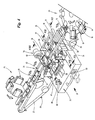
- the unit comprises in particular the glue units 34, 35; 40, 41 the drives for moving the glue units 34, 35; 40, 41 between the stations and the collecting device 49, 57 and collecting means 50, 58 and the container 62 with the cleaning rollers 59, 61st
- the drawer 71 is longitudinally displaceably mounted with double-sided rails 72 between pairs of sliding shoes 73, so that the drawer with the entire unit can be pulled laterally out of the device without the relative position of the individual members being changed relative to one another.
- the drawer is supported by strips 76 on a machine bed 77. Independently of this, the collecting means 50, 58 and the container 62 can be pulled out laterally relative to the unit.
- a detent 79 is provided which works together with the longitudinal guide of the drawer 71.
- the drawer 71 can be locked accordingly in the retracted position, for example by a corresponding locking member.
- the power supply is bundled to a distribution box 74 laterally in or on the drawer 71. From the distribution box 74 from the individual units are supplied via power lines 75 with power.
- a device for aligning folding flaps of the package 10 in the region of the lid 12 is arranged in the region of the glue units 40, 41, namely an aligner shaft 78.
- the aligning shaft 78 is arranged upstream of the glue units 40, 41, so that the cold glue is applied to the aligned folding flaps can.
- the operation of the aligner shaft 78 results from DE 100 31 319 A1 ,
- the device described so far in its essential parts functions as follows: In the event of an interruption of the operation of the device, the glue units 34, 35; 40 41 moved to the cleaning position. For the glue units 34, 35 for the application of hot glue, this means that they are moved into the cleaning position for the delivery of glue portions below the transport path 24. The glue units 40, 41 are also moved to this position. Furthermore, the glue units 40, 41 can still be moved into the second cleaning position in contact with the cleaning rollers 59. This is done in accordance with a corresponding programming of a machine control for the device. The selection of the cleaning position to be approached can be made dependent in particular on the duration of the interruption.
Landscapes
- Engineering & Computer Science (AREA)
- Mechanical Engineering (AREA)
- Wrapping Of Specific Fragile Articles (AREA)
- Making Paper Articles (AREA)
Priority Applications (1)
| Application Number | Priority Date | Filing Date | Title |
|---|---|---|---|
| PL11005128T PL2423112T3 (pl) | 2010-08-24 | 2011-06-24 | Urządzenie i sposób produkcji opakowań na papierosy |
Applications Claiming Priority (1)
| Application Number | Priority Date | Filing Date | Title |
|---|---|---|---|
| DE102010035320A DE102010035320A1 (de) | 2010-08-24 | 2010-08-24 | Vorrichtung und Verfahren zum Herstellen von Packungen für Zigaretten |
Publications (2)
| Publication Number | Publication Date |
|---|---|
| EP2423112A1 true EP2423112A1 (fr) | 2012-02-29 |
| EP2423112B1 EP2423112B1 (fr) | 2014-05-28 |
Family
ID=44925673
Family Applications (1)
| Application Number | Title | Priority Date | Filing Date |
|---|---|---|---|
| EP11005128.1A Not-in-force EP2423112B1 (fr) | 2010-08-24 | 2011-06-24 | Dispositif et procédé de fabrication d'emballages pour cigarettes |
Country Status (4)
| Country | Link |
|---|---|
| EP (1) | EP2423112B1 (fr) |
| CN (1) | CN102431211B (fr) |
| DE (1) | DE102010035320A1 (fr) |
| PL (1) | PL2423112T3 (fr) |
Cited By (6)
| Publication number | Priority date | Publication date | Assignee | Title |
|---|---|---|---|---|
| WO2015010762A1 (fr) * | 2013-07-23 | 2015-01-29 | Focke & Co. (Gmbh & Co. Kg) | Dispositif permettant de produire des emballages pour cigarettes et pourvu d'un ensemble soupape |
| IT201900000545A1 (it) * | 2019-01-14 | 2020-07-14 | Gd Spa | Procedimento e apparecchiatura per confezionare prodotti in pacchetti a forma di scatola |
| CN114618748A (zh) * | 2022-01-22 | 2022-06-14 | 红塔烟草(集团)有限责任公司 | 一种用于烟包商标纸喷涂冷热胶组合装置 |
| CN115973528A (zh) * | 2023-01-10 | 2023-04-18 | 红云红河烟草(集团)有限责任公司 | 一种用于保润保香烟包的内框纸喷胶系统 |
| CN116493193A (zh) * | 2023-05-09 | 2023-07-28 | 上海众新信息科技有限公司 | 一种超级计算机主板涂胶装置 |
| CN119079223A (zh) * | 2024-10-08 | 2024-12-06 | 广东诺倍而自动化设备有限公司 | 自动折盒装料系统 |
Families Citing this family (11)
| Publication number | Priority date | Publication date | Assignee | Title |
|---|---|---|---|---|
| CN104107790B (zh) * | 2014-07-23 | 2016-05-25 | 安阳恒安电机有限公司 | 一种电机转子片自动涂胶生产线 |
| DE102015001593A1 (de) * | 2015-02-05 | 2016-08-11 | Focke & Co. (Gmbh & Co. Kg) | Vorrichtung und Verfahren zum Herstellen von quaderförmigen Packungen für Zigaretten |
| DE102015001850A1 (de) * | 2015-02-17 | 2016-08-18 | Focke & Co. (Gmbh & Co. Kg) | Vorrichtung zum Herstellen von Packungen |
| DE202015104986U1 (de) | 2015-09-21 | 2015-10-29 | Norbert Deppe | Reinigungsvorrichtung für Leimdüsen |
| DE102015115857A1 (de) | 2015-09-21 | 2017-03-23 | Norbert Deppe | Reinigungsvorrichtung für Leimdüsen und Reinigungsverfahren |
| CN109532092B (zh) * | 2018-11-12 | 2021-01-26 | 江苏联通纪元印务股份有限公司 | 一体式烟盒成型机构 |
| CN109455335B (zh) * | 2018-11-15 | 2020-09-15 | 红塔烟草(集团)有限责任公司 | 一种异型多规格卷烟产品的商标折叠装置 |
| CN110053819B (zh) * | 2019-03-04 | 2020-09-04 | 红塔烟草(集团)有限责任公司 | 一种focke350包装机组双内包内衬纸折叠方法 |
| CN109911325A (zh) * | 2019-03-14 | 2019-06-21 | 红塔烟草(集团)有限责任公司 | 一种硬盒包装机内框纸成型定位装置 |
| CN112549640B (zh) * | 2020-11-25 | 2022-08-09 | 中烟机械技术中心有限责任公司 | 烟包盒上胶折叠装置 |
| CN115973550B (zh) * | 2023-02-02 | 2025-10-14 | 上海烟草机械有限责任公司 | 用于烟包商标纸长侧面折叠的包装装置及折叠包装方法 |
Citations (10)
| Publication number | Priority date | Publication date | Assignee | Title |
|---|---|---|---|---|
| DE19639260A1 (de) * | 1996-09-25 | 1998-03-26 | Topack Verpacktech Gmbh | Vorrichtung zum Auftragen von Leim auf Hüllmaterialzuschnitte |
| EP0844181A1 (fr) * | 1996-11-22 | 1998-05-27 | Focke & Co. (GmbH & Co.) | Dispositif pour la fabrication de paquets comportant des volets collés |
| DE19847713A1 (de) * | 1998-10-16 | 2000-04-20 | Kochsiek Maschinenbau Soltau G | Kleberauftrags- und Wartungsvorrichtung |
| DE19851775A1 (de) * | 1998-11-10 | 2000-05-11 | Focke & Co | Verpackungsmaschine für Zigaretten |
| EP1121869A1 (fr) * | 2000-01-31 | 2001-08-08 | G.D. S.p.A. | Unité de gommage |
| DE10031319A1 (de) | 2000-07-03 | 2002-01-17 | Focke & Co | Verfahren und Vorrichtung zum Herstellen von Klappschachteln mit Schließhilfe |
| EP1219540A1 (fr) * | 2000-12-22 | 2002-07-03 | G.D Societ Per Azioni | Procédé, dispositif et installation de gommage d' articles |
| EP1232800A1 (fr) * | 2001-02-14 | 2002-08-21 | G.D S.p.A. | Dispositif de collage par pulvérisateur |
| EP1842599A2 (fr) * | 2006-04-04 | 2007-10-10 | Baumer hhs GmbH | Procédé et dispositif destinés au nettoyage d'au moins une unité d'application comportant une ouverture de sortie de fluide pour l'application d'un fluide |
| DE102008029929A1 (de) * | 2008-06-26 | 2009-12-31 | Focke & Co.(Gmbh & Co. Kg) | Verfahren und Vorrichtung zum Herstellen von Packungen |
Family Cites Families (3)
| Publication number | Priority date | Publication date | Assignee | Title |
|---|---|---|---|---|
| IT1311388B1 (it) * | 1999-11-10 | 2002-03-12 | Gd Spa | Unita' di gommatura a spruzzo. |
| ITBO20000578A1 (it) * | 2000-10-06 | 2002-04-06 | Gd Spa | Dispositivo dispensatore di fluidi essicabili |
| IT1394943B1 (it) * | 2009-04-17 | 2012-07-27 | Gima Spa | Dispositivo per il confezionamento di un prodotto in un corrispondente contenitore |
-
2010
- 2010-08-24 DE DE102010035320A patent/DE102010035320A1/de not_active Withdrawn
-
2011
- 2011-06-24 EP EP11005128.1A patent/EP2423112B1/fr not_active Not-in-force
- 2011-06-24 PL PL11005128T patent/PL2423112T3/pl unknown
- 2011-08-23 CN CN201110242008.5A patent/CN102431211B/zh not_active Expired - Fee Related
Patent Citations (10)
| Publication number | Priority date | Publication date | Assignee | Title |
|---|---|---|---|---|
| DE19639260A1 (de) * | 1996-09-25 | 1998-03-26 | Topack Verpacktech Gmbh | Vorrichtung zum Auftragen von Leim auf Hüllmaterialzuschnitte |
| EP0844181A1 (fr) * | 1996-11-22 | 1998-05-27 | Focke & Co. (GmbH & Co.) | Dispositif pour la fabrication de paquets comportant des volets collés |
| DE19847713A1 (de) * | 1998-10-16 | 2000-04-20 | Kochsiek Maschinenbau Soltau G | Kleberauftrags- und Wartungsvorrichtung |
| DE19851775A1 (de) * | 1998-11-10 | 2000-05-11 | Focke & Co | Verpackungsmaschine für Zigaretten |
| EP1121869A1 (fr) * | 2000-01-31 | 2001-08-08 | G.D. S.p.A. | Unité de gommage |
| DE10031319A1 (de) | 2000-07-03 | 2002-01-17 | Focke & Co | Verfahren und Vorrichtung zum Herstellen von Klappschachteln mit Schließhilfe |
| EP1219540A1 (fr) * | 2000-12-22 | 2002-07-03 | G.D Societ Per Azioni | Procédé, dispositif et installation de gommage d' articles |
| EP1232800A1 (fr) * | 2001-02-14 | 2002-08-21 | G.D S.p.A. | Dispositif de collage par pulvérisateur |
| EP1842599A2 (fr) * | 2006-04-04 | 2007-10-10 | Baumer hhs GmbH | Procédé et dispositif destinés au nettoyage d'au moins une unité d'application comportant une ouverture de sortie de fluide pour l'application d'un fluide |
| DE102008029929A1 (de) * | 2008-06-26 | 2009-12-31 | Focke & Co.(Gmbh & Co. Kg) | Verfahren und Vorrichtung zum Herstellen von Packungen |
Cited By (9)
| Publication number | Priority date | Publication date | Assignee | Title |
|---|---|---|---|---|
| WO2015010762A1 (fr) * | 2013-07-23 | 2015-01-29 | Focke & Co. (Gmbh & Co. Kg) | Dispositif permettant de produire des emballages pour cigarettes et pourvu d'un ensemble soupape |
| IT201900000545A1 (it) * | 2019-01-14 | 2020-07-14 | Gd Spa | Procedimento e apparecchiatura per confezionare prodotti in pacchetti a forma di scatola |
| EP3680184A1 (fr) * | 2019-01-14 | 2020-07-15 | G.D S.p.A. | Procédé et appareil pour emballer des produits dans des emballages en forme de boîte |
| EP3680184B1 (fr) | 2019-01-14 | 2021-09-01 | G.D S.p.A. | Procédé et appareil pour emballer des produits dans des emballages en forme de boîte |
| CN114618748A (zh) * | 2022-01-22 | 2022-06-14 | 红塔烟草(集团)有限责任公司 | 一种用于烟包商标纸喷涂冷热胶组合装置 |
| CN114618748B (zh) * | 2022-01-22 | 2023-03-10 | 红塔烟草(集团)有限责任公司 | 一种用于烟包商标纸喷涂冷热胶组合装置 |
| CN115973528A (zh) * | 2023-01-10 | 2023-04-18 | 红云红河烟草(集团)有限责任公司 | 一种用于保润保香烟包的内框纸喷胶系统 |
| CN116493193A (zh) * | 2023-05-09 | 2023-07-28 | 上海众新信息科技有限公司 | 一种超级计算机主板涂胶装置 |
| CN119079223A (zh) * | 2024-10-08 | 2024-12-06 | 广东诺倍而自动化设备有限公司 | 自动折盒装料系统 |
Also Published As
| Publication number | Publication date |
|---|---|
| PL2423112T3 (pl) | 2014-09-30 |
| DE102010035320A1 (de) | 2012-03-01 |
| EP2423112B1 (fr) | 2014-05-28 |
| CN102431211A (zh) | 2012-05-02 |
| CN102431211B (zh) | 2014-09-17 |
Similar Documents
| Publication | Publication Date | Title |
|---|---|---|
| EP2423112B1 (fr) | Dispositif et procédé de fabrication d'emballages pour cigarettes | |
| EP0386524B1 (fr) | Dispositif d'emballage d'objets de différentes dimensions | |
| EP0920919B1 (fr) | Boíte à couvercle articulé pour cigarettes et méthode et appareil pour l'encollage de matériau d'emballage | |
| EP0612481B1 (fr) | Dispositif pour le transport et l'approvisionnement de cigarettes | |
| DE102014103671B3 (de) | Behälterbehandlungsmaschine sowie Verfahren zum Zu- und/oder Abführen von Behältern zu einer Behälterbehandlungsmaschine | |
| DE2500569A1 (de) | Verpackungsmaschine | |
| EP0604808A1 (fr) | Machine d'emballage | |
| EP0113899B1 (fr) | Procédé et dispositif pour la fermeture de cartons | |
| EP0413927B1 (fr) | Installation pour fabriquer des emballages pour des produits liquides | |
| WO2012104251A1 (fr) | Dispositif et procédé d'étiquetage d'emballages individuels depuis le côté inférieur de l'emballage | |
| DE3800664A1 (de) | Verfahren und vorrichtung zum herstellen von einen kragen aufweisenden klappschachteln, insbesondere fuer zigaretten | |
| EP3315420A1 (fr) | Machine d'emballage par emboutissage | |
| EP0329056B1 (fr) | Procédé et dispositif pour alimenter des bandelettes à une machine d'emballage | |
| DE19648445A1 (de) | Vorrichtung zum Herstellen von Packungen mit verleimten Faltlappen | |
| EP1403187A1 (fr) | Machine d'emballage avec dispositif de nettoyage | |
| WO2003064270A2 (fr) | Procede et dispositif pour la production de groupes d'emballage pour des cigarettes | |
| EP3583064A1 (fr) | Machine de remplissage et procédé de remplissage d'emballages avec un produit fluide | |
| EP0531872B1 (fr) | Appareil pour transporter des bouteilles en plastiques dans une machine de lavage de bouteilles | |
| DE102005023983B4 (de) | Etikettiermaschine für Behälter | |
| WO2007090514A1 (fr) | Dispositif de manipulation d'objets plats et en particulier de couches-culottes | |
| WO2023016693A1 (fr) | Appareil et procédé de fabrication d'emballages composites carton/plastique remplis | |
| EP1028057B1 (fr) | Station de remplissage pour machine de formage, de remplissage et de scellement d'emballages | |
| EP2642019B1 (fr) | Procédé d'amenée de pièces de linge vers une repasseuse ou analogue | |
| EP1937560B1 (fr) | Dispositif d'étiquetage de pots formés dans une bande de matériau d'emballage | |
| DE4209151C2 (de) | Vorrichtung zur Bearbeitung von faltbaren Verpackungszuschnitten, insbesondere zur Herstellung von Flaschenkartons |
Legal Events
| Date | Code | Title | Description |
|---|---|---|---|
| AK | Designated contracting states |
Kind code of ref document: A1 Designated state(s): AL AT BE BG CH CY CZ DE DK EE ES FI FR GB GR HR HU IE IS IT LI LT LU LV MC MK MT NL NO PL PT RO RS SE SI SK SM TR |
|
| AX | Request for extension of the european patent |
Extension state: BA ME |
|
| PUAI | Public reference made under article 153(3) epc to a published international application that has entered the european phase |
Free format text: ORIGINAL CODE: 0009012 |
|
| 17P | Request for examination filed |
Effective date: 20120419 |
|
| 17Q | First examination report despatched |
Effective date: 20130102 |
|
| GRAP | Despatch of communication of intention to grant a patent |
Free format text: ORIGINAL CODE: EPIDOSNIGR1 |
|
| INTG | Intention to grant announced |
Effective date: 20131218 |
|
| GRAS | Grant fee paid |
Free format text: ORIGINAL CODE: EPIDOSNIGR3 |
|
| GRAA | (expected) grant |
Free format text: ORIGINAL CODE: 0009210 |
|
| AK | Designated contracting states |
Kind code of ref document: B1 Designated state(s): AL AT BE BG CH CY CZ DE DK EE ES FI FR GB GR HR HU IE IS IT LI LT LU LV MC MK MT NL NO PL PT RO RS SE SI SK SM TR |
|
| REG | Reference to a national code |
Ref country code: GB Ref legal event code: FG4D Free format text: NOT ENGLISH |
|
| REG | Reference to a national code |
Ref country code: CH Ref legal event code: EP |
|
| REG | Reference to a national code |
Ref country code: AT Ref legal event code: REF Ref document number: 670271 Country of ref document: AT Kind code of ref document: T Effective date: 20140615 |
|
| REG | Reference to a national code |
Ref country code: IE Ref legal event code: FG4D Free format text: LANGUAGE OF EP DOCUMENT: GERMAN |
|
| REG | Reference to a national code |
Ref country code: DE Ref legal event code: R096 Ref document number: 502011003225 Country of ref document: DE Effective date: 20140710 |
|
| REG | Reference to a national code |
Ref country code: PL Ref legal event code: T3 |
|
| REG | Reference to a national code |
Ref country code: NL Ref legal event code: VDEP Effective date: 20140528 |
|
| REG | Reference to a national code |
Ref country code: LT Ref legal event code: MG4D |
|
| PG25 | Lapsed in a contracting state [announced via postgrant information from national office to epo] |
Ref country code: GR Free format text: LAPSE BECAUSE OF FAILURE TO SUBMIT A TRANSLATION OF THE DESCRIPTION OR TO PAY THE FEE WITHIN THE PRESCRIBED TIME-LIMIT Effective date: 20140829 Ref country code: LT Free format text: LAPSE BECAUSE OF FAILURE TO SUBMIT A TRANSLATION OF THE DESCRIPTION OR TO PAY THE FEE WITHIN THE PRESCRIBED TIME-LIMIT Effective date: 20140528 Ref country code: CY Free format text: LAPSE BECAUSE OF FAILURE TO SUBMIT A TRANSLATION OF THE DESCRIPTION OR TO PAY THE FEE WITHIN THE PRESCRIBED TIME-LIMIT Effective date: 20140528 Ref country code: NO Free format text: LAPSE BECAUSE OF FAILURE TO SUBMIT A TRANSLATION OF THE DESCRIPTION OR TO PAY THE FEE WITHIN THE PRESCRIBED TIME-LIMIT Effective date: 20140828 Ref country code: FI Free format text: LAPSE BECAUSE OF FAILURE TO SUBMIT A TRANSLATION OF THE DESCRIPTION OR TO PAY THE FEE WITHIN THE PRESCRIBED TIME-LIMIT Effective date: 20140528 |
|
| PG25 | Lapsed in a contracting state [announced via postgrant information from national office to epo] |
Ref country code: RS Free format text: LAPSE BECAUSE OF FAILURE TO SUBMIT A TRANSLATION OF THE DESCRIPTION OR TO PAY THE FEE WITHIN THE PRESCRIBED TIME-LIMIT Effective date: 20140528 Ref country code: SE Free format text: LAPSE BECAUSE OF FAILURE TO SUBMIT A TRANSLATION OF THE DESCRIPTION OR TO PAY THE FEE WITHIN THE PRESCRIBED TIME-LIMIT Effective date: 20140528 Ref country code: HR Free format text: LAPSE BECAUSE OF FAILURE TO SUBMIT A TRANSLATION OF THE DESCRIPTION OR TO PAY THE FEE WITHIN THE PRESCRIBED TIME-LIMIT Effective date: 20140528 Ref country code: LV Free format text: LAPSE BECAUSE OF FAILURE TO SUBMIT A TRANSLATION OF THE DESCRIPTION OR TO PAY THE FEE WITHIN THE PRESCRIBED TIME-LIMIT Effective date: 20140528 |
|
| PG25 | Lapsed in a contracting state [announced via postgrant information from national office to epo] |
Ref country code: PT Free format text: LAPSE BECAUSE OF FAILURE TO SUBMIT A TRANSLATION OF THE DESCRIPTION OR TO PAY THE FEE WITHIN THE PRESCRIBED TIME-LIMIT Effective date: 20140929 |
|
| PG25 | Lapsed in a contracting state [announced via postgrant information from national office to epo] |
Ref country code: EE Free format text: LAPSE BECAUSE OF FAILURE TO SUBMIT A TRANSLATION OF THE DESCRIPTION OR TO PAY THE FEE WITHIN THE PRESCRIBED TIME-LIMIT Effective date: 20140528 Ref country code: RO Free format text: LAPSE BECAUSE OF FAILURE TO SUBMIT A TRANSLATION OF THE DESCRIPTION OR TO PAY THE FEE WITHIN THE PRESCRIBED TIME-LIMIT Effective date: 20140528 Ref country code: CZ Free format text: LAPSE BECAUSE OF FAILURE TO SUBMIT A TRANSLATION OF THE DESCRIPTION OR TO PAY THE FEE WITHIN THE PRESCRIBED TIME-LIMIT Effective date: 20140528 Ref country code: DK Free format text: LAPSE BECAUSE OF FAILURE TO SUBMIT A TRANSLATION OF THE DESCRIPTION OR TO PAY THE FEE WITHIN THE PRESCRIBED TIME-LIMIT Effective date: 20140528 Ref country code: ES Free format text: LAPSE BECAUSE OF FAILURE TO SUBMIT A TRANSLATION OF THE DESCRIPTION OR TO PAY THE FEE WITHIN THE PRESCRIBED TIME-LIMIT Effective date: 20140528 Ref country code: SK Free format text: LAPSE BECAUSE OF FAILURE TO SUBMIT A TRANSLATION OF THE DESCRIPTION OR TO PAY THE FEE WITHIN THE PRESCRIBED TIME-LIMIT Effective date: 20140528 |
|
| REG | Reference to a national code |
Ref country code: CH Ref legal event code: PL |
|
| PG25 | Lapsed in a contracting state [announced via postgrant information from national office to epo] |
Ref country code: NL Free format text: LAPSE BECAUSE OF FAILURE TO SUBMIT A TRANSLATION OF THE DESCRIPTION OR TO PAY THE FEE WITHIN THE PRESCRIBED TIME-LIMIT Effective date: 20140528 |
|
| REG | Reference to a national code |
Ref country code: DE Ref legal event code: R097 Ref document number: 502011003225 Country of ref document: DE |
|
| REG | Reference to a national code |
Ref country code: IE Ref legal event code: MM4A |
|
| PLBE | No opposition filed within time limit |
Free format text: ORIGINAL CODE: 0009261 |
|
| STAA | Information on the status of an ep patent application or granted ep patent |
Free format text: STATUS: NO OPPOSITION FILED WITHIN TIME LIMIT |
|
| PG25 | Lapsed in a contracting state [announced via postgrant information from national office to epo] |
Ref country code: CH Free format text: LAPSE BECAUSE OF NON-PAYMENT OF DUE FEES Effective date: 20140630 Ref country code: IE Free format text: LAPSE BECAUSE OF NON-PAYMENT OF DUE FEES Effective date: 20140624 Ref country code: LI Free format text: LAPSE BECAUSE OF NON-PAYMENT OF DUE FEES Effective date: 20140630 |
|
| 26N | No opposition filed |
Effective date: 20150303 |
|
| REG | Reference to a national code |
Ref country code: FR Ref legal event code: ST Effective date: 20150407 |
|
| PG25 | Lapsed in a contracting state [announced via postgrant information from national office to epo] |
Ref country code: FR Free format text: LAPSE BECAUSE OF NON-PAYMENT OF DUE FEES Effective date: 20140728 |
|
| REG | Reference to a national code |
Ref country code: DE Ref legal event code: R097 Ref document number: 502011003225 Country of ref document: DE Effective date: 20150303 |
|
| PG25 | Lapsed in a contracting state [announced via postgrant information from national office to epo] |
Ref country code: SI Free format text: LAPSE BECAUSE OF FAILURE TO SUBMIT A TRANSLATION OF THE DESCRIPTION OR TO PAY THE FEE WITHIN THE PRESCRIBED TIME-LIMIT Effective date: 20140528 |
|
| PG25 | Lapsed in a contracting state [announced via postgrant information from national office to epo] |
Ref country code: MT Free format text: LAPSE BECAUSE OF FAILURE TO SUBMIT A TRANSLATION OF THE DESCRIPTION OR TO PAY THE FEE WITHIN THE PRESCRIBED TIME-LIMIT Effective date: 20140528 |
|
| PG25 | Lapsed in a contracting state [announced via postgrant information from national office to epo] |
Ref country code: MC Free format text: LAPSE BECAUSE OF FAILURE TO SUBMIT A TRANSLATION OF THE DESCRIPTION OR TO PAY THE FEE WITHIN THE PRESCRIBED TIME-LIMIT Effective date: 20140528 Ref country code: SM Free format text: LAPSE BECAUSE OF FAILURE TO SUBMIT A TRANSLATION OF THE DESCRIPTION OR TO PAY THE FEE WITHIN THE PRESCRIBED TIME-LIMIT Effective date: 20140528 |
|
| PG25 | Lapsed in a contracting state [announced via postgrant information from national office to epo] |
Ref country code: BG Free format text: LAPSE BECAUSE OF FAILURE TO SUBMIT A TRANSLATION OF THE DESCRIPTION OR TO PAY THE FEE WITHIN THE PRESCRIBED TIME-LIMIT Effective date: 20140528 Ref country code: IS Free format text: LAPSE BECAUSE OF FAILURE TO SUBMIT A TRANSLATION OF THE DESCRIPTION OR TO PAY THE FEE WITHIN THE PRESCRIBED TIME-LIMIT Effective date: 20140528 |
|
| PG25 | Lapsed in a contracting state [announced via postgrant information from national office to epo] |
Ref country code: TR Free format text: LAPSE BECAUSE OF FAILURE TO SUBMIT A TRANSLATION OF THE DESCRIPTION OR TO PAY THE FEE WITHIN THE PRESCRIBED TIME-LIMIT Effective date: 20140528 Ref country code: HU Free format text: LAPSE BECAUSE OF FAILURE TO SUBMIT A TRANSLATION OF THE DESCRIPTION OR TO PAY THE FEE WITHIN THE PRESCRIBED TIME-LIMIT; INVALID AB INITIO Effective date: 20110624 Ref country code: BE Free format text: LAPSE BECAUSE OF FAILURE TO SUBMIT A TRANSLATION OF THE DESCRIPTION OR TO PAY THE FEE WITHIN THE PRESCRIBED TIME-LIMIT Effective date: 20140630 Ref country code: LU Free format text: LAPSE BECAUSE OF NON-PAYMENT OF DUE FEES Effective date: 20140624 |
|
| PG25 | Lapsed in a contracting state [announced via postgrant information from national office to epo] |
Ref country code: AT Free format text: LAPSE BECAUSE OF FAILURE TO SUBMIT A TRANSLATION OF THE DESCRIPTION OR TO PAY THE FEE WITHIN THE PRESCRIBED TIME-LIMIT Effective date: 20140528 |
|
| REG | Reference to a national code |
Ref country code: AT Ref legal event code: MM01 Ref document number: 670271 Country of ref document: AT Kind code of ref document: T Effective date: 20160624 |
|
| PG25 | Lapsed in a contracting state [announced via postgrant information from national office to epo] |
Ref country code: AT Free format text: LAPSE BECAUSE OF FAILURE TO SUBMIT A TRANSLATION OF THE DESCRIPTION OR TO PAY THE FEE WITHIN THE PRESCRIBED TIME-LIMIT Effective date: 20160624 |
|
| PG25 | Lapsed in a contracting state [announced via postgrant information from national office to epo] |
Ref country code: MK Free format text: LAPSE BECAUSE OF FAILURE TO SUBMIT A TRANSLATION OF THE DESCRIPTION OR TO PAY THE FEE WITHIN THE PRESCRIBED TIME-LIMIT Effective date: 20140528 |
|
| PG25 | Lapsed in a contracting state [announced via postgrant information from national office to epo] |
Ref country code: AL Free format text: LAPSE BECAUSE OF FAILURE TO SUBMIT A TRANSLATION OF THE DESCRIPTION OR TO PAY THE FEE WITHIN THE PRESCRIBED TIME-LIMIT Effective date: 20140528 |
|
| PGFP | Annual fee paid to national office [announced via postgrant information from national office to epo] |
Ref country code: DE Payment date: 20200528 Year of fee payment: 10 |
|
| PGFP | Annual fee paid to national office [announced via postgrant information from national office to epo] |
Ref country code: GB Payment date: 20200617 Year of fee payment: 10 Ref country code: PL Payment date: 20200605 Year of fee payment: 10 |
|
| REG | Reference to a national code |
Ref country code: DE Ref legal event code: R119 Ref document number: 502011003225 Country of ref document: DE |
|
| GBPC | Gb: european patent ceased through non-payment of renewal fee |
Effective date: 20210624 |
|
| PG25 | Lapsed in a contracting state [announced via postgrant information from national office to epo] |
Ref country code: GB Free format text: LAPSE BECAUSE OF NON-PAYMENT OF DUE FEES Effective date: 20210624 Ref country code: DE Free format text: LAPSE BECAUSE OF NON-PAYMENT OF DUE FEES Effective date: 20220101 |
|
| P01 | Opt-out of the competence of the unified patent court (upc) registered |
Effective date: 20230517 |
|
| PGFP | Annual fee paid to national office [announced via postgrant information from national office to epo] |
Ref country code: IT Payment date: 20230526 Year of fee payment: 13 |
|
| PG25 | Lapsed in a contracting state [announced via postgrant information from national office to epo] |
Ref country code: PL Free format text: LAPSE BECAUSE OF NON-PAYMENT OF DUE FEES Effective date: 20210624 |
|
| PG25 | Lapsed in a contracting state [announced via postgrant information from national office to epo] |
Ref country code: IT Free format text: LAPSE BECAUSE OF NON-PAYMENT OF DUE FEES Effective date: 20240624 |