EP2423472B1 - Système et procédé de cycle de Rankine organique - Google Patents
Système et procédé de cycle de Rankine organique Download PDFInfo
- Publication number
- EP2423472B1 EP2423472B1 EP10161924.5A EP10161924A EP2423472B1 EP 2423472 B1 EP2423472 B1 EP 2423472B1 EP 10161924 A EP10161924 A EP 10161924A EP 2423472 B1 EP2423472 B1 EP 2423472B1
- Authority
- EP
- European Patent Office
- Prior art keywords
- fluid
- temperature
- waste heat
- evaporator
- working fluid
- Prior art date
- Legal status (The legal status is an assumption and is not a legal conclusion. Google has not performed a legal analysis and makes no representation as to the accuracy of the status listed.)
- Active
Links
Images

Classifications
-
- F—MECHANICAL ENGINEERING; LIGHTING; HEATING; WEAPONS; BLASTING
- F01—MACHINES OR ENGINES IN GENERAL; ENGINE PLANTS IN GENERAL; STEAM ENGINES
- F01K—STEAM ENGINE PLANTS; STEAM ACCUMULATORS; ENGINE PLANTS NOT OTHERWISE PROVIDED FOR; ENGINES USING SPECIAL WORKING FLUIDS OR CYCLES
- F01K23/00—Plants characterised by more than one engine delivering power external to the plant, the engines being driven by different fluids
- F01K23/02—Plants characterised by more than one engine delivering power external to the plant, the engines being driven by different fluids the engine cycles being thermally coupled
- F01K23/06—Plants characterised by more than one engine delivering power external to the plant, the engines being driven by different fluids the engine cycles being thermally coupled combustion heat from one cycle heating the fluid in another cycle
- F01K23/10—Plants characterised by more than one engine delivering power external to the plant, the engines being driven by different fluids the engine cycles being thermally coupled combustion heat from one cycle heating the fluid in another cycle with exhaust fluid of one cycle heating the fluid in another cycle
-
- F—MECHANICAL ENGINEERING; LIGHTING; HEATING; WEAPONS; BLASTING
- F01—MACHINES OR ENGINES IN GENERAL; ENGINE PLANTS IN GENERAL; STEAM ENGINES
- F01K—STEAM ENGINE PLANTS; STEAM ACCUMULATORS; ENGINE PLANTS NOT OTHERWISE PROVIDED FOR; ENGINES USING SPECIAL WORKING FLUIDS OR CYCLES
- F01K25/00—Plants or engines characterised by use of special working fluids, not otherwise provided for; Plants operating in closed cycles and not otherwise provided for
- F01K25/08—Plants or engines characterised by use of special working fluids, not otherwise provided for; Plants operating in closed cycles and not otherwise provided for using special vapours
Definitions
- the invention relates generally to organic rankine cycle (ORC) systems, and more particularly to an economical system and method for the same.
- rankine cycle systems have been used to capture the so called "waste heat,” that was otherwise being lost to the atmosphere and, as such, was indirectly detrimental to the environment by requiring more fuel for power production than necessary.
- ORC systems have been deployed as retrofits for small and medium-scale gas turbines, to capture from the waste heat gas stream desirable power output.
- a working fluid used in such cycles is typically a hydrocarbon at about atmospheric pressure.
- the working fluid may degrade beyond a critical temperature, such as, but not limited to, 500 deg C.
- the temperature of the exhaust is comparable to such high temperatures and hence, there is a reasonable probability of degradation of the working fluid due to direct exposure to the waste heat gas from the exhaust.
- an intermediate thermal fluid system is generally used to convey heat from the exhaust to an organic Rankine cycle boiler.
- the fluid is oil.
- the intermediate thermal fluid system represents up to about one-quarter of the cost of the complete ORC.
- the intermediate thermal fluid system and heat exchangers require a higher temperature difference resulting in an increase in size and a lowering of the overall efficiency. Therefore, an improved ORC system is desirable to address one or more of the aforementioned issues.
- the heat recovery steam generator comprises a high-temperature evaporator, a superheater, an evaporator and an economizer which are arranged in a steel container in series.
- the high-temperature evaporator is designed to adopt a fire-tube structure, wherein the subsequently arranged superheater, evaporator and economizer are designed to adopt a water-tube structure.
- Document JPH06213403 A describes a waste heat recovery boiler taking as a heat source combustion gas exhausted from a gas turbine device. Further, document WO 2006/050714 A2 teaches a device for transforming a working medium from a liquid to a vapor state. The device comprises a spiral flow channel through which the working medium flows and a heat source arranged in the centre of the spiral flow channel.
- an ORC system configured to limit temperature of a working fluid below a threshold temperature.
- the ORC system includes a heat source configured to convey a waste heat fluid.
- the ORC system also includes a heat exchanger coupled to the heat source.
- the heat exchanger includes an evaporator configured to receive the waste heat fluid from the heat source and vaporize the working fluid, wherein the evaporator is further configured to allow heat exchange between the waste heat fluid and the vaporized working fluid and produce an evaporator outlet flow comprising a lower temperature waste heat fluid.
- the heat exchanger also includes a superheater configured to receive the lower temperature waste heat fluid from the evaporator and is further configured to allow heat exchange between the lower temperature waste heat fluid and a relatively higher temperature working fluid contained in the superheater and further produce a superheater outlet flow comprising an elevated temperature waste heat fluid.
- the heat exchanger further includes a preheater configured to receive the elevated temperature waste heat fluid from the superheater and allow heat exchange with a relatively lower temperature working fluid in a liquid state contained in the preheater.
- a method for limiting temperature of a working fluid below a threshold temperature in an ORC includes introducing waste heat fluid into a heat exchanger, wherein the heat exchanger includes an evaporator, a superheater and a preheater. The method also includes conveying the waste heat fluid into the evaporator to promote heat exchange between the waste heat fluid and the working fluid at an elevated temperature vaporized within the evaporator to produce an evaporator outlet flow including a lower temperature waste heat fluid.
- the method also includes conveying the lower temperature waste heat fluid from the evaporator to a superheater to promote heat exchange between the lower temperature waste heat fluid and a relatively higher temperature working fluid contained in the superheater and further producing a superheater outlet flow including an elevated temperature waste heat fluid.
- the method further includes conveying the elevated temperature waste heat fluid from the superheater to a preheater to promote heat exchange with a relatively lower temperature working fluid in a liquid state contained in the preheater.
- embodiments of the invention include an organic rankine cycle (ORC) system and method to limit the temperature of a working fluid within the system, below a threshold temperature.
- ORC organic rankine cycle
- the system and method provide a waste heat fluid that flows into various sections of a heat exchanger to enable optimal heat exchange between the waste heat fluid and the working fluid thereby avoiding overheating of the working fluid.
- the heat exchanger includes external and internal enhancement features to provide optimal heat exchange between the waste heat fluid and the working fluid.
- the term 'threshold temperature' refers to temperatures in a range between about 250 to about 350 deg C.
- FIG. 1 is a schematic illustration of an organic rankine cycle (ORC) system 10 configured to limit the temperature of a working fluid 14 below a threshold temperature.
- the system 10 includes a heat source 16 that conveys a waste heat fluid 18 at a temperature, for example, between about 400 to about 600 deg C.
- a heat exchanger 20 is coupled to the heat source 16 and is configured to facilitate heat exchange between the working fluid 14 and the waste heat fluid 18 in a manner that does not overheat the working fluid 14, as will be discussed in greater detail below.
- the heat exchanger 20 includes an evaporator 22 that receives an inflow of the working fluid 14 and vaporizes the working fluid 14.
- the evaporator 22 receives the waste heat fluid 18 from the heat source 16 and promotes heat exchange between the waste heat fluid 18 and the working fluid 14 that is at a relatively lower temperature, for example between about 150 deg C to about 300 deg C and produces an evaporator outlet flow including a lower temperature waste heat fluid 23 and an elevated temperature working fluid 25.
- the temperature of the elevated temperature working fluid 25 exiting the evaporator 22 is about 230 deg C.
- the waste heat fluid 18 and the working fluid 25 are in parallel flow configuration in the evaporator 22.
- the term 'parallel flow configuration' refers to heat being transferred from an inlet of the heat source 16 to an inlet of the evaporator 22 and likewise, from an outlet of the heat source 16 to an outlet of the evaporator 22.
- the evaporator outlet flow from the evaporator 22 is conveyed to a superheater 24.
- the superheater 24 further heats the elevated temperature working fluid 25 to produce a working fluid 29 at a relatively higher temperature within the heat exchanger 20 compared to the temperatures of the working fluid at the evaporator 22 and a preheater 28.
- the superheater 24 promotes heat exchange between the relatively higher temperature working fluid 25 and the lower temperature waste heat fluid 23 to produce a superheater outlet flow including an elevated temperature waste heat fluid 27. It should be noted that the waste fluid 18 directly from the heat source 16 is at a higher temperature compared to the lower temperature waste heat fluid 23 entering the superheater 24.
- the elevated temperature waste heat fluid 27 exits from the superheater 24 and is conveyed to the preheater 28.
- temperature of the elevated temperature waste heat fluid 27 exiting the superheater is between about 375 to about 425 deg C.
- the preheater 28 contains a relatively lower temperature working fluid 14 in a liquid state and promotes heat exchange between the relatively lower temperature working fluid 14 and the elevated temperature waste fluid 27 resulting in a relatively lower temperature waste fluid 31 exiting the heat exchanger 20.
- the relatively lower temperature working fluid 14 and the elevated temperature waste fluid 27 are in a counter-flow configuration in the preheater 28.
- the working fluid 14 is a hydrocarbon.
- Non-limiting examples of the hydrocarbon include at least one selected from a group of cyclopentane, n-pentane, propane, butane, n-hexane, and cyclohexane.
- the heat source includes an exhaust of a gas turbine.
- the waste heat fluid is in a gaseous state.
- FIG. 2 is a graphical illustration 50 of temperatures 52 of a waste heat fluid, the film temperatures 54 of a working fluid, and bulk temperatures 56 of the working fluid in the preheater, evaporator and superheater sections of a heat exchanger employing the flow arrangement in FIG. 1 .
- the graphical illustration 50 is a result of simulation.
- X-axis 51 represents flow length as a fraction of the total length of the heat exchanger, while Y-axis 53 represents temperatures in deg C.
- temperatures 52 of the waste heat fluid increases from about 100 deg C at minimal flow length at the preheater section 58 to about 510 deg C at a flow length of 1 unit at the superheater 62 section.
- the film temperatures 54 of the working fluid in contact with the waste heat fluid increase from about 80 deg C at preheater 58 to vary between about 244 deg C to about 273 deg C in the evaporator 60, and further to reach a temperature of about 240 deg C at the superheater 62, which is well below a threshold temperature of the working fluid.
- the bulk temperatures 56 of the working fluid also increase from about 71 deg C in the preheater to vary between about 233 deg C and 231 deg C in the evaporator, and further reach a temperature of about 240 deg C in the superheater.
- a narrower gap between the bulk temperature and film temperature of the working fluid, especially in the superheater section, is clearly indicative of a greater stability of the film temperature in the superheater and limiting of the temperature to a safe limit.
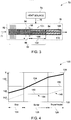
- FIG. 3 is a schematic illustration of an embodiment of an ORC system 70 to limit temperature of a working fluid 71 below a threshold temperature, showing a detailed view of a heat exchanger 78.
- a heat source 74 introduces waste heat fluid 76 into the heat exchanger 78.
- the heat exchanger 78 includes multiple external 82 and internal 84 enhancement features.
- the features include fins.
- the external enhancement features are configured to reduce a first heat transfer coefficient between the working fluid 71 and the waste heat fluid 76, external to the heat exchanger 78.
- a non-limiting example of external enhancement feature includes fins.
- the internal enhancement features are configured to increase a second heat transfer coefficient between the working fluid 71 and the waste heat 76, internal to the heat exchanger 78.
- Non-limiting examples of the internal enhancement features include internal fins, turbulators or boiling surfaces.
- the heat exchanger 78 includes a preheater, an evaporator, and a superheater.
- the working fluid 71 enters a preheater 92 in a liquid state.
- the preheater 92 includes fins 93 external and uniformly spaced at equal lengths relative to each other.
- the working fluid 71 enters an evaporator 94.
- a portion 96 of the evaporator 94 includes fins 98 external at lengths shorter than that at the preheater 92 and uniformly spaced.
- a portion 102 of the evaporator includes external fins 104 and internal fins 106.
- the external fins 104 are at shorter lengths than that of the fins 98 and are typically uniformly spaced.
- the internal fins 106 are disposed to increase a first heat transfer coefficient between the working fluid 71 and the waste heat fluid 76, while reducing a wall temperature of the evaporator experienced by a film of the working fluid 71.
- the first heat transfer coefficient ranges between about 3000 to about 5000 W/m 2- K on the fluid side, and has a value of approximately 100 W/m 2 -K on the side of the waste heat fluid, in the embodiment in which that fluid is a gas.
- the area of the fins is reduced in sections of the heat exchanger 78 where the working fluid 71 is vulnerable to overheating.
- the area of the fins is increased in sections where the working fluid 71 is not vulnerable to overheating and to reduce a second heat transfer coefficient external to the heat exchanger 78.
- the second transfer coefficient ranges between about 20000 to about 40000 W/m 2 -K on the fluid side, and has a value of approximately 100 W/m 2 -K on the side of the waste heat fluid, in the embodiment in which that fluid is a gas.
- few or no external fins are disposed in a superheater 108, while internal fins 110 may be disposed.
- a third heat transfer coefficient, on the working-fluid side of the superheater has a value of approximately 15000 W/m 2 -K.
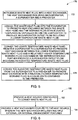
- FIG. 4 is a schematic graphical illustration 120 of exemplary temperatures of a working fluid in a preheater, evaporator and a superheater of a heat exchanger 78 ( FIG. 3 ).
- the X-axis 122 represents various sections of the heat exchanger, specifically, the preheater 124 (also referred to as 'eco' in FIG. 4 ), evaporator 126 (also referred to as 'boiler' in FIG. 4 ), and superheater 128.
- the Y-axis 130 represents temperature in deg C.
- Curve 134 represents temperature of a waste heat fluid from an exhaust.
- the temperature at an exhaust outlet increases steeply across the preheater, evaporator and superheater at an exhaust outlet location, represented by reference numeral 138.
- curve 140 represents temperature of the working fluid increasing starting from an inlet of the working fluid, represented by reference numeral 142, in a preheater 124, to reaching a steady state 144 in the evaporator 126, and further increasing slightly, as shown by 146, in the superheater 128. It should be noted that the temperature of the working fluid is maintained below a threshold temperature, indicated by horizontal line 150, in the evaporator and superheater.
- FIG. 5 is a flow chart representing steps in an exemplary method 170 for limiting temperature of a working fluid below a threshold temperature in an ORC system.
- the method 170 includes introducing waste heat fluid into a heat exchanger in step 172, wherein the heat exchanger includes an evaporator, a superheater and a preheater.
- the waste heat fluid is conveyed into the evaporator in step 174 to promote heat exchange between the waste heat fluid and the working fluid at an elevated temperature vaporized within the evaporator to produce an evaporator outlet flow including a lower temperature waste heat fluid.
- the waste heat fluid is conveyed in a parallel flow configuration with the working fluid in the evaporator.
- the lower temperature waste heat fluid is then conveyed from the evaporator to a superheater in step 176 to promote heat exchange between the lower temperature waste heat fluid and a relatively higher temperature working fluid contained in the superheater and further producing a superheater outlet flow including an elevated temperature waste heat fluid.
- the lower temperature waste heat fluid is conveyed at a temperature between about 425 to about 475 deg C.
- the elevated temperature waste heat fluid is further conveyed from the superheater into a preheater in step 178 to promote heat exchange with a relatively lower temperature working fluid in a liquid state contained in the preheater.
- the lower temperature waste heat fluid and the elevated temperature waste heat fluid are conveyed to the superheater and the preheater respectively in a counter-flow configuration with the working fluid.
- FIG. 6 is a flow chart representing steps in a method 190 for providing an organic rankine cycle system to limit temperature of a working fluid below a threshold temperature.
- the method 190 includes providing a heat source configured to convey waste heat fluid in step 192.
- a heat exchanger coupled to the heat source is provided in step 194.
- the heat exchanger includes multiple of at least one of external or internal enhancement features, wherein the external enhancement features are configured to reduce a first heat transfer coefficient between the working fluid and the waste heat fluid from a heat source, external to the heat exchanger.
- the internal enhancement features are configured to increase a second heat transfer coefficient between the working fluid and the waste heat fluid from a heat source, internal to the heat exchanger.
- providing a heat exchanger includes providing at least one of a preheater, an evaporator or a superheater.
- the external enhancement features include fins.
- the internal enhancement features include fins, turbulators, and boiling surfaces.
- an organic rankine cycle system and method to limit temperature of the working fluid provide a highly efficient means to avoid overheating and decomposition of the working fluid.
- the system and method also eliminate the usage of the commonly used intermediate fluid loop thus reducing significant capital cost and complexities.
- the techniques also allow for a reduced footprint of a plant, permitting usage in a wide variety of applications such as, but not limited to, off-shore oil platforms, where space is at a premium.
Landscapes
- Engineering & Computer Science (AREA)
- Chemical & Material Sciences (AREA)
- Combustion & Propulsion (AREA)
- Mechanical Engineering (AREA)
- General Engineering & Computer Science (AREA)
- Engine Equipment That Uses Special Cycles (AREA)
Claims (10)
- Système à cycle organique de Rankine (10, 70) configuré pour limiter la température d'un fluide de travail (14, 71) en dessous d'une température seuil, le système à cycle organique de Rankine (10, 70) comprend :une source de chaleur (16, 74) configurée pour transporter un fluide de chaleur résiduelle (18, 76) ;un échangeur thermique (20, 78) couplé à la source de chaleur (16, 74), l'échangeur thermique (20, 78) comprenant :un évaporateur (22, 94) configuré pour recevoir le fluide de chaleur résiduelle (18, 76) ayant une première température depuis la source de chaleur (16, 74) et pour vaporiser le fluide de travail (14, 71) ayant une deuxième température, dans lequel l'évaporateur (22, 94) est en outre configuré pour favoriser un échange thermique entre le fluide de chaleur résiduelle (18, 76) et le fluide de travail (14, 71) vaporisé à l'intérieur de l'évaporateur (22, 94) et en outre pour produire un écoulement de sortie d'évaporateur comprenant un fluide de chaleur résiduelle (23) ayant une troisième température qui est inférieure à la première température, et un fluide de travail (25) ayant une quatrième température qui est supérieure à la deuxième température ;un surchauffeur (24, 108) configuré pour recevoir le fluide de chaleur résiduelle (23) depuis l'évaporateur (22, 94), le surchauffeur (24, 108) étant en outre configuré pour permettre un échange thermique entre le fluide de chaleur résiduelle (23) et le fluide de travail (25) contenu dans le surchauffeur (24, 108) et en outre pour produire un écoulement de sortie de surchauffeur comprenant un fluide de chaleur résiduelle (27) ayant une cinquième température ; etun préchauffeur (28, 92) configuré pour recevoir le fluide de chaleur résiduelle (27) ayant la cinquième température depuis le surchauffeur (24, 108) et pour permettre un échange thermique avec un fluide de travail dans un état liquide contenu dans le préchauffeur (28, 92) ; caractérisé en ce quel'échangeur thermique (20, 78) comprend de multiples caractéristiques d'amélioration externes (82) et de multiples caractéristiques d'amélioration internes (84), dans lequel les caractéristiques d'amélioration externes (82) sont configurées pour réduire un premier coefficient de transfert thermique entre le fluide de travail (14, 71) et le fluide de chaleur résiduelle (18, 76) à l'extérieur de l'échangeur thermique (20, 78) et les caractéristiques d'amélioration internes (84) sont configurées pour augmenter un deuxième coefficient de transfert thermique entre le fluide de travail (14, 71) et le fluide de chaleur résiduelle (18, 76) à l'intérieur de l'échangeur thermique (20, 78).
- Système (10, 70) selon la revendication 1, dans lequel la première température du fluide de chaleur résiduelle (18, 76) introduit dans l'évaporateur (22, 94) comprend une plage entre environ 450 et environ 600 deg C.
- Système (10, 70) selon la revendication 1 ou la revendication 2, dans lequel la troisième température du fluide de chaleur résiduelle (23) sortant de l'évaporateur (22, 94) comprend une plage entre environ 425 et environ 475 deg C.
- Système (10, 70) selon l'une quelconque des revendications précédentes, dans lequel la quatrième température du fluide de travail (25) sortant de l'évaporateur (22, 94) comprend environ 230 deg C.
- Système (10, 70) selon l'une quelconque des revendications précédentes, dans lequel la cinquième température du fluide de chaleur résiduelle (27) sortant du surchauffeur (24, 108) comprend une plage entre environ 375 et environ 425 deg C.
- Système (10, 70) selon l'une quelconque des revendications précédentes, dans lequel le préchauffeur (28, 92) est configuré pour chauffer le fluide de travail dans un état liquide.
- Procédé (170) pour limiter la température d'un fluide de travail en dessous d'une température seuil dans un cycle organique de Rankine comprenant :l'introduction (172) d'un fluide de chaleur résiduelle dans un échangeur thermique (20, 78), dans lequel l'échangeur thermique (20, 78) comprend un évaporateur (22, 94), un surchauffeur (24, 108), et un préchauffeur (28, 92) ;le transport (174) du fluide de chaleur résiduelle (18, 76) ayant une première température dans l'évaporateur (22, 94) pour favoriser un échange thermique entre le fluide de chaleur résiduelle (18, 76) et le fluide de travail (14, 71) ayant une deuxième température et vaporisé à l'intérieur de l'évaporateur (22, 94), pour produire un écoulement de sortie d'évaporateur comprenant un fluide de chaleur résiduelle à température inférieure (23) ayant une troisième température qui est inférieure à la première température ;le transport (176) du fluide de chaleur résiduelle à température inférieure (23) de l'évaporateur (22, 94) au surchauffeur (24, 108) pour favoriser un échange thermique entre le fluide de chaleur résiduelle à température inférieure (23) et un fluide de travail à température supérieure (25) contenu dans le surchauffeur (24, 108) et ayant une quatrième température qui est supérieure à la deuxième température, et pour produire en outre un écoulement de sortie de surchauffeur comprenant un fluide de chaleur résiduelle (27) à une cinquième température ; etle transport (178) du fluide de chaleur résiduelle (27) à la cinquième température du surchauffeur (24, 108) au préchauffeur (28, 92) pour favoriser un échange thermique avec un fluide de travail dans un état liquide contenu dans le préchauffeur (28, 92) ;caractérisé en ce quel'échangeur thermique (20, 78) comprend de multiples caractéristiques d'amélioration externes (82) et de multiples caractéristiques d'amélioration internes (84), dans lequel les caractéristiques d'amélioration externes (82) sont configurées pour réduire un premier coefficient de transfert thermique entre le fluide de travail (14, 71) et le fluide de chaleur résiduelle (18, 76) à l'extérieur de l'échangeur thermique (20, 78) et les caractéristiques d'amélioration internes (84) sont configurées pour augmenter un second coefficient de transfert thermique entre le fluide de travail (14, 71) et le fluide de chaleur résiduelle (18, 76) à l'intérieur de l'échangeur thermique (20, 78).
- Procédé (170) selon la revendication 7, dans lequel ledit transport (174) du fluide de chaleur résiduelle (18, 76) dans l'évaporateur (22, 94) comprend le transport du fluide de chaleur résiduelle (18, 76) en un écoulement parallèle avec le fluide de travail dans l'évaporateur (22, 94).
- Procédé (170) selon la revendication 7 ou la revendication 8, dans lequel ledit transport (176) comprend le transport du fluide de chaleur résiduelle à température inférieure de l'évaporateur (22, 94) dans le surchauffeur (24, 108) à la troisième température qui est comprise entre environ 425 et environ 475 deg C.
- Procédé (170) selon l'une quelconque des revendications 7 à 9, dans lequel ledit transport (178) comprend le transport du fluide de chaleur résiduelle du surchauffeur (24, 108) dans le préchauffeur (28, 92) à la cinquième température qui est comprise entre environ 375 et environ 425 deg C.
Applications Claiming Priority (1)
| Application Number | Priority Date | Filing Date | Title |
|---|---|---|---|
| US12/436,269 US8240149B2 (en) | 2009-05-06 | 2009-05-06 | Organic rankine cycle system and method |
Publications (3)
| Publication Number | Publication Date |
|---|---|
| EP2423472A2 EP2423472A2 (fr) | 2012-02-29 |
| EP2423472A3 EP2423472A3 (fr) | 2014-01-08 |
| EP2423472B1 true EP2423472B1 (fr) | 2021-09-22 |
Family
ID=43053309
Family Applications (1)
| Application Number | Title | Priority Date | Filing Date |
|---|---|---|---|
| EP10161924.5A Active EP2423472B1 (fr) | 2009-05-06 | 2010-05-04 | Système et procédé de cycle de Rankine organique |
Country Status (7)
| Country | Link |
|---|---|
| US (1) | US8240149B2 (fr) |
| EP (1) | EP2423472B1 (fr) |
| CN (1) | CN101881193A (fr) |
| BR (1) | BRPI1001366A2 (fr) |
| CA (1) | CA2701592C (fr) |
| ES (1) | ES2901678T3 (fr) |
| MX (1) | MX2010004844A (fr) |
Families Citing this family (12)
| Publication number | Priority date | Publication date | Assignee | Title |
|---|---|---|---|---|
| DE102011004429A1 (de) * | 2011-02-18 | 2012-08-23 | Coperion Gmbh | Vorrichtung zur Herstellung von Granulaten aus polymeren Werkstoffen |
| US8650879B2 (en) | 2011-04-20 | 2014-02-18 | General Electric Company | Integration of waste heat from charge air cooling into a cascaded organic rankine cycle system |
| PL217172B1 (pl) * | 2011-06-20 | 2014-06-30 | Turboservice Spółka Z Ograniczoną Odpowiedzialnością | Elektrownia parowa z hermetycznym turbogeneratorem parowym |
| CN103147806B (zh) * | 2013-01-27 | 2015-06-10 | 南京瑞柯徕姆环保科技有限公司 | 蒸汽朗肯-有机朗肯联合循环发电装置 |
| JP6504403B2 (ja) * | 2013-05-17 | 2019-04-24 | パナソニックIpマネジメント株式会社 | 熱電併給システム |
| US9260982B2 (en) | 2013-05-30 | 2016-02-16 | General Electric Company | System and method of waste heat recovery |
| US9593597B2 (en) | 2013-05-30 | 2017-03-14 | General Electric Company | System and method of waste heat recovery |
| US9587520B2 (en) | 2013-05-30 | 2017-03-07 | General Electric Company | System and method of waste heat recovery |
| US9145795B2 (en) | 2013-05-30 | 2015-09-29 | General Electric Company | System and method of waste heat recovery |
| JP6382127B2 (ja) * | 2015-02-13 | 2018-08-29 | 株式会社神戸製鋼所 | 熱交換器、エネルギー回収装置、および船舶 |
| CN104929707B (zh) * | 2015-05-30 | 2017-01-25 | 东北电力大学 | 电站排汽潜热与排烟余热联合发电系统和优化运行方法 |
| US10914266B2 (en) * | 2018-11-05 | 2021-02-09 | Volvo Car Corporation | Two stage compact evaporator for vehicle waste heat recovery system |
Family Cites Families (15)
| Publication number | Priority date | Publication date | Assignee | Title |
|---|---|---|---|---|
| CH573044A5 (fr) * | 1974-01-15 | 1976-02-27 | Sulzer Ag | |
| US4099374A (en) * | 1976-04-15 | 1978-07-11 | Westinghouse Electric Corp. | Gasifier-combined cycle plant |
| US5437157A (en) | 1989-07-01 | 1995-08-01 | Ormat Industries Ltd. | Method of and apparatus for cooling hot fluids |
| JP3009556B2 (ja) * | 1993-01-12 | 2000-02-14 | 三菱重工業株式会社 | 廃熱回収ボイラ |
| US6167706B1 (en) | 1996-01-31 | 2001-01-02 | Ormat Industries Ltd. | Externally fired combined cycle gas turbine |
| US5555731A (en) | 1995-02-28 | 1996-09-17 | Rosenblatt; Joel H. | Preheated injection turbine system |
| DE19808722C2 (de) * | 1998-03-02 | 2000-03-16 | Siemens Ag | Gas- und Dampfturbinenanlage und Verfahren zum Betreiben einer derartigen Anlage |
| EP1193373A1 (fr) * | 2000-09-29 | 2002-04-03 | Siemens Aktiengesellschaft | Méthode pour opérer une installation à turbines à gaz et à vapeur et installation correspondante |
| EP1199445A1 (fr) * | 2000-10-17 | 2002-04-24 | Siemens Aktiengesellschaft | Appareil et méthode pour préchauffer le carburant dans des centrales combinées avec turbines à gaz et à vapeur |
| US6539718B2 (en) | 2001-06-04 | 2003-04-01 | Ormat Industries Ltd. | Method of and apparatus for producing power and desalinated water |
| EP1413554A1 (fr) * | 2002-10-23 | 2004-04-28 | Siemens Aktiengesellschaft | Centrale thermique à gaz et à vapeur pour le dessalement d'eau |
| DE102005054155A1 (de) * | 2004-11-11 | 2006-05-24 | Otag Gmbh & Co. Kg | Vorrichtung zur Überführung eines Arbeitsmediums aus einem flüssigen in einen dampfförmigen Zustand |
| US8181463B2 (en) * | 2005-10-31 | 2012-05-22 | Ormat Technologies Inc. | Direct heating organic Rankine cycle |
| US20070130952A1 (en) * | 2005-12-08 | 2007-06-14 | Siemens Power Generation, Inc. | Exhaust heat augmentation in a combined cycle power plant |
| CN101302445A (zh) * | 2008-05-27 | 2008-11-12 | 综合能源有限公司 | 一种流化床煤气化用余热锅炉 |
-
2009
- 2009-05-06 US US12/436,269 patent/US8240149B2/en active Active
-
2010
- 2010-04-22 CA CA2701592A patent/CA2701592C/fr active Active
- 2010-04-27 BR BRPI1001366-0A patent/BRPI1001366A2/pt not_active IP Right Cessation
- 2010-04-30 MX MX2010004844A patent/MX2010004844A/es active IP Right Grant
- 2010-05-04 EP EP10161924.5A patent/EP2423472B1/fr active Active
- 2010-05-04 ES ES10161924T patent/ES2901678T3/es active Active
- 2010-05-06 CN CN2010101770176A patent/CN101881193A/zh active Pending
Also Published As
| Publication number | Publication date |
|---|---|
| US8240149B2 (en) | 2012-08-14 |
| CA2701592C (fr) | 2017-06-13 |
| CN101881193A (zh) | 2010-11-10 |
| EP2423472A3 (fr) | 2014-01-08 |
| US20100281865A1 (en) | 2010-11-11 |
| EP2423472A2 (fr) | 2012-02-29 |
| BRPI1001366A2 (pt) | 2011-07-26 |
| CA2701592A1 (fr) | 2010-11-06 |
| MX2010004844A (es) | 2010-11-18 |
| ES2901678T3 (es) | 2022-03-23 |
Similar Documents
| Publication | Publication Date | Title |
|---|---|---|
| EP2423472B1 (fr) | Système et procédé de cycle de Rankine organique | |
| EP2203630B1 (fr) | Système servant à récupérer de la chaleur résiduelle | |
| RU2688342C2 (ru) | Система, работающая по циклу Ренкина, и соответствующий способ | |
| RU2548524C2 (ru) | Испаритель прямого действия, установка для регенерации энергии и способ регенерации энергии | |
| AU2010264462B2 (en) | System and method for managing thermal issues in one or more industrial processes | |
| CN103038457B (zh) | 直接蒸发器设备和能量回收系统 | |
| EP3578767B1 (fr) | Installation à cycle thermodynamique | |
| EP2360356A2 (fr) | Système de récupération de la chaleur des déchets | |
| AU2011311966A1 (en) | Utilization of process heat by-product | |
| EP2423473B1 (fr) | Système et procédé de cycle de Rankine organique amélioré | |
| Talib et al. | Energy efficiency enhancement of a thermal power plant by novel heat integration of Internal Combustion Engine, Boiler, and Organic Rankine Cycle | |
| Tahmasebipour et al. | Conceptual design of a super-critical CO2 brayton cycle based on stack waste heat recovery for shazand power plant in Iran | |
| CN107208572A (zh) | 换热器、能量回收装置以及船舶 | |
| FI105717B (fi) | Menetelmä ja järjestely lämmön talteenottamiseksi kaasuvirtauksesta | |
| Balanescu et al. | An innovative solution for clean terrestrial propulsion: Small scale combine cycle unit. Performance evaluation | |
| WO2024252860A1 (fr) | Système et procédé de production d'énergie composite |
Legal Events
| Date | Code | Title | Description |
|---|---|---|---|
| AK | Designated contracting states |
Kind code of ref document: A2 Designated state(s): AL AT BE BG CH CY CZ DE DK EE ES FI FR GB GR HR HU IE IS IT LI LT LU LV MC MK MT NL NO PL PT RO SE SI SK SM TR |
|
| AX | Request for extension of the european patent |
Extension state: BA ME RS |
|
| PUAI | Public reference made under article 153(3) epc to a published international application that has entered the european phase |
Free format text: ORIGINAL CODE: 0009012 |
|
| PUAL | Search report despatched |
Free format text: ORIGINAL CODE: 0009013 |
|
| AK | Designated contracting states |
Kind code of ref document: A3 Designated state(s): AL AT BE BG CH CY CZ DE DK EE ES FI FR GB GR HR HU IE IS IT LI LT LU LV MC MK MT NL NO PL PT RO SE SI SK SM TR |
|
| AX | Request for extension of the european patent |
Extension state: BA ME RS |
|
| RIC1 | Information provided on ipc code assigned before grant |
Ipc: F01K 25/08 20060101ALI20131203BHEP Ipc: F01K 25/10 20060101ALI20131203BHEP Ipc: F01K 23/10 20060101AFI20131203BHEP |
|
| 17P | Request for examination filed |
Effective date: 20140708 |
|
| RBV | Designated contracting states (corrected) |
Designated state(s): AL AT BE BG CH CY CZ DE DK EE ES FI FR GB GR HR HU IE IS IT LI LT LU LV MC MK MT NL NO PL PT RO SE SI SK SM TR |
|
| STAA | Information on the status of an ep patent application or granted ep patent |
Free format text: STATUS: EXAMINATION IS IN PROGRESS |
|
| 17Q | First examination report despatched |
Effective date: 20190313 |
|
| GRAP | Despatch of communication of intention to grant a patent |
Free format text: ORIGINAL CODE: EPIDOSNIGR1 |
|
| STAA | Information on the status of an ep patent application or granted ep patent |
Free format text: STATUS: GRANT OF PATENT IS INTENDED |
|
| INTG | Intention to grant announced |
Effective date: 20210408 |
|
| GRAS | Grant fee paid |
Free format text: ORIGINAL CODE: EPIDOSNIGR3 |
|
| GRAA | (expected) grant |
Free format text: ORIGINAL CODE: 0009210 |
|
| STAA | Information on the status of an ep patent application or granted ep patent |
Free format text: STATUS: THE PATENT HAS BEEN GRANTED |
|
| AK | Designated contracting states |
Kind code of ref document: B1 Designated state(s): AL AT BE BG CH CY CZ DE DK EE ES FI FR GB GR HR HU IE IS IT LI LT LU LV MC MK MT NL NO PL PT RO SE SI SK SM TR |
|
| REG | Reference to a national code |
Ref country code: GB Ref legal event code: FG4D |
|
| REG | Reference to a national code |
Ref country code: IE Ref legal event code: FG4D |
|
| REG | Reference to a national code |
Ref country code: DE Ref legal event code: R096 Ref document number: 602010067605 Country of ref document: DE |
|
| REG | Reference to a national code |
Ref country code: CH Ref legal event code: EP Ref country code: AT Ref legal event code: REF Ref document number: 1432484 Country of ref document: AT Kind code of ref document: T Effective date: 20211015 |
|
| REG | Reference to a national code |
Ref country code: LT Ref legal event code: MG9D |
|
| PG25 | Lapsed in a contracting state [announced via postgrant information from national office to epo] |
Ref country code: HR Free format text: LAPSE BECAUSE OF FAILURE TO SUBMIT A TRANSLATION OF THE DESCRIPTION OR TO PAY THE FEE WITHIN THE PRESCRIBED TIME-LIMIT Effective date: 20210922 Ref country code: SE Free format text: LAPSE BECAUSE OF FAILURE TO SUBMIT A TRANSLATION OF THE DESCRIPTION OR TO PAY THE FEE WITHIN THE PRESCRIBED TIME-LIMIT Effective date: 20210922 Ref country code: FI Free format text: LAPSE BECAUSE OF FAILURE TO SUBMIT A TRANSLATION OF THE DESCRIPTION OR TO PAY THE FEE WITHIN THE PRESCRIBED TIME-LIMIT Effective date: 20210922 Ref country code: NO Free format text: LAPSE BECAUSE OF FAILURE TO SUBMIT A TRANSLATION OF THE DESCRIPTION OR TO PAY THE FEE WITHIN THE PRESCRIBED TIME-LIMIT Effective date: 20211222 Ref country code: BG Free format text: LAPSE BECAUSE OF FAILURE TO SUBMIT A TRANSLATION OF THE DESCRIPTION OR TO PAY THE FEE WITHIN THE PRESCRIBED TIME-LIMIT Effective date: 20211222 Ref country code: LT Free format text: LAPSE BECAUSE OF FAILURE TO SUBMIT A TRANSLATION OF THE DESCRIPTION OR TO PAY THE FEE WITHIN THE PRESCRIBED TIME-LIMIT Effective date: 20210922 |
|
| REG | Reference to a national code |
Ref country code: AT Ref legal event code: MK05 Ref document number: 1432484 Country of ref document: AT Kind code of ref document: T Effective date: 20210922 |
|
| PG25 | Lapsed in a contracting state [announced via postgrant information from national office to epo] |
Ref country code: LV Free format text: LAPSE BECAUSE OF FAILURE TO SUBMIT A TRANSLATION OF THE DESCRIPTION OR TO PAY THE FEE WITHIN THE PRESCRIBED TIME-LIMIT Effective date: 20210922 Ref country code: GR Free format text: LAPSE BECAUSE OF FAILURE TO SUBMIT A TRANSLATION OF THE DESCRIPTION OR TO PAY THE FEE WITHIN THE PRESCRIBED TIME-LIMIT Effective date: 20211223 |
|
| REG | Reference to a national code |
Ref country code: ES Ref legal event code: FG2A Ref document number: 2901678 Country of ref document: ES Kind code of ref document: T3 Effective date: 20220323 |
|
| PG25 | Lapsed in a contracting state [announced via postgrant information from national office to epo] |
Ref country code: AT Free format text: LAPSE BECAUSE OF FAILURE TO SUBMIT A TRANSLATION OF THE DESCRIPTION OR TO PAY THE FEE WITHIN THE PRESCRIBED TIME-LIMIT Effective date: 20210922 |
|
| PG25 | Lapsed in a contracting state [announced via postgrant information from national office to epo] |
Ref country code: IS Free format text: LAPSE BECAUSE OF FAILURE TO SUBMIT A TRANSLATION OF THE DESCRIPTION OR TO PAY THE FEE WITHIN THE PRESCRIBED TIME-LIMIT Effective date: 20220122 Ref country code: SK Free format text: LAPSE BECAUSE OF FAILURE TO SUBMIT A TRANSLATION OF THE DESCRIPTION OR TO PAY THE FEE WITHIN THE PRESCRIBED TIME-LIMIT Effective date: 20210922 Ref country code: RO Free format text: LAPSE BECAUSE OF FAILURE TO SUBMIT A TRANSLATION OF THE DESCRIPTION OR TO PAY THE FEE WITHIN THE PRESCRIBED TIME-LIMIT Effective date: 20210922 Ref country code: PT Free format text: LAPSE BECAUSE OF FAILURE TO SUBMIT A TRANSLATION OF THE DESCRIPTION OR TO PAY THE FEE WITHIN THE PRESCRIBED TIME-LIMIT Effective date: 20220124 Ref country code: PL Free format text: LAPSE BECAUSE OF FAILURE TO SUBMIT A TRANSLATION OF THE DESCRIPTION OR TO PAY THE FEE WITHIN THE PRESCRIBED TIME-LIMIT Effective date: 20210922 Ref country code: NL Free format text: LAPSE BECAUSE OF FAILURE TO SUBMIT A TRANSLATION OF THE DESCRIPTION OR TO PAY THE FEE WITHIN THE PRESCRIBED TIME-LIMIT Effective date: 20210922 Ref country code: EE Free format text: LAPSE BECAUSE OF FAILURE TO SUBMIT A TRANSLATION OF THE DESCRIPTION OR TO PAY THE FEE WITHIN THE PRESCRIBED TIME-LIMIT Effective date: 20210922 Ref country code: CZ Free format text: LAPSE BECAUSE OF FAILURE TO SUBMIT A TRANSLATION OF THE DESCRIPTION OR TO PAY THE FEE WITHIN THE PRESCRIBED TIME-LIMIT Effective date: 20210922 Ref country code: AL Free format text: LAPSE BECAUSE OF FAILURE TO SUBMIT A TRANSLATION OF THE DESCRIPTION OR TO PAY THE FEE WITHIN THE PRESCRIBED TIME-LIMIT Effective date: 20210922 |
|
| REG | Reference to a national code |
Ref country code: DE Ref legal event code: R097 Ref document number: 602010067605 Country of ref document: DE |
|
| PG25 | Lapsed in a contracting state [announced via postgrant information from national office to epo] |
Ref country code: DK Free format text: LAPSE BECAUSE OF FAILURE TO SUBMIT A TRANSLATION OF THE DESCRIPTION OR TO PAY THE FEE WITHIN THE PRESCRIBED TIME-LIMIT Effective date: 20210922 |
|
| PLBE | No opposition filed within time limit |
Free format text: ORIGINAL CODE: 0009261 |
|
| STAA | Information on the status of an ep patent application or granted ep patent |
Free format text: STATUS: NO OPPOSITION FILED WITHIN TIME LIMIT |
|
| 26N | No opposition filed |
Effective date: 20220623 |
|
| PG25 | Lapsed in a contracting state [announced via postgrant information from national office to epo] |
Ref country code: SI Free format text: LAPSE BECAUSE OF FAILURE TO SUBMIT A TRANSLATION OF THE DESCRIPTION OR TO PAY THE FEE WITHIN THE PRESCRIBED TIME-LIMIT Effective date: 20210922 |
|
| REG | Reference to a national code |
Ref country code: CH Ref legal event code: PL |
|
| REG | Reference to a national code |
Ref country code: BE Ref legal event code: MM Effective date: 20220531 |
|
| PG25 | Lapsed in a contracting state [announced via postgrant information from national office to epo] |
Ref country code: MC Free format text: LAPSE BECAUSE OF FAILURE TO SUBMIT A TRANSLATION OF THE DESCRIPTION OR TO PAY THE FEE WITHIN THE PRESCRIBED TIME-LIMIT Effective date: 20210922 Ref country code: LU Free format text: LAPSE BECAUSE OF NON-PAYMENT OF DUE FEES Effective date: 20220504 Ref country code: LI Free format text: LAPSE BECAUSE OF NON-PAYMENT OF DUE FEES Effective date: 20220531 Ref country code: CH Free format text: LAPSE BECAUSE OF NON-PAYMENT OF DUE FEES Effective date: 20220531 |
|
| PG25 | Lapsed in a contracting state [announced via postgrant information from national office to epo] |
Ref country code: IE Free format text: LAPSE BECAUSE OF NON-PAYMENT OF DUE FEES Effective date: 20220504 |
|
| PG25 | Lapsed in a contracting state [announced via postgrant information from national office to epo] |
Ref country code: BE Free format text: LAPSE BECAUSE OF NON-PAYMENT OF DUE FEES Effective date: 20220531 |
|
| P01 | Opt-out of the competence of the unified patent court (upc) registered |
Effective date: 20230526 |
|
| PG25 | Lapsed in a contracting state [announced via postgrant information from national office to epo] |
Ref country code: HU Free format text: LAPSE BECAUSE OF FAILURE TO SUBMIT A TRANSLATION OF THE DESCRIPTION OR TO PAY THE FEE WITHIN THE PRESCRIBED TIME-LIMIT; INVALID AB INITIO Effective date: 20100504 |
|
| PG25 | Lapsed in a contracting state [announced via postgrant information from national office to epo] |
Ref country code: SM Free format text: LAPSE BECAUSE OF FAILURE TO SUBMIT A TRANSLATION OF THE DESCRIPTION OR TO PAY THE FEE WITHIN THE PRESCRIBED TIME-LIMIT Effective date: 20210922 Ref country code: MK Free format text: LAPSE BECAUSE OF FAILURE TO SUBMIT A TRANSLATION OF THE DESCRIPTION OR TO PAY THE FEE WITHIN THE PRESCRIBED TIME-LIMIT Effective date: 20210922 Ref country code: CY Free format text: LAPSE BECAUSE OF FAILURE TO SUBMIT A TRANSLATION OF THE DESCRIPTION OR TO PAY THE FEE WITHIN THE PRESCRIBED TIME-LIMIT Effective date: 20210922 |
|
| PG25 | Lapsed in a contracting state [announced via postgrant information from national office to epo] |
Ref country code: MT Free format text: LAPSE BECAUSE OF FAILURE TO SUBMIT A TRANSLATION OF THE DESCRIPTION OR TO PAY THE FEE WITHIN THE PRESCRIBED TIME-LIMIT Effective date: 20210922 |
|
| PGFP | Annual fee paid to national office [announced via postgrant information from national office to epo] |
Ref country code: DE Payment date: 20250423 Year of fee payment: 16 |
|
| PGFP | Annual fee paid to national office [announced via postgrant information from national office to epo] |
Ref country code: GB Payment date: 20250423 Year of fee payment: 16 Ref country code: ES Payment date: 20250602 Year of fee payment: 16 |
|
| PGFP | Annual fee paid to national office [announced via postgrant information from national office to epo] |
Ref country code: IT Payment date: 20250423 Year of fee payment: 16 |
|
| PGFP | Annual fee paid to national office [announced via postgrant information from national office to epo] |
Ref country code: FR Payment date: 20250423 Year of fee payment: 16 |
|
| PG25 | Lapsed in a contracting state [announced via postgrant information from national office to epo] |
Ref country code: TR Free format text: LAPSE BECAUSE OF FAILURE TO SUBMIT A TRANSLATION OF THE DESCRIPTION OR TO PAY THE FEE WITHIN THE PRESCRIBED TIME-LIMIT Effective date: 20210922 |