WO2024252860A1 - Système et procédé de production d'énergie composite - Google Patents
Système et procédé de production d'énergie composite Download PDFInfo
- Publication number
- WO2024252860A1 WO2024252860A1 PCT/JP2024/017731 JP2024017731W WO2024252860A1 WO 2024252860 A1 WO2024252860 A1 WO 2024252860A1 JP 2024017731 W JP2024017731 W JP 2024017731W WO 2024252860 A1 WO2024252860 A1 WO 2024252860A1
- Authority
- WO
- WIPO (PCT)
- Prior art keywords
- power generation
- ammonia
- facility
- steam
- turbine
- Prior art date
- Legal status (The legal status is an assumption and is not a legal conclusion. Google has not performed a legal analysis and makes no representation as to the accuracy of the status listed.)
- Ceased
Links
Images

Classifications
-
- F—MECHANICAL ENGINEERING; LIGHTING; HEATING; WEAPONS; BLASTING
- F01—MACHINES OR ENGINES IN GENERAL; ENGINE PLANTS IN GENERAL; STEAM ENGINES
- F01K—STEAM ENGINE PLANTS; STEAM ACCUMULATORS; ENGINE PLANTS NOT OTHERWISE PROVIDED FOR; ENGINES USING SPECIAL WORKING FLUIDS OR CYCLES
- F01K17/00—Using steam or condensate extracted or exhausted from steam engine plant
- F01K17/02—Using steam or condensate extracted or exhausted from steam engine plant for heating purposes, e.g. industrial, domestic
-
- F—MECHANICAL ENGINEERING; LIGHTING; HEATING; WEAPONS; BLASTING
- F01—MACHINES OR ENGINES IN GENERAL; ENGINE PLANTS IN GENERAL; STEAM ENGINES
- F01K—STEAM ENGINE PLANTS; STEAM ACCUMULATORS; ENGINE PLANTS NOT OTHERWISE PROVIDED FOR; ENGINES USING SPECIAL WORKING FLUIDS OR CYCLES
- F01K25/00—Plants or engines characterised by use of special working fluids, not otherwise provided for; Plants operating in closed cycles and not otherwise provided for
- F01K25/08—Plants or engines characterised by use of special working fluids, not otherwise provided for; Plants operating in closed cycles and not otherwise provided for using special vapours
- F01K25/10—Plants or engines characterised by use of special working fluids, not otherwise provided for; Plants operating in closed cycles and not otherwise provided for using special vapours the vapours being cold, e.g. ammonia, carbon dioxide, ether
-
- F—MECHANICAL ENGINEERING; LIGHTING; HEATING; WEAPONS; BLASTING
- F23—COMBUSTION APPARATUS; COMBUSTION PROCESSES
- F23K—FEEDING FUEL TO COMBUSTION APPARATUS
- F23K5/00—Feeding or distributing other fuel to combustion apparatus
- F23K5/02—Liquid fuel
- F23K5/14—Details thereof
- F23K5/22—Vaporising devices
-
- Y—GENERAL TAGGING OF NEW TECHNOLOGICAL DEVELOPMENTS; GENERAL TAGGING OF CROSS-SECTIONAL TECHNOLOGIES SPANNING OVER SEVERAL SECTIONS OF THE IPC; TECHNICAL SUBJECTS COVERED BY FORMER USPC CROSS-REFERENCE ART COLLECTIONS [XRACs] AND DIGESTS
- Y02—TECHNOLOGIES OR APPLICATIONS FOR MITIGATION OR ADAPTATION AGAINST CLIMATE CHANGE
- Y02E—REDUCTION OF GREENHOUSE GAS [GHG] EMISSIONS, RELATED TO ENERGY GENERATION, TRANSMISSION OR DISTRIBUTION
- Y02E20/00—Combustion technologies with mitigation potential
- Y02E20/16—Combined cycle power plant [CCPP], or combined cycle gas turbine [CCGT]
Definitions
- Patent Document 1 by using exhaust heat generated in conventional thermal power plants or the like, ammonia gas for combustion can be produced while minimizing energy loss during vaporization, but the amount of exhaust heat available in thermal power plants or the like is limited. For this reason, when Patent Document 1 is taken into consideration, there is a limit to the amount of liquid ammonia that can be vaporized.
- the present invention was made to address these conventional problems, and its purpose is to provide a combined power generation system and method capable of vaporizing a large amount of liquid ammonia to generate ammonia gas for combustion, while reducing or eliminating the energy loss caused by vaporization.
- a combined cycle power generation system as a first invention for solving the above problems comprises a first power generation facility having a boiler facility for generating steam, a steam turbine driven by the steam, and a first generator connected to the steam turbine for generating power, a storage facility for storing liquid ammonia, an energy addition facility for converting the liquid ammonia supplied from the storage facility into a turbine driving fluid by using residual heat of exhaust steam from the steam turbine, an ammonia turbine driven by the turbine driving fluid generated in the energy addition facility, and a second power generation facility having a second generator connected to the ammonia turbine for generating power, and is characterized in that the exhaust ammonia gas is combusted in the boiler facility, or in at least one arbitrary facility other than the boiler facility, which has a combustion section capable of combusting exhaust ammonia gas discharged from the ammonia turbine.
- the first power generation facility has the effect of driving a steam turbine with steam generated in the boiler equipment, and generating first electricity with a first generator connected to this steam turbine.
- the energy addition equipment of the second power generation facility has an effect of generating a turbine driving fluid (superheated ammonia gas or ammonia supercritical fluid) from liquid ammonia supplied from the storage facility by utilizing residual heat of exhaust steam from the steam turbine of the first power generation facility.
- the second power generation facility has an effect of driving an ammonia turbine with the turbine driving fluid generated in the energy addition equipment, and generating second electricity with a second generator connected to the ammonia turbine.
- the waste ammonia gas discharged from the ammonia turbine of the second power generation facility is used as ammonia gas for combustion in the boiler facility or in at least one optional facility other than the boiler facility.
- a first electric power is generated using steam in a first power generation facility, while a turbine driving fluid is produced in a second power generation facility using a portion of this steam to generate a second electric power, and further, exhaust ammonia gas discharged from the second power generation facility is used as fuel.
- a second invention is the above-mentioned first invention, characterized in that the exhaust ammonia gas is combusted in a boiler facility.
- the equipment for combusting the exhaust ammonia gas discharged from the ammonia turbine is specified to be a boiler equipment. Therefore, the operation of the second invention is the same as that of the first invention.
- the second invention by using the exhaust ammonia gas discharged from the ammonia turbine as fuel for the boiler equipment, it has the effect of reducing the amount of carbon dioxide emissions when generating the first electric power in the first power generation facility.
- a third invention is the above-mentioned first or second invention, characterized in that it further comprises a pressurizing facility for pressurizing the liquid ammonia to be supplied to the energy addition facility to 6 MPaG or more.
- the third invention having the above configuration has the same effect as the first or second invention.
- the third invention has the effect of increasing the total amount of power generation in the first and second power generation facilities by pressurizing the liquid ammonia to be supplied to the energy-adding equipment to 6 MPaG or more, compared to the case where unpressurized liquid ammonia is used.
- a fourth invention is the first or second invention described above, wherein the steam turbine comprises a medium-pressure steam turbine that discharges medium-pressure exhaust steam having an outlet temperature of 200 to 450 ° C., and a low-pressure steam turbine that discharges low-pressure exhaust steam having an outlet temperature of 30 to 200 ° C.
- the energy-adding equipment is an ammonia vaporization equipment, and comprises a preheater that preheats liquid ammonia, a vaporizer that vaporizes the liquid ammonia preheated in the preheater, and a superheater that superheats the ammonia gas vaporized in the vaporizer, and is characterized in that it comprises a medium-pressure exhaust steam supply line that supplies a portion of the medium-pressure exhaust steam to the superheater and a portion of the medium-pressure exhaust steam that has been reduced in temperature in the superheater to the vaporizer, and a hot water supply line that supplies the first hot water generated from the vaporizer or its related equipment and/or the second
- the fourth invention having the above configuration has the same effect as the first or second invention.
- the fourth invention since the fourth invention is provided with a hot water supply line, the amount of waste heat released into the environment can be reduced.
- a fifth invention is the above-mentioned first invention, characterized in that the exhaust ammonia gas is supplied to a boiler facility or any facility by using the residual pressure of the exhaust ammonia gas discharged from the ammonia turbine.
- the fifth aspect of the invention has the same effect as that of the first aspect of the invention.
- the fifth aspect of the invention does not require a supply facility for supplying exhaust ammonia gas to a boiler facility or any other facility.
- a sixth invention is the above-mentioned first invention, characterized in that the liquid ammonia contains 1 mass % or less of water.
- the sixth invention having the above configuration has the same effect as the first invention.
- the sixth invention has an effect of suppressing stress corrosion cracking of steel, particularly when steel is used as the material for the supply pipes for liquid ammonia or ammonia gas in the second power generation facility.
- a seventh invention is the sixth invention, characterized in that the temperature of the exhaust ammonia gas supplied to the combustion section of the boiler facility or any facility is 18.8° C. or higher.
- the seventh invention having the above-mentioned configuration has the same effect as the sixth invention.
- the seventh invention has the effect of preventing condensation from occurring on the surface of the combustion part through which the exhaust ammonia gas passes, particularly under atmospheric pressure, by setting the temperature of the exhaust ammonia gas supplied to the combustion part of the boiler equipment or any equipment to 18.8°C or higher. In this case, condensation occurs on the surface of the steel material that comes into contact with the exhaust ammonia gas in the combustion section, and this has the effect of suppressing corrosion of the steel material caused by the condensed water.
- a combined cycle power generation method is characterized in that a steam turbine connected to a first generator is driven by steam generated in a boiler facility to generate first electric power, a turbine driving fluid is generated from liquid ammonia using residual heat of exhaust steam from the steam turbine, an ammonia turbine connected to a second generator is driven by the turbine driving fluid to generate second electric power, and exhaust ammonia gas discharged from the ammonia turbine is combusted in the boiler facility or at least one arbitrary facility other than the boiler facility.
- the eighth invention having the above-mentioned configuration specifies the above-mentioned first invention as a method invention, and the action of the eighth invention is the same as the action of the first invention.
- a portion of the steam (heat) generated for power generation in the first power generation facility can be utilized to vaporize a large amount of liquid ammonia to be used for combustion.
- ammonia gas exhaust ammonia gas
- a part of the steam (heat) used for power generation at the first power generation facility can be diverted as a heat source for vaporizing a large amount of liquid ammonia, and a part or all of the reduction in the amount of power generated from the first power generation facility can be compensated for by the generation of the second power generation facility. Therefore, according to the first invention, by using the first power generation facility and the second power generation facility in combination, it is possible to reduce or eliminate energy loss when vaporizing a large amount of liquid ammonia.
- the second invention provides the same effects as the first invention described above. Furthermore, the second invention can reduce carbon dioxide emissions when generating the first electric power in the first power generation facility, compared to when only fossil fuels are used as fuel.
- the same effects as those of the first or second invention described above can be achieved.
- the third invention by pressurizing liquid ammonia to a specific pressure or higher, the amount of exhaust steam extracted from the first power generation facility to generate the turbine driving fluid can be reduced compared to the case where the turbine driving fluid is generated using unpressurized liquid ammonia. Therefore, according to the third aspect of the present invention, the thermal energy diverted from the first power generation facility can be efficiently converted into electrical energy in the second power generation facility.
- the fourth invention the same effect as that of the first or second invention is obtained.
- the residual heat of the medium-pressure exhaust steam is supplied to the superheating of ammonia gas (heater) and the vaporization of liquid ammonia (vaporizer) in this order, and the residual heat of the medium-pressure exhaust steam used in the vaporizer and/or the exhaust heat generated from the related equipment of the low-pressure steam turbine is used to preheat the liquid ammonia (preheater), thereby minimizing the loss of thermal energy used to generate superheated ammonia gas.
- the thermal energy diverted from the first power generation facility can be effectively utilized for generating the second electric power in the second power generation facility.
- the fifth invention provides the same effects as the first invention described above.
- the fifth invention does not require a separate supply facility for supplying exhaust ammonia gas to the boiler facility or any other facility, so the facility structure of the fifth invention can be simplified.
- the fifth invention does not require a supply facility for supplying exhaust ammonia gas, so the costs required for its operation and maintenance can be reduced. Therefore, the fifth invention can reduce the costs of generating the first and second electric power.
- the same effects as those of the first aspect of the present invention can be obtained.
- the risk of damage to the ammonia feed pipe in the second power generation facility can be reduced compared to a case where the ammonia does not contain water. Therefore, according to the sixth aspect of the present invention, it is possible to reduce costs required for repair and maintenance of the second power generation facility. As a result, according to the sixth aspect of the present invention, it is possible to reduce costs, particularly when generating the second electric power.
- the same effects as those of the sixth aspect of the present invention can be obtained.
- the eighth invention specifies the above-mentioned first invention as a method invention, and the effects of the eighth invention are the same as those of the first invention.
- the reduction in the amount of generated first electricity caused by diverting a portion of the thermal energy used to generate the first electricity to generate a large amount of ammonia gas (exhaust ammonia gas) for combustion can be compensated for by generating the second electricity using the turbine driving fluid (superheated ammonia gas or supercritical ammonia fluid).
- the turbine driving fluid superheated ammonia gas or supercritical ammonia fluid
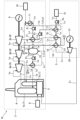
- FIG. 1 is a system configuration diagram of a combined power generation system according to an embodiment of the present invention.
- FIG. 11 is a system configuration diagram of a combined power generation system according to a modified example.
- 1 is a graph showing changes in specific enthalpy when the pressure of various gases is changed. This figure shows the assumptions regarding the thermodynamic properties of the heat source steam (exhaust steam) and the ammonia gas after vaporization used to estimate the exergy change.
- 1 is a graph showing the relationship between the exergy or power required to vaporize ammonia and the pressure of the vaporized ammonia.
- FIG. 1 is a diagram showing an outline of a simplified model of a thermal power generation facility common to Comparative Examples 1 and 2 and Examples 1 to 3.
- FIG. 1 is a diagram showing an overview of a simulation model of Comparative Example 1.
- FIG. 13 is a diagram showing an outline of a simulation model of Comparative Example 2.
- FIG. 1 is a diagram showing an overview of a simulation model of a first embodiment.
- FIG. 13 is a diagram showing an outline of a simulation model of a second embodiment.
- FIG. 13 is a diagram showing an outline of a simulation model of a third embodiment.
- 1 is a graph showing the amount of steam required to produce 1 ton of ammonia gas in each simulation model of Comparative Examples 1 and 2 and Examples 1 to 3.
- 1 is a graph showing the specific exergy of each fluid.
- 1 is a graph showing the estimated results of the total power generation amount in each simulation model of Comparative Examples 1 and 2 and Examples 1 to 3.
- 1 is a graph showing the estimated results of exergy balance per ton of ammonia gas in each simulation model of Comparative Examples 1 and 2 and Examples 1 to 3.
- FIG. 1 is a system configuration diagram of a combined power generation system according to this embodiment. As shown in FIG.
- the combined power generation system 1A includes a first power generation facility 2 that generates a first electric power by utilizing water vapor (hereinafter, simply referred to as "steam"), and a second power generation facility 3 that vaporizes liquid ammonia by utilizing residual heat of the steam generated in the first power generation facility 2 to generate the first electric power, and generates a second electric power by utilizing the vaporized ammonia gas, and is further characterized in that exhaust ammonia gas discharged from the second power generation facility 3 is combusted in a boiler facility 4 of the first power generation facility 2.
- steam water vapor
- the first power generation facility 2 in the combined power generation system 1A can be, for example, a conventional thermal power generation facility that can be directly converted. More specifically, the first power generation facility 2 in the combined power generation system 1A of this embodiment includes a boiler equipment 4 that generates steam, a steam turbine 8 (e.g., a high-pressure steam turbine 8a, an intermediate-pressure steam turbine 8b, and a low-pressure steam turbine 8c) driven by steam generated in the boiler equipment 4, and a first generator 9 connected to the steam turbine 8 to generate electricity.
- a steam turbine 8 e.g., a high-pressure steam turbine 8a, an intermediate-pressure steam turbine 8b, and a low-pressure steam turbine 8c
- the above-mentioned first power generation facility 2 further includes a steam supply pipe Lw (hereinafter simply referred to as "piping Lw ”) for supplying steam (heat medium) generated in the boiler equipment 4, pumps P1 to P3 as a power source for circulating the steam (heat medium) in this pipe Lw , heat exchangers 12 and 13 including a condenser 11, and related equipment or devices such as a deaerator 14 and water supply equipment 10, at desired locations on the pipe Lw .
- the deaerator 14 is a device for removing gases such as oxygen and carbon dioxide present in the heat medium (water) used to operate the steam turbine 8 .
- the second power generation facility 3 in the combined power generation system 1A includes a storage facility 15 for storing liquid ammonia, an ammonia vaporization facility 16 (energy addition facility) for vaporizing the liquid ammonia supplied from this storage facility 15 by utilizing residual heat of exhaust steam discharged from the steam turbine 8 in the first power generation facility 2, an ammonia turbine 20 driven by ammonia gas (superheated ammonia gas) which is the turbine driving fluid produced in this ammonia vaporization facility 16, and a second generator 21 connected to this ammonia turbine 20 for generating second electricity.
- ammonia liquid ammonia and ammonia gas
- La consisting of an independent pipe separate from the above-mentioned pipe Lw .
- the boiler facility 4 of the first power generation facility 2 includes a combustion unit 5. Furthermore, this combustion unit 5 is supplied with fuel (e.g., fossil fuels such as natural gas, coal, and oil, and combustible waste, etc.) from a fuel supply device 6, and is also supplied with exhaust ammonia gas discharged from the ammonia turbine 20 in the second power generation facility 3 as fuel.
- fuel e.g., fossil fuels such as natural gas, coal, and oil, and combustible waste, etc.
- fuel supply device 6 e.g., fossil fuels such as natural gas, coal, and oil, and combustible waste, etc.
- exhaust ammonia gas discharged from the ammonia turbine 20 in the second power generation facility 3 as fuel.
- the fuel supplied from the fuel supply device 6 and the exhaust ammonia gas discharged from the ammonia turbine 20 are mixed and burned, but the fuel supplied to the combustion section 5 may be only the exhaust ammonia gas.
- the power generation method (steam turbine method) of the first power generation facility 2 in the combined power generation system 1A does not have to be limited to the method combining the extraction condensation type and the reheat type shown in FIG. 1, but may be a method adopting any one of these types or any of the methods described below.
- (1) Back pressure type (2) Condensate type (3) Extraction back pressure type
- the exhaust ammonia gas discharged from the ammonia turbine 20 as fuel in the boiler equipment 4 of the first power generation facility 2, it is possible to reduce the amount of carbon dioxide emissions compared to the case where only fuel that emits carbon dioxide is burned in the boiler equipment 4.
- a part of the steam used to operate the steam turbine 8 is diverted as a heat medium for vaporizing the liquid ammonia. Therefore, in the combined power generation system 1A according to this embodiment, the thermal energy supplied to the steam turbine 8 is reduced, which reduces the amount of generated first electric power.
- the ammonia gas vaporized in the ammonia vaporization facility 16 of the second power generation facility 3 is further superheated, and the ammonia turbine 20 is operated using this superheated ammonia gas (turbine driving fluid) to generate second electricity.
- the combined power generation system 1A (or combined power generation method) of this embodiment part or all of the reduction in output of the first power at the first power generation facility 2 can be compensated for by the second power generation at the second power generation facility 3.
- the combined power generation system 1B according to the modified example shown in FIG. 2 the case where the optional facility 22 is one has been described as an example, but the exhaust ammonia gas discharged from the ammonia turbine 20 may be supplied as fuel to two or more optional facilities 22 depending on the scale of the first power generation facility 2 or the like (optional component).
- the combined power generation system 1B according to a modified example may supply exhaust ammonia gas discharged from the ammonia turbine 20 not only to at least one optional equipment 22 but also to the combustion section 5 in the boiler equipment 4 of the first power generation facility 2 (optional component).
- the combined power generation system 1B is specified as a method invention, it is a combined power generation method in which a steam turbine 8 connected to a first generator 9 is driven by steam generated in a boiler facility 4 to generate first electricity, ammonia gas, which is a turbine driving fluid, is generated from liquid ammonia using residual heat of exhaust steam from the steam turbine 8, an ammonia turbine 20 connected to a second generator 21 is driven by ammonia gas to generate second electricity, and exhaust ammonia gas discharged from the ammonia turbine 20 is combusted in the boiler facility 4 or at least one optional facility other than the boiler facility 4 (for example, optional facility 22).
- the combined power generation system 1B according to the above-mentioned modified example (or the combined power generation method according to the modified example) has the same effects as those of the combined power generation system 1A (or the combined power generation method) described in [1-2] above.
- the amount of carbon dioxide emitted from the boiler equipment 4 and/or the at least one optional piece of equipment 22 can be reduced compared to the case where only fuel that emits carbon dioxide is burned in the combustion section 5 of the boiler equipment 4 and/or the combustion section 23 of at least one optional piece of equipment 22.
- the exhaust ammonia gas may be supplied to the combustion section 5 of the boiler equipment 4 shown in FIG. 1 and FIG. 2 or the combustion section 23 of the optional equipment 22 shown in FIG. 2 by using the residual pressure of the exhaust ammonia gas discharged from the ammonia turbine 20 (optional component).
- a gas supply device such as a blower to supply the exhaust ammonia gas discharged from the ammonia turbine 20 to the combustion section 5 and the combustion section 23 .
- the liquid ammonia which is supplied from the storage facility 15 shown in Figures 1 and 2 and is the heat medium that runs the ammonia turbine 20, may contain up to 1 mass % water (optional component).
- the equipment constituting the ammonia feed line La and the ammonia vaporization facility 16 in the first power generation facility 2 is made of steel, it is possible to suppress the occurrence of stress corrosion cracking of the steel. As a result, it is possible to reduce the cost required for maintenance and repair of the second power generation facility 3. This makes it possible to reduce the cost required for generating the second electric power in the second power generation facility 3.
- ⁇ 3-2-2 Temperature of exhaust ammonia gas in the combustion section>
- liquid ammonia which is a heat medium for operating the ammonia turbine 20
- the temperature of the ammonia gas (exhaust ammonia gas) supplied to the combustion section 5 of the boiler equipment 4 shown in FIGS. 1 and 2 or the combustion section 23 of the optional equipment 22 shown in FIG. 2 may be set to 18.8° C. or higher (optional component).
- water in the ammonia gas (exhaust ammonia gas) from condensing under atmospheric pressure, thereby making it possible to suppress corrosion of the steel material constituting the ammonia feed line La (see FIG. 1 or FIG.
- the second power generation facility 3 may include a pressurizing facility P 4 (e.g., a pump) that pressurizes the liquid ammonia to be supplied to the ammonia vaporization facility 16 to 6 MPaG or more (optional component).
- a pressurizing facility P 4 e.g., a pump
- the thermal energy required to generate superheated ammonia gas can be reduced compared to the case of vaporizing and superheating unpressurized liquid ammonia.
- the amount of exhaust steam extracted from the steam turbine 8 of the first power generation facility 2 to vaporize and superheat ammonia in the second power generation facility 3 can be reduced. The reason for this is explained below.
- Figure 3 is a graph showing the change in specific enthalpy when the pressure of various gases is changed.
- the specific enthalpy of various gases shown in Figure 3 was estimated using "REFPROP Version 10" of the National Institute of Standards and Technology (NSIT).
- NIT National Institute of Standards and Technology
- the specific enthalpy of ammonia ( NH3 ), water ( H2O ), methanol, and ethanol tended to depend on pressure.
- the specific enthalpy of polar molecules such as ammonia has pressure dependence.
- the combined power generation system 1A according to this embodiment or the combined power generation system 1B according to the modified example by pressurizing liquid ammonia to a pressure close to the critical pressure when vaporizing it, it is possible to reduce the thermal energy required for vaporization, i.e., the amount of exhaust steam extracted from the first power generation facility 2, compared to the case of vaporizing unpressurized ammonia.
- liquid ammonia undergoes a smaller volume change when pressurized than ammonia gas, so the amount of power energy required to pressurize liquid ammonia is less than that required to pressurize ammonia gas.
- the total energy of the steam supplied to the inlet of a steam turbine (e.g., the steam turbine 8) in a thermal power generation facility is a combination of the above-mentioned (i) electrical energy and (ii) thermal energy, and is generally referred to as "enthalpy (H)."
- the enthalpy (H) is defined by the following (Equation 1).
- H enthalpy
- S entropy
- the exergy obtained from the thermal power generation facility (e.g., first power generation facility 2) or the like is the maximum work (electrical energy) that can be extracted from the energy of steam supplied to the inlet of the steam turbine (e.g., steam turbine 8) before this steam reaches an arbitrary reference environmental state.
- FIG. 4A is a diagram showing preconditions for the thermodynamic properties of steam (exhaust steam) as a heat source used in estimating the exergy change shown in FIG. 4B and ammonia gas after vaporization.
- FIG. 4B is a graph showing the relationship between the exergy or power required for vaporizing liquid ammonia and the pressure of the vaporized ammonia.
- the thermodynamic properties of the steam (exhaust steam) and ammonia shown in Fig. 4A were also estimated using "REFPROP Version 10" by the National Institute of Standards and Technology (NSIT). In the graph of FIG.
- “Curve 3" is the difference obtained by subtracting the value of "Line 1" and the value of “Curve 1” from the value of "Curve 2" at an arbitrary pressure value of vaporized ammonia (the value on the X-axis).
- this exergy balance (Curve 3) is, the more the total power generation amount of the first power generation facility 2 and the second power generation facility 3 increases compared to the power generation amount of a conventional thermal power generation facility (corresponding to only the first power generation facility 2).
- the exergy balance begins to increase less when the vaporized ammonia pressure (X-axis) exceeds 6 MPaG, and peaks at 16 MPaG.
- the volume of liquid ammonia changes less when pressurized than that of vaporized ammonia gas. Therefore, even if additional power energy (line 1) is required to drive the pressurizing equipment P4 in the second power generation facility 3 shown in FIG. 1 or 2, the increase in power energy has a small effect on the exergy balance (curve 3) described above (see FIG. 4B).
- ammonia which is a polar molecule
- the liquid ammonia supplied to the ammonia vaporization equipment 16 is pressurized to 6 MPaG or more, so that the total power generation amount of the first power generation facility 2 and the second power generation facility 3 can be made larger than the power generation amount of a conventional thermal power generation facility (corresponding to only the first power generation facility 2).
- the upper limit of the liquid ammonia pressure is desirably set to less than 11.2 MPaG, which is the critical pressure of ammonia.
- the steam turbine 8 in the first power generation facility 2 may include, for example, a high-pressure steam turbine 8a that discharges high-pressure exhaust steam, an intermediate-pressure steam turbine 8b that discharges intermediate-pressure exhaust steam having an outlet temperature of 200 to 450°C, and a low-pressure steam turbine 8c that discharges low-pressure exhaust steam having an outlet temperature of 30 to 200°C. Furthermore, as shown in FIGS.
- the ammonia vaporization equipment 16 in the second power generation facility 3 may include a preheater 17 (heat exchanger) that preheats the liquid ammonia supplied from the storage equipment 15, a vaporizer 18 (heat exchanger) that vaporizes the liquid ammonia preheated in the preheater 17, and a superheater 19 (heat exchanger) that superheats the ammonia gas vaporized in the vaporizer 18.
- a preheater 17 heat exchanger
- vaporizer 18 heat exchanger
- superheater 19 heat exchanger
- first power generation facility 2 and the second power generation facility 3 shown in Figure 1 or Figure 2 are configured as described above, they may be provided with a medium-pressure exhaust steam supply line L1 (the part indicated by a dashed line in piping Lw in Figures 1 and 2) that supplies a portion of the medium-pressure exhaust steam discharged from the medium-pressure steam turbine 8b of the first power generation facility 2 to the superheater 19 and supplies a portion of the medium-pressure exhaust steam cooled in the superheater 19 to the vaporizer 18 (optional component).
- L1 the medium-pressure exhaust steam supply line L1 (the part indicated by a dashed line in piping Lw in Figures 1 and 2) that supplies a portion of the medium-pressure exhaust steam discharged from the medium-pressure steam turbine 8b of the first power generation facility 2 to the superheater 19 and supplies a portion of the medium-pressure exhaust steam cooled in the superheater 19 to the vaporizer 18 (optional component).
- the liquid ammonia can be efficiently vaporized by utilizing the exhaust steam (medium pressure exhaust steam) supplied from the first power generation facility 2. More specifically, when comparing the latent heat of vaporization of superheated ammonia (ammonia gas) and that of low-pressure exhaust steam, the latent heat of vaporization of the low-pressure exhaust steam is significantly larger.
- Latent heat of vaporization of water vapor at 144 ° C: 2130 (kJ / kg) Therefore, by using the medium-pressure exhaust steam discharged from the medium-pressure steam turbine 8b of the first power generation facility 2 as the heat source used in the superheater 19 and vaporizer 18 of the ammonia vaporization equipment 16, ammonia can be efficiently vaporized and superheated using a small amount of medium-pressure exhaust steam. As a result, the output of the ammonia turbine 20 by the superheated ammonia gas can be increased.
- a hot water supply line L 2 (a portion indicated by a dashed dotted line in the piping L w in FIG. 1 and FIG. 2 ) may be provided to supply hot water (second hot water) generated from equipment related to the low-pressure steam turbine 8 c of the first power generation facility 2 to the preheater 17 of the ammonia vaporization facility 16 in the second power generation facility 3 (optional component).
- the second hot water in the hot water supply line L2 may be hot water after heat exchange generated in a condenser 11 (heat exchanger) and/or a heat exchanger 12 provided downstream of the low-pressure steam turbine 8c of the first power generation facility 2 shown in Fig. 1 or 2. More specifically, the second hot water may be, for example, feed water on the low-pressure steam turbine 8c side of the first power generation facility 2, a feed water heater drain, or the like.
- a line may be provided to supply hot water (first hot water) generated from the vaporizer 18 of the ammonia vaporization equipment 16 in the second power generation facility 3 or its related equipment to the preheater 17, and this line may be used as the hot water supply line L2 (not shown).
- the first hot water may be, for example, evaporator drain.
- the combined power generation system 1A according to this embodiment or the combined power generation system 1B according to the modified example includes a hot water supply line L2 in addition to the intermediate pressure exhaust steam supply line L1 , the exhaust heat discharged into the environment in the first power generation facility 2 can be effectively utilized for vaporizing (more specifically, preheating) the liquid ammonia.
- the first power generation facility 2 has one each of a high-pressure steam turbine 8a, an intermediate-pressure steam turbine 8b, and a low-pressure steam turbine 8c, but the first power generation facility 2 may have multiple each of the high-pressure steam turbine 8a, the intermediate-pressure steam turbine 8b, and the low-pressure steam turbine 8c (optional components).
- the first power generation facility 2 may include a plurality of ammonia turbines 20 as necessary (optional components). In either case, the same actions and effects as those of the combined power generation system 1A according to this embodiment or the combined power generation system 1B according to the modified example are achieved.
- the turbine driving fluid that drives the ammonia turbine 20 is ammonia gas (superheated ammonia gas) as an example.
- this turbine driving fluid may be a supercritical ammonia fluid (optional component).
- an energy addition equipment (not shown) is provided that heats (residual heat of exhaust steam) and pressurizes (power for a pump or the like) liquid ammonia to generate a supercritical fluid of ammonia.
- the supercritical ammonia fluid produced in the energy addition facility is vaporized in an ammonia turbine 20 .
- the pressure of the ammonia is desirably set to 11.2 to 16 MPaG, which is the critical pressure of ammonia, taking into account the exergy balance (see FIG. 4B).
- FIGS. ⁇ 4-1: Simulation settings, etc.> A simplified type thermal power generation facility corresponding to the first power generation facility 2 shown in FIG. 1 was used as a model (see FIG. 5 below, hereinafter also simply referred to as the "simplified model"), and the method of vaporizing liquid ammonia supplied to the combustion section 5 of the boiler facility 4 was set to the following five types (Comparative Examples 1 and 2 and Examples 1 to 3), and the exergy balance was simulated.
- FIG. 5 is a diagram showing an outline of a simplified model of a thermal power generation facility (corresponding to the first power generation facility 2 in FIG. 1 ) common to the following five cases (Comparative Examples 1 and 2 and Examples 1 to 3).
- FIG. 5 is a diagram showing an outline of a simplified model of a thermal power generation facility (corresponding to the first power generation facility 2 in FIG. 1 ) common to the following five cases (Comparative Examples 1 and 2 and Examples 1 to 3).
- FIG. 6 is a diagram showing an outline of the simulation model of Comparative Example 1.
- FIG. 7 is a diagram showing an outline of the simulation model of Comparative Example 2.
- FIG. 8 is a diagram showing an outline of the simulation model of Example 1.
- FIG. 9 is a diagram showing an outline of the simulation model of Example 2.
- FIG. 10 is a diagram showing an outline of the simulation model of Example 3. In each of the simulation models shown in Figs. 8 to 10, the destination of the exhaust ammonia gas discharged from the ammonia gas turbine (corresponding to the ammonia turbine 20 in Figs. 1 and 2) is simply displayed as "to the boiler".
- FIG. 11 is a graph showing the amount of steam required to produce 1 ton of ammonia gas in each of the simulation models of Comparative Examples 1 and 2 and Examples 1 to 3.
- the steam (thermal energy) used to operate the steam turbine is used to vaporize the liquid ammonia.
- a reduction in the output of the steam turbine is unavoidable.
- Fig. 12 is a graph showing the specific exergy of each fluid.
- Fig. 13 is a graph showing the estimated results of the total power generation amount in each simulation model of Comparative Examples 1 and 2 and Examples 1 to 3.
- the estimated values of the specific exergy of each fluid shown in Fig. 12 were used to estimate the total power generation amount for each simulation model shown in Fig. 13.
- the reference environment settings used to calculate the specific exergy of each fluid shown in Fig. 12 are shown in Table 2 below.
- the specific exergy of each fluid was estimated using "REFPROP Version 10" from the National Institute of Standards and Technology (NSIT) in the United States.
- superheated ammonia gas (pressurized superheated vaporized NH 3 ) has a specific exergy approximately equal to that of steam (300 kPaG steam) for operating an intermediate pressure (steam) turbine. Therefore, as shown in Figure 13, by operating an ammonia gas turbine ( NH3 turbine) with superheated ammonia gas (pressurized superheated vaporized NH3 ) generated using the residual heat of the steam (300 kPaG steam) for operating the medium-pressure (steam) turbine, it is possible to compensate for the output loss of the medium-pressure (steam) turbine in a simplified model of a thermal power plant.
- FIG. 14 is a graph showing the estimation results of the exergy balance per ton of ammonia gas in each of the simulation models of Comparative Examples 1 and 2 and Examples 1 to 3. As shown in FIG. 14, in Examples 1 to 3 in which the vaporized ammonia gas was further converted into superheated ammonia gas to operate the ammonia gas turbine, the exergy balance was positive.
- the combined power generation system 1A of this embodiment or the combined power generation system 1B of the modified example as well as the combined power generation system of the present invention in which the turbine driving fluid in the second power generation facility 3 is ammonia supercritical fluid, a large amount of ammonia gas for fuel can be produced while suppressing energy loss during vaporization.
- the present invention is a combined power generation system and method that can heat liquid ammonia to produce a large amount of ammonia gas for combustion, and that can suppress a decrease in the power output of a power generation facility even if thermal energy for power generation in the power generation facility is diverted, and can be used in technical fields related to combined facilities such as power generation facilities and chemical plants.
Landscapes
- Engineering & Computer Science (AREA)
- Chemical & Material Sciences (AREA)
- Combustion & Propulsion (AREA)
- Mechanical Engineering (AREA)
- General Engineering & Computer Science (AREA)
- Engine Equipment That Uses Special Cycles (AREA)
- Feeding And Controlling Fuel (AREA)
Abstract
Priority Applications (3)
| Application Number | Priority Date | Filing Date | Title |
|---|---|---|---|
| KR1020257043508A KR20260020966A (ko) | 2023-06-09 | 2024-05-14 | 복합 발전 시스템 및 복합 발전 방법 |
| CN202480038421.5A CN121311665A (zh) | 2023-06-09 | 2024-05-14 | 复合发电系统及复合发电方法 |
| AU2024284432A AU2024284432A1 (en) | 2023-06-09 | 2024-05-14 | Composite power generation system and composite power generation method |
Applications Claiming Priority (2)
| Application Number | Priority Date | Filing Date | Title |
|---|---|---|---|
| JP2023095697A JP2024176859A (ja) | 2023-06-09 | 2023-06-09 | 複合発電システム及び複合発電方法 |
| JP2023-095697 | 2023-06-09 |
Publications (1)
| Publication Number | Publication Date |
|---|---|
| WO2024252860A1 true WO2024252860A1 (fr) | 2024-12-12 |
Family
ID=93795245
Family Applications (1)
| Application Number | Title | Priority Date | Filing Date |
|---|---|---|---|
| PCT/JP2024/017731 Ceased WO2024252860A1 (fr) | 2023-06-09 | 2024-05-14 | Système et procédé de production d'énergie composite |
Country Status (5)
| Country | Link |
|---|---|
| JP (1) | JP2024176859A (fr) |
| KR (1) | KR20260020966A (fr) |
| CN (1) | CN121311665A (fr) |
| AU (1) | AU2024284432A1 (fr) |
| WO (1) | WO2024252860A1 (fr) |
Citations (6)
| Publication number | Priority date | Publication date | Assignee | Title |
|---|---|---|---|---|
| JP2002122006A (ja) * | 2000-10-14 | 2002-04-26 | Minoru Matsuo | 低温排熱を利用した発電設備 |
| JP2004124937A (ja) * | 2002-08-06 | 2004-04-22 | Tatsumi Akimine | 複合熱交換による複合発電法 |
| JP2018123756A (ja) * | 2017-01-31 | 2018-08-09 | 株式会社Ihi | 熱サイクル設備 |
| JP2018200029A (ja) * | 2017-05-29 | 2018-12-20 | 株式会社Ihi | 発電システム |
| JP2019203637A (ja) * | 2018-05-23 | 2019-11-28 | 株式会社Ihi | 蒸気発生設備 |
| JP2020148357A (ja) * | 2019-03-11 | 2020-09-17 | 株式会社Ihi | 発電システム |
Family Cites Families (1)
| Publication number | Priority date | Publication date | Assignee | Title |
|---|---|---|---|---|
| JP7455781B2 (ja) | 2021-07-12 | 2024-03-26 | 三菱重工業株式会社 | 発電プラント用のアンモニア供給ユニット、発電プラント用のアンモニア気化処理方法、及び発電プラント |
-
2023
- 2023-06-09 JP JP2023095697A patent/JP2024176859A/ja active Pending
-
2024
- 2024-05-14 WO PCT/JP2024/017731 patent/WO2024252860A1/fr not_active Ceased
- 2024-05-14 CN CN202480038421.5A patent/CN121311665A/zh active Pending
- 2024-05-14 AU AU2024284432A patent/AU2024284432A1/en active Pending
- 2024-05-14 KR KR1020257043508A patent/KR20260020966A/ko active Pending
Patent Citations (6)
| Publication number | Priority date | Publication date | Assignee | Title |
|---|---|---|---|---|
| JP2002122006A (ja) * | 2000-10-14 | 2002-04-26 | Minoru Matsuo | 低温排熱を利用した発電設備 |
| JP2004124937A (ja) * | 2002-08-06 | 2004-04-22 | Tatsumi Akimine | 複合熱交換による複合発電法 |
| JP2018123756A (ja) * | 2017-01-31 | 2018-08-09 | 株式会社Ihi | 熱サイクル設備 |
| JP2018200029A (ja) * | 2017-05-29 | 2018-12-20 | 株式会社Ihi | 発電システム |
| JP2019203637A (ja) * | 2018-05-23 | 2019-11-28 | 株式会社Ihi | 蒸気発生設備 |
| JP2020148357A (ja) * | 2019-03-11 | 2020-09-17 | 株式会社Ihi | 発電システム |
Also Published As
| Publication number | Publication date |
|---|---|
| JP2024176859A (ja) | 2024-12-19 |
| AU2024284432A1 (en) | 2025-11-06 |
| KR20260020966A (ko) | 2026-02-12 |
| CN121311665A (zh) | 2026-01-09 |
Similar Documents
| Publication | Publication Date | Title |
|---|---|---|
| JP7173245B2 (ja) | 発電システム | |
| TW449642B (en) | Method of heating gas turbine fuel in a combined cycle power plant using multi-component flow mixtures | |
| JP5567961B2 (ja) | 二重再熱ランキンサイクルシステム及びその方法 | |
| JP6245404B1 (ja) | 燃焼装置および発電設備 | |
| JP5062380B2 (ja) | 排熱回収システム及びエネルギ供給システム | |
| JP6819323B2 (ja) | 熱サイクル設備 | |
| MX2007010601A (es) | Caldera de combustible con oxigeno a base de modulos. | |
| JP6265535B2 (ja) | 給水予熱装置、これを備えているガスタービンプラント、及び給水予熱方法 | |
| JP3905967B2 (ja) | 発電・給湯システム | |
| KR102621628B1 (ko) | 복합 사이클 발전소용 이중 사이클 시스템 | |
| US20080011457A1 (en) | Method and apparatus for acquiring heat from multiple heat sources | |
| JP7121185B2 (ja) | 天然ガス再ガス化を含む発電プラント | |
| WO2024252860A1 (fr) | Système et procédé de production d'énergie composite | |
| CN102105656B (zh) | 混合发电装置 | |
| RU2561776C2 (ru) | Парогазовая установка | |
| JP4666641B2 (ja) | エネルギー供給システム、エネルギー供給方法、及びエネルギー供給システムの改造方法 | |
| RU2686541C1 (ru) | Парогазовая установка | |
| RU2561780C2 (ru) | Парогазовая установка | |
| JP6132616B2 (ja) | ガスタービンプラント、及びガスタービンプラントの運転方法 | |
| Korobitsyn | Enhancing direct-fired power plants performance by use of gas turbine technology | |
| JP2023067442A (ja) | 蒸気供給設備 | |
| JPH1136820A (ja) | 水素燃焼タービンプラント | |
| CN121844127A (zh) | 燃料气体加热装置及联合循环电站 | |
| UA54676A (uk) | Спосіб роботи парогазової енергетичної установки |
Legal Events
| Date | Code | Title | Description |
|---|---|---|---|
| 121 | Ep: the epo has been informed by wipo that ep was designated in this application |
Ref document number: 24819097 Country of ref document: EP Kind code of ref document: A1 |
|
| WWE | Wipo information: entry into national phase |
Ref document number: AU2024284432 Country of ref document: AU |
|
| WWE | Wipo information: entry into national phase |
Ref document number: 202517105541 Country of ref document: IN |
|
| ENP | Entry into the national phase |
Ref document number: 2024284432 Country of ref document: AU Date of ref document: 20240514 Kind code of ref document: A |
|
| WWP | Wipo information: published in national office |
Ref document number: 202517105541 Country of ref document: IN |
|
| ENP | Entry into the national phase |
Ref document number: 1020257043508 Country of ref document: KR Free format text: ST27 STATUS EVENT CODE: A-0-1-A10-A15-NAP-PA0105 (AS PROVIDED BY THE NATIONAL OFFICE) |