EP2423582A2 - Appareil de surveillance des tuyaux de transfert de chaleur - Google Patents
Appareil de surveillance des tuyaux de transfert de chaleur Download PDFInfo
- Publication number
- EP2423582A2 EP2423582A2 EP10151523A EP10151523A EP2423582A2 EP 2423582 A2 EP2423582 A2 EP 2423582A2 EP 10151523 A EP10151523 A EP 10151523A EP 10151523 A EP10151523 A EP 10151523A EP 2423582 A2 EP2423582 A2 EP 2423582A2
- Authority
- EP
- European Patent Office
- Prior art keywords
- transfer tube
- heat transfer
- differential pressure
- heat
- tube bundles
- Prior art date
- Legal status (The legal status is an assumption and is not a legal conclusion. Google has not performed a legal analysis and makes no representation as to the accuracy of the status listed.)
- Granted
Links
- 238000012546 transfer Methods 0.000 title claims abstract description 123
- 238000012544 monitoring process Methods 0.000 title claims abstract description 35
- UGFAIRIUMAVXCW-UHFFFAOYSA-N Carbon monoxide Chemical compound [O+]#[C-] UGFAIRIUMAVXCW-UHFFFAOYSA-N 0.000 claims abstract description 31
- 239000003546 flue gas Substances 0.000 claims abstract description 31
- 238000011144 upstream manufacturing Methods 0.000 claims abstract description 14
- 230000002159 abnormal effect Effects 0.000 abstract description 4
- 238000011084 recovery Methods 0.000 description 53
- OAKJQQAXSVQMHS-UHFFFAOYSA-N Hydrazine Chemical compound NN OAKJQQAXSVQMHS-UHFFFAOYSA-N 0.000 description 32
- 239000004071 soot Substances 0.000 description 29
- 239000007789 gas Substances 0.000 description 19
- MWUXSHHQAYIFBG-UHFFFAOYSA-N Nitric oxide Chemical compound O=[N] MWUXSHHQAYIFBG-UHFFFAOYSA-N 0.000 description 10
- 239000000428 dust Substances 0.000 description 9
- 238000005259 measurement Methods 0.000 description 7
- 238000007664 blowing Methods 0.000 description 6
- 238000000034 method Methods 0.000 description 6
- 238000006243 chemical reaction Methods 0.000 description 5
- 230000003009 desulfurizing effect Effects 0.000 description 4
- 238000000605 extraction Methods 0.000 description 4
- XLYOFNOQVPJJNP-UHFFFAOYSA-N water Substances O XLYOFNOQVPJJNP-UHFFFAOYSA-N 0.000 description 4
- QGZKDVFQNNGYKY-UHFFFAOYSA-N Ammonia Chemical compound N QGZKDVFQNNGYKY-UHFFFAOYSA-N 0.000 description 3
- 238000001514 detection method Methods 0.000 description 3
- 239000012716 precipitator Substances 0.000 description 3
- 238000003303 reheating Methods 0.000 description 3
- 239000007921 spray Substances 0.000 description 3
- 229910052815 sulfur oxide Inorganic materials 0.000 description 3
- 238000012360 testing method Methods 0.000 description 3
- IJGRMHOSHXDMSA-UHFFFAOYSA-N Atomic nitrogen Chemical compound N#N IJGRMHOSHXDMSA-UHFFFAOYSA-N 0.000 description 2
- 229910000831 Steel Inorganic materials 0.000 description 2
- 238000002485 combustion reaction Methods 0.000 description 2
- 239000000446 fuel Substances 0.000 description 2
- 239000007788 liquid Substances 0.000 description 2
- 239000010959 steel Substances 0.000 description 2
- 235000019738 Limestone Nutrition 0.000 description 1
- 239000000809 air pollutant Substances 0.000 description 1
- 231100001243 air pollutant Toxicity 0.000 description 1
- 229910021529 ammonia Inorganic materials 0.000 description 1
- -1 and consequently Substances 0.000 description 1
- 230000015572 biosynthetic process Effects 0.000 description 1
- 239000006227 byproduct Substances 0.000 description 1
- 238000004364 calculation method Methods 0.000 description 1
- 239000003054 catalyst Substances 0.000 description 1
- 239000003638 chemical reducing agent Substances 0.000 description 1
- 239000003245 coal Substances 0.000 description 1
- 239000000567 combustion gas Substances 0.000 description 1
- 238000004590 computer program Methods 0.000 description 1
- 230000008021 deposition Effects 0.000 description 1
- 230000000694 effects Effects 0.000 description 1
- 230000006870 function Effects 0.000 description 1
- 239000010440 gypsum Substances 0.000 description 1
- 229910052602 gypsum Inorganic materials 0.000 description 1
- 239000006028 limestone Substances 0.000 description 1
- 239000000203 mixture Substances 0.000 description 1
- 238000012986 modification Methods 0.000 description 1
- 230000004048 modification Effects 0.000 description 1
- 229910052757 nitrogen Inorganic materials 0.000 description 1
- 230000000737 periodic effect Effects 0.000 description 1
- 238000010926 purge Methods 0.000 description 1
- 238000005070 sampling Methods 0.000 description 1
- 239000000779 smoke Substances 0.000 description 1
- 230000003068 static effect Effects 0.000 description 1
- XTQHKBHJIVJGKJ-UHFFFAOYSA-N sulfur monoxide Chemical class S=O XTQHKBHJIVJGKJ-UHFFFAOYSA-N 0.000 description 1
- 239000002699 waste material Substances 0.000 description 1
Images


Classifications
-
- G—PHYSICS
- G01—MEASURING; TESTING
- G01M—TESTING STATIC OR DYNAMIC BALANCE OF MACHINES OR STRUCTURES; TESTING OF STRUCTURES OR APPARATUS, NOT OTHERWISE PROVIDED FOR
- G01M3/00—Investigating fluid-tightness of structures
- G01M3/02—Investigating fluid-tightness of structures by using fluid or vacuum
- G01M3/04—Investigating fluid-tightness of structures by using fluid or vacuum by detecting the presence of fluid at the leakage point
- G01M3/20—Investigating fluid-tightness of structures by using fluid or vacuum by detecting the presence of fluid at the leakage point using special tracer materials, e.g. dye, fluorescent material, radioactive material
- G01M3/22—Investigating fluid-tightness of structures by using fluid or vacuum by detecting the presence of fluid at the leakage point using special tracer materials, e.g. dye, fluorescent material, radioactive material for pipes, cables or tubes; for pipe joints or seals; for valves; for welds; for containers, e.g. radiators
- G01M3/226—Investigating fluid-tightness of structures by using fluid or vacuum by detecting the presence of fluid at the leakage point using special tracer materials, e.g. dye, fluorescent material, radioactive material for pipes, cables or tubes; for pipe joints or seals; for valves; for welds; for containers, e.g. radiators for containers, e.g. radiators
- G01M3/228—Investigating fluid-tightness of structures by using fluid or vacuum by detecting the presence of fluid at the leakage point using special tracer materials, e.g. dye, fluorescent material, radioactive material for pipes, cables or tubes; for pipe joints or seals; for valves; for welds; for containers, e.g. radiators for containers, e.g. radiators for radiators
-
- F—MECHANICAL ENGINEERING; LIGHTING; HEATING; WEAPONS; BLASTING
- F22—STEAM GENERATION
- F22B—METHODS OF STEAM GENERATION; STEAM BOILERS
- F22B35/00—Control systems for steam boilers
- F22B35/007—Control systems for waste heat boilers
-
- F—MECHANICAL ENGINEERING; LIGHTING; HEATING; WEAPONS; BLASTING
- F22—STEAM GENERATION
- F22B—METHODS OF STEAM GENERATION; STEAM BOILERS
- F22B37/00—Component parts or details of steam boilers
- F22B37/02—Component parts or details of steam boilers applicable to more than one kind or type of steam boiler
- F22B37/10—Water tubes; Accessories therefor
-
- F—MECHANICAL ENGINEERING; LIGHTING; HEATING; WEAPONS; BLASTING
- F23—COMBUSTION APPARATUS; COMBUSTION PROCESSES
- F23J—REMOVAL OR TREATMENT OF COMBUSTION PRODUCTS OR COMBUSTION RESIDUES; FLUES
- F23J3/00—Removing solid residues from passages or chambers beyond the fire, e.g. from flues by soot blowers
-
- F—MECHANICAL ENGINEERING; LIGHTING; HEATING; WEAPONS; BLASTING
- F23—COMBUSTION APPARATUS; COMBUSTION PROCESSES
- F23L—SUPPLYING AIR OR NON-COMBUSTIBLE LIQUIDS OR GASES TO COMBUSTION APPARATUS IN GENERAL ; VALVES OR DAMPERS SPECIALLY ADAPTED FOR CONTROLLING AIR SUPPLY OR DRAUGHT IN COMBUSTION APPARATUS; INDUCING DRAUGHT IN COMBUSTION APPARATUS; TOPS FOR CHIMNEYS OR VENTILATING SHAFTS; TERMINALS FOR FLUES
- F23L15/00—Heating of air supplied for combustion
- F23L15/04—Arrangements of recuperators
-
- F—MECHANICAL ENGINEERING; LIGHTING; HEATING; WEAPONS; BLASTING
- F23—COMBUSTION APPARATUS; COMBUSTION PROCESSES
- F23N—REGULATING OR CONTROLLING COMBUSTION
- F23N5/00—Systems for controlling combustion
- F23N5/24—Preventing development of abnormal or undesired conditions, i.e. safety arrangements
- F23N5/242—Preventing development of abnormal or undesired conditions, i.e. safety arrangements using electronic means
-
- F—MECHANICAL ENGINEERING; LIGHTING; HEATING; WEAPONS; BLASTING
- F28—HEAT EXCHANGE IN GENERAL
- F28F—DETAILS OF HEAT-EXCHANGE AND HEAT-TRANSFER APPARATUS, OF GENERAL APPLICATION
- F28F27/00—Control arrangements or safety devices specially adapted for heat-exchange or heat-transfer apparatus
-
- F—MECHANICAL ENGINEERING; LIGHTING; HEATING; WEAPONS; BLASTING
- F28—HEAT EXCHANGE IN GENERAL
- F28G—CLEANING OF INTERNAL OR EXTERNAL SURFACES OF HEAT-EXCHANGE OR HEAT-TRANSFER CONDUITS, e.g. WATER TUBES OR BOILERS
- F28G15/00—Details
-
- F—MECHANICAL ENGINEERING; LIGHTING; HEATING; WEAPONS; BLASTING
- F28—HEAT EXCHANGE IN GENERAL
- F28G—CLEANING OF INTERNAL OR EXTERNAL SURFACES OF HEAT-EXCHANGE OR HEAT-TRANSFER CONDUITS, e.g. WATER TUBES OR BOILERS
- F28G15/00—Details
- F28G15/003—Control arrangements
-
- F—MECHANICAL ENGINEERING; LIGHTING; HEATING; WEAPONS; BLASTING
- F23—COMBUSTION APPARATUS; COMBUSTION PROCESSES
- F23N—REGULATING OR CONTROLLING COMBUSTION
- F23N2231/00—Fail safe
- F23N2231/26—Fail safe for clogging air inlet
-
- F—MECHANICAL ENGINEERING; LIGHTING; HEATING; WEAPONS; BLASTING
- F28—HEAT EXCHANGE IN GENERAL
- F28F—DETAILS OF HEAT-EXCHANGE AND HEAT-TRANSFER APPARATUS, OF GENERAL APPLICATION
- F28F2200/00—Prediction; Simulation; Testing
-
- Y—GENERAL TAGGING OF NEW TECHNOLOGICAL DEVELOPMENTS; GENERAL TAGGING OF CROSS-SECTIONAL TECHNOLOGIES SPANNING OVER SEVERAL SECTIONS OF THE IPC; TECHNICAL SUBJECTS COVERED BY FORMER USPC CROSS-REFERENCE ART COLLECTIONS [XRACs] AND DIGESTS
- Y02—TECHNOLOGIES OR APPLICATIONS FOR MITIGATION OR ADAPTATION AGAINST CLIMATE CHANGE
- Y02E—REDUCTION OF GREENHOUSE GAS [GHG] EMISSIONS, RELATED TO ENERGY GENERATION, TRANSMISSION OR DISTRIBUTION
- Y02E20/00—Combustion technologies with mitigation potential
- Y02E20/34—Indirect CO2mitigation, i.e. by acting on non CO2directly related matters of the process, e.g. pre-heating or heat recovery
Definitions
- the present invention relates to a heat transfer tube monitoring apparatus, for use in a heat exchanger such as a heat recovery apparatus, that monitors the state (e.g., scale formation, break) of a heat transfer tube bundle made of a fin tube or the like.
- the combustion gas generated by combusting fuel in a furnace 100 is made into flue gas by being heat exchanged for a required amount.
- the flue gas is discharged outside of the system through an air preheater (heat exchanger) 103 after nitrogen oxide contained in the flue gas is reduced with a denitrating apparatus 102 provided at a flue gas duct 101. Meanwhile, air is brought from the atmosphere, is heated by heat exchanged with the flue gas in the air preheater 103, and is supplied to the furnace 100 as the air for use in combustion.
- air preheater heat exchanger
- H1-114613 discloses an AH pressure difference monitoring unit 104 that is used for detecting the pressure difference between the entrance and the exit of the air preheater 103 and displays the detected difference thereon. Accordingly, the AH pressure difference monitoring unit 103 manages the operation performed by the air preheater 103.
- Deposition of dust in heat transfer tubes of a boiler in an exhaust heat recovery boiler (heat exchanger) provided in a steel furnace is automatically detected at an early stage without fail. Concentrated adherence of dust is prevented by preventing drain water from being sprayed to the boiler heat transfer tubes at a start of soot blower operation, thereby constantly maintaining draft strength in a furnace stack and the like.
- the soot blowers are started when a flue gas pressure drop ⁇ P (a pressure difference between the entrance and the exit) in the exhaust heat recovery boiler measured with a pressure difference meter becomes equal to or more than a set value, to surely prevent drop of heat transfer efficiency and exhaust heat recovery efficiency to the steel member.
- ⁇ P a pressure difference between the entrance and the exit
- 10-274408 discloses a method that, at a start of soot blower operation, sprays steam of the soot blowers in a direction in which no steam is to be sprayed toward the boiler heat transfer tube for a certain period of time to purge water inside soot blower tubes and pipes and then sprays steam toward the boiler heat transfer tube.
- the heat exchanger operation is controlled by detecting the pressure difference between the entrance and the exit of the heat exchanger.
- This arrangement causes a problem in that, when the heat exchanger is made by assembling a plurality of stages of heat transfer tube bundles, on which heat transfer tube bundle in the heat exchanger closure has occurred or dust has been deposited cannot be determined during the heat exchanger operation.
- An object of the present invention is to provide a heat transfer tube monitoring apparatus that is used for detecting a pressure difference of each of the heat transfer tube bundles during the heat exchanger operation constituted by a plurality of states of heat transfer tube bundles.
- the heat transfer tube monitoring apparatus thus enables identification of the status of scale having formed in each of the heat transfer tube bundles.
- Another object of the present invention is to specify an abnormal heat transfer tube bundle during the operation.
- a heat transfer tube monitoring apparatus for use in a heat exchanger including multiple-stage heat transfer tube bundles spaced apart from each other in a flow direction of flue gas, the heat transfer tube monitoring apparatus includes a differential pressure detecting unit that is used for detecting a differential pressure between upstream and downstream for each of the heat transfer tube bundles.
- the heat transfer tube monitoring apparatus further includes a heat-transfer medium detecting unit that is provided downstream of each of the heat transfer tube bundles and detects leakage of a heat-transfer medium flowing in the heat transfer tube bundles.
- the heat transfer tube monitoring apparatus further includes a display that displays thereon the differential pressure for each of the heat transfer tube bundles detected by the differential pressure detecting unit and presence of leakage of the heat-transfer medium detected by the heat-transfer medium detecting unit.
- An abnormal heat transfer tube bundle can be specified by detecting the pressure difference between the upstream and the downstream for each of the heat transfer tube bundles by the differential pressure detecting unit.
- the heat-transfer medium detecting unit detects the leakage of the heat-transfer medium, thereby confirming whether abnormal conditions, such as breaking down, have occurred on the heat transfer tube bundles.
- Figs. 1 and 2 the whole configuration of a thermal plant to which a heat transfer tube monitoring apparatus according to an embodiment of the present invention is applied will be outlined. Because coal or oil, for example, is used as fuel for a boiler 1, flue gas output from the boiler 1 contains nitrogen oxides (NO X ), sulfur oxides (SO X ), dust, and other air pollutants.
- NO X nitrogen oxides
- SO X sulfur oxides
- flue gas output from the boiler 1 is guided to a denitrating apparatus 2 filled with catalysts.
- NO X contained in the flue gas is reduced to water and nitrogen and detoxified with ammonia (NH 3 ) injected as a reducing agent.
- the temperature of high-temperature flue gas output from the denitrating apparatus 2 typically ranges from 120 to 150 degrees Celsius.
- the high-temperature flue gas is guided into heat recovery units 3 (a first heat recovery unit 3a and a second heat recovery unit 3b) where the gas is subjected to heat exchange with a heat-transfer medium (made of water and a deoxidant (e.g., hydrazine)) to recover the heat of the gas.
- a heat-transfer medium made of water and a deoxidant (e.g., hydrazine)
- the temperature of flue gas output from the heat recovery units 3a and 3b typically ranges from 80 to 110 degrees Celsius.
- the heat-transfer medium heated in the heat recovery units 3a and 3b is delivered to a reheating apparatus 6, which will be described later, through a heat-transfer medium circulation pipe 8.
- a soot blowing apparatus 9 is provided as illustrated in Fig. 2 .
- Low-temperature flue gas output from the first heat recovery unit 3a and the second heat recovery unit 3b is merged and guided into an electrical precipitator 4 where dust contained in the low-temperature flue gas is reduced.
- the dust-reduced flue gas is then guided into a desulfurizing apparatus 5 by an air blower (an ID fan) 10 driven by a motor.
- SO X contained in the flue gas is absorbed and reduced with limestone, and consequently, gypsum is produced as a by-product.
- the temperature of flue gas output from the desulfurizing apparatus 5 is typically lowered to a range from 45 to 55 degrees Celsius.
- This flue gas discharged to the atmosphere without any treatment is difficult to diffuse therein because of its low temperature, and may cause white smoke or other problems.
- the flue gas is guided into the reheating apparatus 6 where the gas is heated up to equal to or more than a certain temperature with the heat-transfer medium delivered from the heat recovery units 3a and 3b through the heat-transfer medium circulation pipe 8. Subsequently, the gas is discharged through a stack 7.
- Fig. 1 is an example of the boiler 1, the present invention is not limited thereto.
- flue gas sources such as internal combustion engines, gas turbines, and incinerators are also applicable.
- thermal plant thermal power plants and waste and other incineration plants are applicable.
- the heat recovery units 3a and 3b as heat exchangers will now be described in greater detail with reference to Fig. 2 .
- the two heat recovery units 3a and 3b each formed like a duct having a quadrangular cross section are provided in parallel to each other.
- the flue gas output from the denitrating apparatus 2 illustrated in Fig. 1 is diverged and guided into the first heat recovery unit 3a and the second heat recovery unit 3b.
- the first heat recovery unit 3a and the second heat recovery unit 3b include three-stage (multiple-stage) heat transfer tube bundles spaced apart from each other, i.e., high-temperature heat transfer tube bundles 11a and 11b, medium-temperature heat transfer tube bundles 12a and 12b, and low-temperature heat transfer tube bundles 13a and 13b, respectively, in the flow direction of flue gas.
- Each of the heat transfer tube bundles 11a to 13b is made of a fin tube folded in multiple stages to be arranged in a plurality of rows. Both ends of each fin tube are coupled to headers fixed to wall surfaces of the first heat recovery unit 3a and the second heat recovery unit 3b.
- Each header is coupled to the heat-transfer medium circulation pipe 8.
- a pressure detector P1 used for detecting the static pressure of flue gas is provided on the upstream of the high-temperature heat transfer tube bundles 11a and 11b above (on the ceilings or above side walls of) the first heat recovery unit 3a and the second heat recovery unit 3b, respectively.
- a second pressure detector P2 is provided between the high-temperature heat transfer tube bundles 11a and 11b and the medium-temperature heat transfer tube bundles 12a and 12b above the heat recovery units 3a and 3b, respectively.
- a third pressure detector P3 is provided between the medium-temperature heat transfer tube bundles 12a and 12b and the low-temperature heat transfer tube bundles 13a and 13b above the heat recovery units 3a and 3b, respectively.
- a fourth pressure detector P4 is provided on the downstream of the low-temperature heat transfer tube bundles 13a and 13b above the heat recovery units 3a and 3b, respectively. Furthermore, a gas flow meter F used for detecting the amount of flue gas is provided on the upstream of the high-temperature heat transfer tube bundles 11a and 11b above the heat recovery units 3a and 3b, respectively.
- the gas flow meter F is not limited to this example, and may be provided on the downstream of the low-temperature heat transfer tube bundles 13a and 13b instead.
- the soot blowing apparatus 9 including six soot blowers 14a, 14b, 15a, 15b, 16a, and 16b is provided.
- Each of the soot blowers 14a, 14b, 15a, 15b, 16a, and 16b is made of a soot blowing unit each having a plurality of cleansing liquid outlets (e.g., four cleansing liquid outlets) as illustrated in Figs. 3 and 4 .
- a first set of three soot blowers 14a, 15a, and 16a is driven for soot blower operation by a driving apparatus (not shown) to penetrate a side wall of the heat recovery unit 3a, enter the heat recovery unit 3a, and blow out ash, scale, or the like deposited in the high-temperature heat transfer tube bundle 11a, the medium-temperature heat transfer tube bundle 12a, and the low-temperature heat transfer tube bundle 13a, which are on the downstream of the respective blowers.
- a second set of three soot blowers 14b, 15b, and 16b is driven for soot blower operation by a driving apparatus (not shown) to penetrate a side wall of the heat recovery unit 3b, enter the heat recovery unit 3b, and blow out ash, scale, or the like deposited in the high-temperature heat transfer tube bundle 11b, the medium-temperature heat transfer tube bundle 12b, and the low-temperature heat transfer tube bundle 13b, which are on the downstream of the respective blowers.
- the high-temperature heat transfer tube bundle 11a, the medium-temperature heat transfer tube bundle 12a, and the low-temperature heat transfer tube bundle 13a of the first heat recovery unit 3a are arranged out of alignment in the flow direction of flue gas with the high-temperature heat transfer tube bundle 11b, the medium-temperature heat transfer tube bundle 12b, and the low-temperature heat transfer tube bundle 13b of the second heat recovery unit 3b.
- the first soot blowers 14a, 15a, and 16 and the second soot blowers 14b, 15b, and 16b are arranged in an alternating manner.
- a monitoring console 20 will now be described with reference to Fig. 3 .
- the following description is about the monitoring console 20 for the first heat recovery unit 3a.
- the monitoring console 20 for the second heat recovery unit 3b has a similar calculator, storage, and the like to those described below.
- the monitoring console 20 is in the form of a computer.
- the calculator, storage, and the like described below are in the form of a computer program, a sequence block, or a memory to execute respective functions.
- the computer may be a stand-alone small-scale computer or a central computer that controls and monitors the thermal plant.
- the pressure detectors P1 to P4 are used to measure pressures (Pt1 to Pt4) at the predetermined positions mentioned above in the first heat recovery unit 3a.
- the measured pressures Pt1 to Pt4 are sent to a differential pressure calculator 21 included in the monitoring console 20.
- the differential pressures ⁇ Pt1, ⁇ Pt2, and ⁇ Pt3 thus calculated are sent to a corrector 22 included in the monitoring console 20.
- a differential pressure detecting unit includes the pressure detectors P1 to P4 and the differential pressure calculator 21.
- a differential pressure detector DP1 serving as a differential pressure detecting unit used for detecting a differential pressure between the upstream and the downstream of the high-temperature heat transfer tube bundles 11
- a differential pressure detector DP2 serving as a differential pressure detecting unit used for detecting a differential pressure between the upstream and the downstream of the medium-temperature heat transfer tube bundles 12
- a differential pressure detector DP3 serving as a differential pressure detecting unit used for detecting a differential pressure between the upstream and the downstream of the low-temperature heat transfer tube bundles 13
- the differential pressure detectors DP1 to DP3 directly measure the differential pressures ⁇ Pt1, ⁇ Pt2, and ⁇ Pt3, respectively.
- the differential pressures ⁇ Pt1, ⁇ Pt2, and ⁇ Pt3 thus measured are sent directly to the corrector 22.
- a differential pressure detector DP0 used for detecting a differential pressure between the upstream of the high-temperature heat transfer tube bundles 11 and the downstream of the low-temperature heat transfer tube bundles 13 may be provided.
- the gas flow meter F is used to measure the amount of gas flowing in the first heat recovery unit 3a.
- the amount of gas thus measured is sent as an operation state amount Ft to the corrector 22.
- power consumed by the motor driving the air blower 10 may be set as the operation state amount Ft.
- the pitch angle of a fan included in the air blower may be set as the operation state amount Ft.
- a differential pressure between the inlet and the outlet of the air blower 10 may be set as the operation state amount Ft.
- the operation state amount Ft is sent to the corrector 22 from a control board, for example, of the motor driving the air blower 10.
- a rated operation state amount Fo is set in advance with the corrector 22.
- the amount of gas at the rated operation is set as the rated operation state amount Fo.
- the pitch angle at the rated operation is set as the rated operation state amount Fo.
- a differential pressure between the inlet and the outlet of the air blower 10 is set as the operation state amount Ft
- a differential pressure between the inlet and the outlet at the rated operation is set as the rated operation state amount Fo.
- the rated operation state amount Fo may be obtained from a data controller 23, which will be described later.
- a 100% load test may be conducted at a trial operation or an operational start of the thermal plant, and data measured in the test may be used as the rated operation state amount Fo.
- a conversion coefficient ⁇ for the rated operation means a conversion coefficient ⁇ for converting the differential pressures ⁇ Pt1, ⁇ Pt2, and ⁇ Pt3 measured based on the operation state amount Ft into the corresponding pressures with the rated amount of gas supplied.
- the conversion coefficient ⁇ is used for multiplication to obtain a differential pressure when the rated amount of gas is supplied to the high-temperature heat transfer tube bundles 11.
- the differential pressures ⁇ Pt1, ⁇ Pt2, and ⁇ Pt3, the corrected differential pressures ⁇ Pt1x, ⁇ Pt2x, and ⁇ Pt3x, and the operation state amount Ft are sent to the data controller 23 included in the monitoring console 20.
- the heat recovery unit 3a also includes a leakage detecting apparatus illustrated in Fig. 5 .
- baffles (effluent recovery plates) 30 are provided to the inner surface of the bottom plate of the heat recovery unit 3a on the upstream of the high-temperature heat transfer tube bundle 11a, on the upstream of the medium-temperature heat transfer tube bundle 12a, and on the upstream and the downstream of the low-temperature heat transfer tube bundle 13a.
- Each of the baffles (effluent recovery plates) 30 is substantially L-shaped and its center is placed downstream to readily converge therein effluent.
- An effluent recovery tube 31 is provided on the upstream of the center of each baffle 30, thereby recovering a heat-transfer medium that has leaked from the heat transfer tube bundle 11a, the medium-temperature heat transfer tube bundle 12a, and the low-temperature heat transfer tube bundle 13a.
- a midpoint of each effluent recovery tube 31 has a stop valve 32.
- the downstream end of each effluent recovery tube 31 is coupled to an effluent container 33 (effluent tank).
- each effluent container 33 is coupled to an effluent extraction tube (sampling tube) 34 for extracting effluent into an effluent component analyzer 36.
- Each effluent extraction tube 34 has a remote control valve 35 interposed therein.
- the effluent component analyzer 36 operates to open or close the remote control valves 35 sequentially on a periodic basis or based on measurement request signals sent from the monitoring console 20, and detects any one of: through which point (which effluent recovery tube 31) a deoxidant (e.g., hydrazine) is mixed, and the concentration of the deoxidant (e.g., hydrazine), or both.
- a deoxidant e.g., hydrazine
- concentration of the deoxidant e.g., hydrazine
- the results i.e., any one of: the presence of a deoxidant (e.g., hydrazine) detected for each effluent recovery tube 31, and the concentration of the deoxidant (e.g., hydrazine), or both) are sent to the data controller 23 included in the monitoring console 20.
- One effluent component analyzer 36 may be provided for each effluent extraction tube 34.
- the data controller 23 receives various types of data from the corrector 22, as described above, i.e., the differential pressures ⁇ Pt1, ⁇ Pt2, and ⁇ Pt3, the corrected differential pressures ⁇ Pt1x, ⁇ Pt2x, and ⁇ Pt3x, and the operation state amount Ft.
- the data controller 23 also receives, as described above, any one of: the presence of a deoxidant (e.g., hydrazine) detected for each effluent recovery tube 31, and the concentration of hydrazine, or both from the effluent component analyzer 36.
- a deoxidant e.g., hydrazine
- the data controller 23 receives event data IVTt indicating the measurement status of the various types of data (e.g., data measured at an operational start, shortly before soot blower operation, or shortly after soot blower operation; or data measured to be used as reference data) from an input apparatus (not shown) as required.
- event data IVTt indicating the measurement status of the various types of data (e.g., data measured at an operational start, shortly before soot blower operation, or shortly after soot blower operation; or data measured to be used as reference data) from an input apparatus (not shown) as required.
- the event data IVTt that serves as reference data is preferably adopted from data measured in a 100% load test conducted at a trial operation or an operational start of the thermal plant.
- year, month, and time data (measurement time t) indicating when measurement was conducted is obtained from a built-in clock in the computer.
- the data controller 23 sends data groups each made up of the measurement time t, the event data IVTt, the differential pressures ⁇ Pt1, ⁇ Pt2, and ⁇ Pt3, the corrected differential pressures ⁇ Pt1x, ⁇ Pt2x, and ⁇ Pt3x, the operation state amount Ft, the rated operation state amount Fo, and any one of: the presence of hydrazine detected for each effluent recovery tube 31, and the concentration of hydrazine, or both to a storage 24 included in the monitoring console 20.
- the storage 24 stores therein the data groups thus sent thereto in chronological order.
- a display 25 reads out necessary data from the storage 24, converts the data into image data by a known method, and displays the resultant data thereon.
- a plurality of images is displayed in an overlapping manner by a known method.
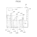
- a text display image La1 on the upper left on the display 25 indicates the operation state amount Ft and the rated operation state amount Fo together with corresponding names and units. If the amount of gas is adopted as the operation state amount Ft, the display indicates "Flue gas amount: 1000 m 3 /h; Rated gas amount: 1200 km 3 /h", for example.
- Text display images La2, La3, and La4 placed above bar charts described later indicate the presence of a deoxidant (e.g., hydrazine) detected.
- a deoxidant e.g., hydrazine
- the display indicates "Concentration of hydrazine leaked: 0 mmg", "Concentration of hydrazine leaked: 5 mmg” or "No hydrazine leaked", "Hydrazine leaked”.
- At least one line display image (two images Lb1 and Lb2 in the example illustrated in Fig. 6 ) is also displayed across the screen horizontally.
- the line display image Lb1 represents a reference (or default) line.
- the line display image Lb2 represents a tolerance line of pressure drops for each bundle, and is displayed in a range of Lb1 multiplied by 1.2 to 1.4, for example.
- the measured differential pressure display image Lc11 indicates the corrected differential pressure ⁇ Pt1x shortly before the latest soot blower operation
- the measured differential pressure display image Lc12 indicates the corrected differential pressure ⁇ Pt1x shortly after the latest soot blower operation
- the measured differential pressure display image Lc13 indicates the current corrected differential pressure ⁇ Pt1x.
- the measured differential pressure display images Lc11, Lc12, and Lc13 are bar charts with the differential pressure ⁇ Pt1 included in the data group stored as the "reference data" in the event data IVTt serving as the reference (or the default). This example indicates that scale or ash has formed or been deposited incrementally as time passes in the high-temperature heat transfer tube bundles 11 despite soot blower operation.
- the measured differential pressure display images Lc21, Lc22, and Lc23 represent an example of display at a predetermined time interval (e.g., every three months). Specifically, the measured differential pressure display image Lc21 indicates the corrected differential pressure ⁇ Pt2x obtained six months ago, the measured differential pressure display image Lc22 indicates the corrected differential pressure ⁇ Pt2x obtained three months ago, and the measured differential pressure display image Lc23 indicates the current corrected differential pressure ⁇ Pt2x. This example indicates that scale or ash has formed or been deposited incrementally as time passes in the medium-temperature heat transfer tube bundle 12a.
- the measured differential pressure display images Lc31, Lc32, and Lc33 represent an example of display at a predetermined time interval (e.g., every three months) like the measured differential pressure display images Lc21, Lc22, and Lc23.
- the measured differential pressure display image Lc31 indicates the corrected differential pressure ⁇ Pt3x obtained six months ago
- the measured differential pressure display image Lc22 indicates the corrected differential pressure ⁇ Pt3x obtained three months ago
- the measured differential pressure display image Lc33 indicates the current corrected differential pressure ⁇ Pt3x.
- This example indicates that no scale or ash has formed or been deposited in the low-temperature heat transfer tube bundles 13.
- the example illustrated in Fig. 3 may be modified as follows: the data controller 23 sends data groups each made up of the measurement time t, the event data IVTt, the measured pressures Pt1 to Pt4 measured by the pressure detectors P1 to P4, respectively, the operation state amount Ft, the rated operation state amount Fo, and any one of: the presence of hydrazine detected for each effluent recovery tube 31, and the concentration of hydrazine, or both to the storage 24; the storage 24 stores therein the data groups; and in the display process, the differential pressure calculator 21 calculates the differential pressures ⁇ Pt1, ⁇ Pt2, and ⁇ Pt3 or the corrector 22 calculates the corrected differential pressures ⁇ Pt1x, ⁇ Pt2x, and ⁇ Pt3x, or both calculations are made, for necessary data groups only.
- the display example of the display 25 is given by way of example.
- one-month interval, twelve lines (for a year) of the corrected differential pressure ⁇ Pt1x may be displayed on the display 25 only for the high-temperature heat transfer tube bundles 11 to indicate the state of scale forming therein, for example.
- the differential pressure ⁇ Pt1 before being corrected may be displayed.
- an image selection display image Lm with which an image to be displayed is selected may be displayed on the right edge of the display 25.
- the storage 24 may store therein all of the various types of measured data, the calculated data, and the corrected data as described above, or instead store therein minimum data required for display.
Landscapes
- Engineering & Computer Science (AREA)
- Mechanical Engineering (AREA)
- General Engineering & Computer Science (AREA)
- Combustion & Propulsion (AREA)
- Chemical & Material Sciences (AREA)
- Physics & Mathematics (AREA)
- Thermal Sciences (AREA)
- General Physics & Mathematics (AREA)
- Treating Waste Gases (AREA)
- Incineration Of Waste (AREA)
- Examining Or Testing Airtightness (AREA)
- Heat-Exchange Devices With Radiators And Conduit Assemblies (AREA)
- Testing And Monitoring For Control Systems (AREA)
- Measuring Fluid Pressure (AREA)
Priority Applications (1)
| Application Number | Priority Date | Filing Date | Title |
|---|---|---|---|
| PL10151523T PL2423582T3 (pl) | 2009-04-28 | 2010-01-25 | Urządzenie do monitorowania rur wymiennika ciepła |
Applications Claiming Priority (1)
| Application Number | Priority Date | Filing Date | Title |
|---|---|---|---|
| JP2009108834A JP4838870B2 (ja) | 2009-04-28 | 2009-04-28 | 伝熱管監視装置 |
Publications (3)
| Publication Number | Publication Date |
|---|---|
| EP2423582A2 true EP2423582A2 (fr) | 2012-02-29 |
| EP2423582A3 EP2423582A3 (fr) | 2013-12-18 |
| EP2423582B1 EP2423582B1 (fr) | 2016-01-20 |
Family
ID=42992467
Family Applications (1)
| Application Number | Title | Priority Date | Filing Date |
|---|---|---|---|
| EP10151523.7A Not-in-force EP2423582B1 (fr) | 2009-04-28 | 2010-01-25 | Appareil de surveillance des tuyaux de transfert de chaleur |
Country Status (7)
| Country | Link |
|---|---|
| US (1) | US20100273118A1 (fr) |
| EP (1) | EP2423582B1 (fr) |
| JP (1) | JP4838870B2 (fr) |
| CN (1) | CN101876582B (fr) |
| ES (1) | ES2562630T3 (fr) |
| PL (1) | PL2423582T3 (fr) |
| TW (1) | TWI407058B (fr) |
Families Citing this family (22)
| Publication number | Priority date | Publication date | Assignee | Title |
|---|---|---|---|---|
| US8151579B2 (en) * | 2007-09-07 | 2012-04-10 | Duncan Scot M | Cooling recovery system and method |
| JP2010182637A (ja) * | 2009-02-09 | 2010-08-19 | Fujifilm Corp | 有機電界発光素子の製造方法及び有機電界発光素子 |
| JP2012181069A (ja) | 2011-02-28 | 2012-09-20 | Mitsubishi Heavy Ind Ltd | 熱交換器の漏洩検査方法 |
| CN102706456B (zh) * | 2012-05-07 | 2015-06-10 | 莱芜钢铁集团有限公司 | 一种高温烟气除尘管道在线检测方法及装置 |
| JP6000072B2 (ja) * | 2012-11-07 | 2016-09-28 | 株式会社サムソン | 給水予熱装置を持ったボイラ及びその運転方法 |
| CN103759894B (zh) * | 2014-01-08 | 2016-05-04 | 中国石油大学(北京) | 一种换热器漏流的检测方法及系统 |
| AU2015226134B2 (en) * | 2014-03-06 | 2019-08-22 | Xtralis Global | Improvements to aspirated sampling systems |
| WO2016049326A1 (fr) | 2014-09-24 | 2016-03-31 | Intellergy, Inc. | Appareil de reformage de déchets compact et pouvant être entretenu |
| KR101692134B1 (ko) * | 2015-01-16 | 2017-01-02 | 두산중공업 주식회사 | 유지보수 대상물의 성능 유지 장치 |
| CN105675217A (zh) * | 2016-01-18 | 2016-06-15 | 青岛海尔空调器有限总公司 | 一种空调热交换器漏点检测方法及其检测平台 |
| DE102016108209A1 (de) * | 2016-05-03 | 2017-11-09 | Jens-Werner Kipp | Verfahren und Vorrichtung zur Überwachung eines Wärmetauschers |
| CN105758593B (zh) * | 2016-05-17 | 2018-05-29 | 中广核检测技术有限公司 | 利用核蒸汽发生器传热管氦质谱检漏设备定量定位检漏方法 |
| US11280696B2 (en) * | 2017-01-10 | 2022-03-22 | Sensus Spectrum Llc | Method and apparatus for model-based leak detection of a pipe network |
| JP2017203621A (ja) * | 2017-08-28 | 2017-11-16 | 三菱日立パワーシステムズ株式会社 | 炭素含有燃料熱交換器の監視・運転方法 |
| JP7084155B2 (ja) | 2018-02-20 | 2022-06-14 | 三菱重工エンジニアリング株式会社 | チューブリーク検知装置及びチューブリーク検知方法 |
| JP7161855B2 (ja) * | 2018-03-06 | 2022-10-27 | 三菱重工業株式会社 | 脱硫装置の運転監視システム |
| CN109238589B (zh) * | 2018-09-29 | 2020-08-11 | 国网河北省电力有限公司电力科学研究院 | 一种加热器管道泄漏监测方法及装置 |
| CN112664972A (zh) * | 2020-12-29 | 2021-04-16 | 山西大学 | 一种用于火电锅炉回转式空气预热器的钟摆式密封装置 |
| JP7716210B2 (ja) * | 2021-03-30 | 2025-07-31 | 三菱重工業株式会社 | 流路抵抗状態監視装置及び流路抵抗状態監視方法 |
| CN113361171B (zh) * | 2021-06-11 | 2022-12-09 | 西安交通大学 | 基于有限差分法的回转式空气预热器积灰分层监测方法 |
| CN113899783B (zh) * | 2021-10-19 | 2022-12-09 | 西安交通大学 | 一种高温热管吸液芯传热极限实验装置及方法 |
| CN116576719B (zh) * | 2023-05-04 | 2026-02-27 | 华能桂林燃气分布式能源有限责任公司 | 一种燃气蒸汽锅炉尾气余热再利用调控系统 |
Citations (2)
| Publication number | Priority date | Publication date | Assignee | Title |
|---|---|---|---|---|
| JPH01114613A (ja) | 1987-10-28 | 1989-05-08 | Mitsubishi Heavy Ind Ltd | 空気予熱器の運転制御装置 |
| JPH10274408A (ja) | 1997-01-30 | 1998-10-13 | Sumitomo Metal Ind Ltd | 廃熱回収用ボイラのスートブロワ運転方法 |
Family Cites Families (19)
| Publication number | Priority date | Publication date | Assignee | Title |
|---|---|---|---|---|
| US2013998A (en) * | 1931-04-28 | 1935-09-10 | Doherty Res Co | Combustible gas analyzer |
| US3311456A (en) * | 1963-03-21 | 1967-03-28 | Universal Oil Prod Co | Apparatus for incinerating a waste gas stream |
| JPS588911A (ja) * | 1981-07-07 | 1983-01-19 | Babcock Hitachi Kk | ス−トブロワ制御方法 |
| US5307802A (en) * | 1993-09-13 | 1994-05-03 | Placek Edward A | High efficiency steam generator |
| JPH07145925A (ja) * | 1993-11-25 | 1995-06-06 | Mitsubishi Heavy Ind Ltd | スーツブロワ制御装置 |
| KR100419314B1 (ko) * | 1995-05-30 | 2004-05-24 | 써말 에너지 인터내셔날 인코포레이션 | 유동기체스크러빙및폐열회수시스템 |
| US5840100A (en) * | 1995-09-12 | 1998-11-24 | Arencibia, Jr.; Jose P. | Apparatus for purifying hot flue gas and for receiving thermal energy therefrom |
| US5658361A (en) * | 1995-09-12 | 1997-08-19 | Arencibia, Jr.; Jose P. | Apparatus for purifying hot flue gas and for recovering thermal energy therefrom |
| JPH1194233A (ja) * | 1997-09-18 | 1999-04-09 | Mitsubishi Heavy Ind Ltd | スーツブロワ制御方法とその装置 |
| JP2001336705A (ja) * | 2000-05-29 | 2001-12-07 | Toshiba Corp | 排熱回収ボイラ |
| JP2002317919A (ja) * | 2001-04-19 | 2002-10-31 | Kubota Corp | 熱交換装置 |
| US6981377B2 (en) * | 2002-02-25 | 2006-01-03 | Outfitter Energy Inc | System and method for generation of electricity and power from waste heat and solar sources |
| US7101172B2 (en) * | 2002-08-30 | 2006-09-05 | Emerson Electric Co. | Apparatus and methods for variable furnace control |
| TW200510687A (en) * | 2003-08-16 | 2005-03-16 | Monforts Textilmaschinen Gmbh | Tubular heat exchanger |
| JP2007211767A (ja) * | 2006-01-11 | 2007-08-23 | Toyota Motor Corp | 内燃機関の排気再循環装置 |
| JP4737098B2 (ja) * | 2007-01-24 | 2011-07-27 | 株式会社デンソー | 内燃機関の診断装置 |
| CN102056847B (zh) * | 2008-04-15 | 2013-06-05 | 联合太阳能科技有限公司 | 水回收系统和方法 |
| WO2009146186A1 (fr) * | 2008-04-15 | 2009-12-03 | David Randolph Smith | Procédé et appareil pour traiter un puits avec un fluide à densité d’énergie élevée |
| US8278363B2 (en) * | 2009-03-23 | 2012-10-02 | Thomas Charles Holcombe | Fischer-tropsch reactions using heat transfer tubes with a catalyst layer on the outside surfaces |
-
2009
- 2009-04-28 JP JP2009108834A patent/JP4838870B2/ja not_active Expired - Fee Related
-
2010
- 2010-01-19 US US12/689,697 patent/US20100273118A1/en not_active Abandoned
- 2010-01-20 TW TW099101515A patent/TWI407058B/zh not_active IP Right Cessation
- 2010-01-25 PL PL10151523T patent/PL2423582T3/pl unknown
- 2010-01-25 CN CN2010101059080A patent/CN101876582B/zh not_active Expired - Fee Related
- 2010-01-25 ES ES10151523.7T patent/ES2562630T3/es active Active
- 2010-01-25 EP EP10151523.7A patent/EP2423582B1/fr not_active Not-in-force
Patent Citations (2)
| Publication number | Priority date | Publication date | Assignee | Title |
|---|---|---|---|---|
| JPH01114613A (ja) | 1987-10-28 | 1989-05-08 | Mitsubishi Heavy Ind Ltd | 空気予熱器の運転制御装置 |
| JPH10274408A (ja) | 1997-01-30 | 1998-10-13 | Sumitomo Metal Ind Ltd | 廃熱回収用ボイラのスートブロワ運転方法 |
Also Published As
| Publication number | Publication date |
|---|---|
| ES2562630T3 (es) | 2016-03-07 |
| CN101876582B (zh) | 2012-09-05 |
| EP2423582B1 (fr) | 2016-01-20 |
| US20100273118A1 (en) | 2010-10-28 |
| CN101876582A (zh) | 2010-11-03 |
| PL2423582T3 (pl) | 2016-06-30 |
| JP4838870B2 (ja) | 2011-12-14 |
| EP2423582A3 (fr) | 2013-12-18 |
| TW201038886A (en) | 2010-11-01 |
| JP2010255972A (ja) | 2010-11-11 |
| TWI407058B (zh) | 2013-09-01 |
Similar Documents
| Publication | Publication Date | Title |
|---|---|---|
| EP2423582B1 (fr) | Appareil de surveillance des tuyaux de transfert de chaleur | |
| US9400102B2 (en) | Heat exchanger including flow regulating plates | |
| CA1046033A (fr) | Systeme de recuperation de la chaleur propre des gaz d'echappement d'un generateur de chaleur | |
| Díaz et al. | Sequential supplementary firing in natural gas combined cycle with carbon capture: A technology option for Mexico for low-carbon electricity generation and CO2 enhanced oil recovery | |
| JP5462067B2 (ja) | 廃棄物焼却プラントの運転方法 | |
| US20060283406A1 (en) | Method and apparatus for controlling soot blowing using statistical process control | |
| EP2693154A1 (fr) | Échangeur de chaleur et procédé pour estimer une durée de vie restante d'échangeur de chaleur | |
| CN116934109A (zh) | 燃煤电厂耦合碳捕集与封存的全供应链碳管理方法及系统 | |
| Bujak | Heat recovery from thermal treatment of medical waste | |
| JPS60108611A (ja) | モデルパラメ−タ確定によるス−トブロウ作業システム | |
| JP2012215335A5 (fr) | ||
| EP0190413A2 (fr) | Appareil pour l'élimination d'oxydes d'azote | |
| JP6909425B2 (ja) | 空気予熱器差圧上昇予測装置 | |
| EP2682677A1 (fr) | Echangeur de chaleur | |
| AU2020341522B2 (en) | Anomaly detection device and display device | |
| EP4023320A1 (fr) | Système de récupération de dioxyde de carbone et méthode de récupération de dioxyde de carbone | |
| EP2682728A1 (fr) | Procédé pour l'inspection des fuites d'un échangeur de chaleur | |
| JP7249165B2 (ja) | 監視装置、監視方法およびプログラム | |
| JP2024074568A (ja) | アンモニア燃料漏洩検出装置及びボイラシステム並びにアンモニア燃料漏洩検出方法 | |
| CN104102209B (zh) | 一种供电系统的运行方法 | |
| JP7710348B2 (ja) | 付着物除去システム、及び付着物除去方法 | |
| JP4868924B2 (ja) | 煙突と排熱回収ボイラ | |
| Das | Boiler Systems as Strategic Energy Assets: Efficiency Optimization, Regulatory Pressures, and Digital Industrial Transformation | |
| Ostrowski et al. | Investigations of low NOx corrosion hazards in boiler OP650 of the Rybnik power plant using a mobile monitoring system | |
| CN204595568U (zh) | 一种监测供电综合环境评价指标的设备 |
Legal Events
| Date | Code | Title | Description |
|---|---|---|---|
| 17P | Request for examination filed |
Effective date: 20100125 |
|
| AK | Designated contracting states |
Kind code of ref document: A2 Designated state(s): AT BE BG CH CY CZ DE DK EE ES FI FR GB GR HR HU IE IS IT LI LT LU LV MC MK MT NL NO PL PT RO SE SI SK SM TR |
|
| PUAI | Public reference made under article 153(3) epc to a published international application that has entered the european phase |
Free format text: ORIGINAL CODE: 0009012 |
|
| PUAL | Search report despatched |
Free format text: ORIGINAL CODE: 0009013 |
|
| AK | Designated contracting states |
Kind code of ref document: A3 Designated state(s): AT BE BG CH CY CZ DE DK EE ES FI FR GB GR HR HU IE IS IT LI LT LU LV MC MK MT NL NO PL PT RO SE SI SK SM TR |
|
| RIC1 | Information provided on ipc code assigned before grant |
Ipc: G01M 3/22 20060101ALI20131112BHEP Ipc: F22B 35/00 20060101AFI20131112BHEP Ipc: F28G 15/00 20060101ALI20131112BHEP Ipc: F23L 15/04 20060101ALI20131112BHEP Ipc: F23N 5/24 20060101ALI20131112BHEP Ipc: F22B 37/10 20060101ALI20131112BHEP Ipc: F23J 3/00 20060101ALI20131112BHEP Ipc: F28F 27/00 20060101ALI20131112BHEP |
|
| RAP1 | Party data changed (applicant data changed or rights of an application transferred) |
Owner name: MITSUBISHI HITACHI POWER SYSTEMS, LTD. |
|
| RAP1 | Party data changed (applicant data changed or rights of an application transferred) |
Owner name: MITSUBISHI HITACHI POWER SYSTEMS, LTD. |
|
| GRAP | Despatch of communication of intention to grant a patent |
Free format text: ORIGINAL CODE: EPIDOSNIGR1 |
|
| INTG | Intention to grant announced |
Effective date: 20150804 |
|
| GRAS | Grant fee paid |
Free format text: ORIGINAL CODE: EPIDOSNIGR3 |
|
| GRAA | (expected) grant |
Free format text: ORIGINAL CODE: 0009210 |
|
| RIN1 | Information on inventor provided before grant (corrected) |
Inventor name: KAGAWA, SEIJI Inventor name: MIYAJI, TSUYOSHI Inventor name: MURAKAMI, MORITOSHI Inventor name: KAMIYAMA, NAOYUKI Inventor name: OKAMOTO, TAKUYA |
|
| AK | Designated contracting states |
Kind code of ref document: B1 Designated state(s): AT BE BG CH CY CZ DE DK EE ES FI FR GB GR HR HU IE IS IT LI LT LU LV MC MK MT NL NO PL PT RO SE SI SK SM TR |
|
| REG | Reference to a national code |
Ref country code: GB Ref legal event code: FG4D |
|
| RIN1 | Information on inventor provided before grant (corrected) |
Inventor name: OKAMOTO, TAKUYA Inventor name: KAGAWA, SEIJI Inventor name: KAMIYAMA, NAOYUKI Inventor name: MIYAJI, TSUYOSHI Inventor name: MURAKAMI, MORITOSHI |
|
| REG | Reference to a national code |
Ref country code: CH Ref legal event code: EP |
|
| REG | Reference to a national code |
Ref country code: IE Ref legal event code: FG4D |
|
| REG | Reference to a national code |
Ref country code: AT Ref legal event code: REF Ref document number: 771911 Country of ref document: AT Kind code of ref document: T Effective date: 20160215 |
|
| REG | Reference to a national code |
Ref country code: DE Ref legal event code: R096 Ref document number: 602010030267 Country of ref document: DE |
|
| REG | Reference to a national code |
Ref country code: ES Ref legal event code: FG2A Ref document number: 2562630 Country of ref document: ES Kind code of ref document: T3 Effective date: 20160307 |
|
| REG | Reference to a national code |
Ref country code: LT Ref legal event code: MG4D Ref country code: NL Ref legal event code: MP Effective date: 20160120 |
|
| PG25 | Lapsed in a contracting state [announced via postgrant information from national office to epo] |
Ref country code: BE Free format text: LAPSE BECAUSE OF NON-PAYMENT OF DUE FEES Effective date: 20160131 |
|
| REG | Reference to a national code |
Ref country code: AT Ref legal event code: MK05 Ref document number: 771911 Country of ref document: AT Kind code of ref document: T Effective date: 20160120 |
|
| PG25 | Lapsed in a contracting state [announced via postgrant information from national office to epo] |
Ref country code: NL Free format text: LAPSE BECAUSE OF FAILURE TO SUBMIT A TRANSLATION OF THE DESCRIPTION OR TO PAY THE FEE WITHIN THE PRESCRIBED TIME-LIMIT Effective date: 20160120 |
|
| PG25 | Lapsed in a contracting state [announced via postgrant information from national office to epo] |
Ref country code: IT Free format text: LAPSE BECAUSE OF FAILURE TO SUBMIT A TRANSLATION OF THE DESCRIPTION OR TO PAY THE FEE WITHIN THE PRESCRIBED TIME-LIMIT Effective date: 20160120 Ref country code: HR Free format text: LAPSE BECAUSE OF FAILURE TO SUBMIT A TRANSLATION OF THE DESCRIPTION OR TO PAY THE FEE WITHIN THE PRESCRIBED TIME-LIMIT Effective date: 20160120 Ref country code: FI Free format text: LAPSE BECAUSE OF FAILURE TO SUBMIT A TRANSLATION OF THE DESCRIPTION OR TO PAY THE FEE WITHIN THE PRESCRIBED TIME-LIMIT Effective date: 20160120 Ref country code: GR Free format text: LAPSE BECAUSE OF FAILURE TO SUBMIT A TRANSLATION OF THE DESCRIPTION OR TO PAY THE FEE WITHIN THE PRESCRIBED TIME-LIMIT Effective date: 20160421 Ref country code: NO Free format text: LAPSE BECAUSE OF FAILURE TO SUBMIT A TRANSLATION OF THE DESCRIPTION OR TO PAY THE FEE WITHIN THE PRESCRIBED TIME-LIMIT Effective date: 20160420 |
|
| PG25 | Lapsed in a contracting state [announced via postgrant information from national office to epo] |
Ref country code: IS Free format text: LAPSE BECAUSE OF FAILURE TO SUBMIT A TRANSLATION OF THE DESCRIPTION OR TO PAY THE FEE WITHIN THE PRESCRIBED TIME-LIMIT Effective date: 20160520 Ref country code: LV Free format text: LAPSE BECAUSE OF FAILURE TO SUBMIT A TRANSLATION OF THE DESCRIPTION OR TO PAY THE FEE WITHIN THE PRESCRIBED TIME-LIMIT Effective date: 20160120 Ref country code: PT Free format text: LAPSE BECAUSE OF FAILURE TO SUBMIT A TRANSLATION OF THE DESCRIPTION OR TO PAY THE FEE WITHIN THE PRESCRIBED TIME-LIMIT Effective date: 20160520 Ref country code: AT Free format text: LAPSE BECAUSE OF FAILURE TO SUBMIT A TRANSLATION OF THE DESCRIPTION OR TO PAY THE FEE WITHIN THE PRESCRIBED TIME-LIMIT Effective date: 20160120 Ref country code: LT Free format text: LAPSE BECAUSE OF FAILURE TO SUBMIT A TRANSLATION OF THE DESCRIPTION OR TO PAY THE FEE WITHIN THE PRESCRIBED TIME-LIMIT Effective date: 20160120 Ref country code: SE Free format text: LAPSE BECAUSE OF FAILURE TO SUBMIT A TRANSLATION OF THE DESCRIPTION OR TO PAY THE FEE WITHIN THE PRESCRIBED TIME-LIMIT Effective date: 20160120 |
|
| REG | Reference to a national code |
Ref country code: CH Ref legal event code: PL |
|
| REG | Reference to a national code |
Ref country code: DE Ref legal event code: R097 Ref document number: 602010030267 Country of ref document: DE |
|
| PG25 | Lapsed in a contracting state [announced via postgrant information from national office to epo] |
Ref country code: LI Free format text: LAPSE BECAUSE OF NON-PAYMENT OF DUE FEES Effective date: 20160131 Ref country code: MC Free format text: LAPSE BECAUSE OF FAILURE TO SUBMIT A TRANSLATION OF THE DESCRIPTION OR TO PAY THE FEE WITHIN THE PRESCRIBED TIME-LIMIT Effective date: 20160120 Ref country code: CH Free format text: LAPSE BECAUSE OF NON-PAYMENT OF DUE FEES Effective date: 20160131 Ref country code: DK Free format text: LAPSE BECAUSE OF FAILURE TO SUBMIT A TRANSLATION OF THE DESCRIPTION OR TO PAY THE FEE WITHIN THE PRESCRIBED TIME-LIMIT Effective date: 20160120 Ref country code: EE Free format text: LAPSE BECAUSE OF FAILURE TO SUBMIT A TRANSLATION OF THE DESCRIPTION OR TO PAY THE FEE WITHIN THE PRESCRIBED TIME-LIMIT Effective date: 20160120 |
|
| REG | Reference to a national code |
Ref country code: IE Ref legal event code: MM4A |
|
| PLBE | No opposition filed within time limit |
Free format text: ORIGINAL CODE: 0009261 |
|
| STAA | Information on the status of an ep patent application or granted ep patent |
Free format text: STATUS: NO OPPOSITION FILED WITHIN TIME LIMIT |
|
| PG25 | Lapsed in a contracting state [announced via postgrant information from national office to epo] |
Ref country code: SK Free format text: LAPSE BECAUSE OF FAILURE TO SUBMIT A TRANSLATION OF THE DESCRIPTION OR TO PAY THE FEE WITHIN THE PRESCRIBED TIME-LIMIT Effective date: 20160120 Ref country code: CZ Free format text: LAPSE BECAUSE OF FAILURE TO SUBMIT A TRANSLATION OF THE DESCRIPTION OR TO PAY THE FEE WITHIN THE PRESCRIBED TIME-LIMIT Effective date: 20160120 Ref country code: SM Free format text: LAPSE BECAUSE OF FAILURE TO SUBMIT A TRANSLATION OF THE DESCRIPTION OR TO PAY THE FEE WITHIN THE PRESCRIBED TIME-LIMIT Effective date: 20160120 Ref country code: RO Free format text: LAPSE BECAUSE OF FAILURE TO SUBMIT A TRANSLATION OF THE DESCRIPTION OR TO PAY THE FEE WITHIN THE PRESCRIBED TIME-LIMIT Effective date: 20160120 |
|
| 26N | No opposition filed |
Effective date: 20161021 |
|
| GBPC | Gb: european patent ceased through non-payment of renewal fee |
Effective date: 20160420 |
|
| PG25 | Lapsed in a contracting state [announced via postgrant information from national office to epo] |
Ref country code: BE Free format text: LAPSE BECAUSE OF FAILURE TO SUBMIT A TRANSLATION OF THE DESCRIPTION OR TO PAY THE FEE WITHIN THE PRESCRIBED TIME-LIMIT Effective date: 20160120 |
|
| REG | Reference to a national code |
Ref country code: FR Ref legal event code: ST Effective date: 20161130 |
|
| PG25 | Lapsed in a contracting state [announced via postgrant information from national office to epo] |
Ref country code: FR Free format text: LAPSE BECAUSE OF NON-PAYMENT OF DUE FEES Effective date: 20160321 Ref country code: IE Free format text: LAPSE BECAUSE OF NON-PAYMENT OF DUE FEES Effective date: 20160125 Ref country code: GB Free format text: LAPSE BECAUSE OF NON-PAYMENT OF DUE FEES Effective date: 20160420 |
|
| PG25 | Lapsed in a contracting state [announced via postgrant information from national office to epo] |
Ref country code: BG Free format text: LAPSE BECAUSE OF FAILURE TO SUBMIT A TRANSLATION OF THE DESCRIPTION OR TO PAY THE FEE WITHIN THE PRESCRIBED TIME-LIMIT Effective date: 20160420 Ref country code: SI Free format text: LAPSE BECAUSE OF FAILURE TO SUBMIT A TRANSLATION OF THE DESCRIPTION OR TO PAY THE FEE WITHIN THE PRESCRIBED TIME-LIMIT Effective date: 20160120 |
|
| PG25 | Lapsed in a contracting state [announced via postgrant information from national office to epo] |
Ref country code: MT Free format text: LAPSE BECAUSE OF FAILURE TO SUBMIT A TRANSLATION OF THE DESCRIPTION OR TO PAY THE FEE WITHIN THE PRESCRIBED TIME-LIMIT Effective date: 20160120 |
|
| PG25 | Lapsed in a contracting state [announced via postgrant information from national office to epo] |
Ref country code: HU Free format text: LAPSE BECAUSE OF FAILURE TO SUBMIT A TRANSLATION OF THE DESCRIPTION OR TO PAY THE FEE WITHIN THE PRESCRIBED TIME-LIMIT; INVALID AB INITIO Effective date: 20100125 Ref country code: CY Free format text: LAPSE BECAUSE OF FAILURE TO SUBMIT A TRANSLATION OF THE DESCRIPTION OR TO PAY THE FEE WITHIN THE PRESCRIBED TIME-LIMIT Effective date: 20160120 |
|
| PG25 | Lapsed in a contracting state [announced via postgrant information from national office to epo] |
Ref country code: TR Free format text: LAPSE BECAUSE OF FAILURE TO SUBMIT A TRANSLATION OF THE DESCRIPTION OR TO PAY THE FEE WITHIN THE PRESCRIBED TIME-LIMIT Effective date: 20160120 Ref country code: MT Free format text: LAPSE BECAUSE OF FAILURE TO SUBMIT A TRANSLATION OF THE DESCRIPTION OR TO PAY THE FEE WITHIN THE PRESCRIBED TIME-LIMIT Effective date: 20160131 Ref country code: MK Free format text: LAPSE BECAUSE OF FAILURE TO SUBMIT A TRANSLATION OF THE DESCRIPTION OR TO PAY THE FEE WITHIN THE PRESCRIBED TIME-LIMIT Effective date: 20160120 Ref country code: LU Free format text: LAPSE BECAUSE OF NON-PAYMENT OF DUE FEES Effective date: 20160125 |
|
| REG | Reference to a national code |
Ref country code: DE Ref legal event code: R082 Ref document number: 602010030267 Country of ref document: DE Representative=s name: VOSSIUS & PARTNER PATENTANWAELTE RECHTSANWAELT, DE Ref country code: DE Ref legal event code: R081 Ref document number: 602010030267 Country of ref document: DE Owner name: MITSUBISHI POWER, LTD., JP Free format text: FORMER OWNER: MITSUBISHI HITACHI POWER SYSTEMS, LTD., YOKOHAMA, KANAGAWA, JP |
|
| REG | Reference to a national code |
Ref country code: ES Ref legal event code: PC2A Owner name: MITSUBISHI POWER, LTD. Effective date: 20210421 |
|
| PGFP | Annual fee paid to national office [announced via postgrant information from national office to epo] |
Ref country code: PL Payment date: 20211215 Year of fee payment: 13 |
|
| PGFP | Annual fee paid to national office [announced via postgrant information from national office to epo] |
Ref country code: DE Payment date: 20211130 Year of fee payment: 13 |
|
| PGFP | Annual fee paid to national office [announced via postgrant information from national office to epo] |
Ref country code: ES Payment date: 20220201 Year of fee payment: 13 |
|
| REG | Reference to a national code |
Ref country code: DE Ref legal event code: R119 Ref document number: 602010030267 Country of ref document: DE |
|
| PG25 | Lapsed in a contracting state [announced via postgrant information from national office to epo] |
Ref country code: DE Free format text: LAPSE BECAUSE OF NON-PAYMENT OF DUE FEES Effective date: 20230801 |
|
| REG | Reference to a national code |
Ref country code: ES Ref legal event code: FD2A Effective date: 20240402 |
|
| PG25 | Lapsed in a contracting state [announced via postgrant information from national office to epo] |
Ref country code: ES Free format text: LAPSE BECAUSE OF NON-PAYMENT OF DUE FEES Effective date: 20230126 |
|
| PG25 | Lapsed in a contracting state [announced via postgrant information from national office to epo] |
Ref country code: ES Free format text: LAPSE BECAUSE OF NON-PAYMENT OF DUE FEES Effective date: 20230126 |
|
| PG25 | Lapsed in a contracting state [announced via postgrant information from national office to epo] |
Ref country code: PL Free format text: LAPSE BECAUSE OF NON-PAYMENT OF DUE FEES Effective date: 20230125 |
|
| PG25 | Lapsed in a contracting state [announced via postgrant information from national office to epo] |
Ref country code: PL Free format text: LAPSE BECAUSE OF NON-PAYMENT OF DUE FEES Effective date: 20230125 |