EP2423937A2 - Commutateur pour installations électriques - Google Patents
Commutateur pour installations électriques Download PDFInfo
- Publication number
- EP2423937A2 EP2423937A2 EP11177090A EP11177090A EP2423937A2 EP 2423937 A2 EP2423937 A2 EP 2423937A2 EP 11177090 A EP11177090 A EP 11177090A EP 11177090 A EP11177090 A EP 11177090A EP 2423937 A2 EP2423937 A2 EP 2423937A2
- Authority
- EP
- European Patent Office
- Prior art keywords
- switch
- lid
- electrical installations
- terminals
- rocker
- Prior art date
- Legal status (The legal status is an assumption and is not a legal conclusion. Google has not performed a legal analysis and makes no representation as to the accuracy of the status listed.)
- Ceased
Links
- 238000010616 electrical installation Methods 0.000 title claims abstract description 11
- 230000007246 mechanism Effects 0.000 claims abstract description 21
- 239000012777 electrically insulating material Substances 0.000 claims abstract description 10
- 238000003466 welding Methods 0.000 claims abstract description 4
- 230000008878 coupling Effects 0.000 claims description 4
- 238000010168 coupling process Methods 0.000 claims description 4
- 238000005859 coupling reaction Methods 0.000 claims description 4
- 238000004873 anchoring Methods 0.000 claims description 3
- 238000009434 installation Methods 0.000 description 4
- 239000007788 liquid Substances 0.000 description 2
- 239000012263 liquid product Substances 0.000 description 2
- 230000004075 alteration Effects 0.000 description 1
- 230000000712 assembly Effects 0.000 description 1
- 238000000429 assembly Methods 0.000 description 1
- 238000010348 incorporation Methods 0.000 description 1
- 238000003780 insertion Methods 0.000 description 1
- 230000037431 insertion Effects 0.000 description 1
- 230000014759 maintenance of location Effects 0.000 description 1
- 230000011664 signaling Effects 0.000 description 1
Images






Classifications
-
- H—ELECTRICITY
- H01—ELECTRIC ELEMENTS
- H01H—ELECTRIC SWITCHES; RELAYS; SELECTORS; EMERGENCY PROTECTIVE DEVICES
- H01H23/00—Tumbler or rocker switches, i.e. switches characterised by being operated by rocking an operating member in the form of a rocker button
- H01H23/02—Details
- H01H23/12—Movable parts; Contacts mounted thereon
- H01H23/16—Driving mechanisms
- H01H23/20—Driving mechanisms having snap action
- H01H23/205—Driving mechanisms having snap action using a compression spring between tumbler and an articulated contact plate
-
- H—ELECTRICITY
- H01—ELECTRIC ELEMENTS
- H01H—ELECTRIC SWITCHES; RELAYS; SELECTORS; EMERGENCY PROTECTIVE DEVICES
- H01H23/00—Tumbler or rocker switches, i.e. switches characterised by being operated by rocking an operating member in the form of a rocker button
- H01H23/02—Details
- H01H23/04—Cases; Covers
-
- H—ELECTRICITY
- H01—ELECTRIC ELEMENTS
- H01H—ELECTRIC SWITCHES; RELAYS; SELECTORS; EMERGENCY PROTECTIVE DEVICES
- H01H23/00—Tumbler or rocker switches, i.e. switches characterised by being operated by rocking an operating member in the form of a rocker button
- H01H23/02—Details
- H01H23/12—Movable parts; Contacts mounted thereon
- H01H23/16—Driving mechanisms
- H01H23/20—Driving mechanisms having snap action
-
- H—ELECTRICITY
- H01—ELECTRIC ELEMENTS
- H01H—ELECTRIC SWITCHES; RELAYS; SELECTORS; EMERGENCY PROTECTIVE DEVICES
- H01H23/00—Tumbler or rocker switches, i.e. switches characterised by being operated by rocking an operating member in the form of a rocker button
- H01H23/02—Details
- H01H23/025—Light-emitting indicators
-
- H—ELECTRICITY
- H01—ELECTRIC ELEMENTS
- H01H—ELECTRIC SWITCHES; RELAYS; SELECTORS; EMERGENCY PROTECTIVE DEVICES
- H01H23/00—Tumbler or rocker switches, i.e. switches characterised by being operated by rocking an operating member in the form of a rocker button
- H01H23/02—Details
- H01H23/12—Movable parts; Contacts mounted thereon
- H01H23/14—Tumblers
- H01H23/143—Tumblers having a generally flat elongated shape
-
- H—ELECTRICITY
- H01—ELECTRIC ELEMENTS
- H01H—ELECTRIC SWITCHES; RELAYS; SELECTORS; EMERGENCY PROTECTIVE DEVICES
- H01H23/00—Tumbler or rocker switches, i.e. switches characterised by being operated by rocking an operating member in the form of a rocker button
- H01H23/24—Tumbler or rocker switches, i.e. switches characterised by being operated by rocking an operating member in the form of a rocker button with two operating positions
Definitions
- the present invention relates to switches for opening and closing electrical installation circuits, proposing a switch of this type with structural features making it functionally advantageous.
- the active elements are connected in circuits which are controlled by means of electric conduction opening and closing switches, there being many types of said switches, depending on the application for which they are intended and on the operation which they must perform, being able to be simple, multiple, commutating, crossover, etc.
- said switches are generally made up of a casing made from electrically insulating material in which at least one operating mechanism for the closing and opening between electrical contacts and connection terminals of the circuit cables to be controlled with the switch is housed.
- the casing housing the operating mechanism and the connection terminals of external cables is closed with a lid which is fixed with screw solutions and/or with clip solutions by means of corresponding shapes of said lid and of the body of the casing forming assemblies susceptible to opening and access to the internal elements, such that said elements can be handled altering the operating and safety characteristics of the switch.
- the arrangement of the operating mechanism and connection terminals of external cables further specifies the structuring of the switch, determining specific conditions thereof relating to the possibilities of its application assembly.
- the possibility of different functional configurations of the switch requires it to incorporate accessory elements for some functions, such that if the structural component assembly is not provided for allowing the incorporation of said accessory elements when they are necessary, it is necessary to make different structural elements for each type of switch.
- This switch object of the invention consists of a casing made from electrically insulating material formed by a body determining cavities that are insulated from each other for housing the connection terminals of external cables therein, the operating mechanism of the switch being arranged above said terminals.
- the housing of the operating mechanism and of the connection terminals of external cables is closed with a lid which is arranged fixed to the body of the casing by means of ultrasonic welding, whereby obtaining a very safe compact switch unit since the assembly cannot be disassembled and therefore preventing the possible handling of the internal functional elements.
- the operating mechanism of the switch is actuated by means of a rocker element to which an operating key is coupled, said rocker element having fitting cavities for coupling the key by means of pins which are inserted in said cavities, which have teeth collaborating in engaging with corresponding teeth of pins of the key whereby establishing the coupling, thus forming a retention securing the assembly.
- the closure lid of the casing is provided with holes allowing the assembly of a light device in the switch, said light device being connected through those holes of the lid of the casing.
- the body of the casing also forms channels for housing crossed flat bar connectors between several internal operating mechanisms of the switch, said crossed flat bar connectors being secured only by the fitting in the mentioned housing channels.
- connection terminals of external cables are overmoulded in a block made from electrically insulating material, thereby prevent said terminals from being affected by liquid or semi-liquid products used to help pass the cables through the installation tubes and entering the switch when establishing the connection of the cables.
- the switch object of the invention has features making it advantageous, acquiring its own identity and preferential character with respect to conventional switches of the same application.
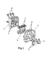
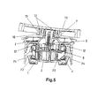
- the object of the invention relates to a switch for electrical installations of the type comprising a casing made from electrically insulating material formed by a hollow body (1) which is closed with a lid (2), the body (1) forming cavities (3) for housing connection terminals (4) of external electric cables (5), an operating mechanism formed by a rocker (6) provided with movable contacts (7) which are susceptible to bearing against and separating from corresponding fixed contacts (8) linked with the terminals (4) being linked with said terminals (4), said rocker (6) being able to be actuated by means of a rocker element (9) to which an operating key (10)is coupled.
- the rocker of the operating mechanism rocker (6) is arranged above the position of the terminals (4), such that the terminals (4) of both sides of the switch are close to each other, the switch thereby having a reduced length, being able to be coupled to several types of securing frames (11) for the assembly in the application installations.
- the switch is fixed on the frame (11) in which it will be incorporated by means of anchoring pins (2.1) provided with an end tooth (2.2) which the lid (2) has, which are inserted and establish a retaining catch in respective housings (11.1) of the assembly frame (11), as seen in Figures 6 and 7 .
- the size of the end tooth (2.2) of the pins (2) determines how easy or difficult it is to disassemble the switch from the frame (11) once the assembly has been done.
- the operating key (10) is coupled by means of fitting pins (13) of the key (10) itself in cavities (14) the rocker element (9) has, said cavities (14) forming teeth (15) collaborating with corresponding teeth (16) of the pins of the key (10), thus establishing a retaining catch securing the assembly of the key (10).
- rocker element (9) being able to be in a single part formed by two attached parts for actuating a single simple mechanism of the switch as in the embodiment of Figure 8 , or for simultaneously actuating two integrated mechanism in the switch as in the embodiment of Figure 1 ; said rocker element (9) also being able to be in two independent parts for individually actuating two integrated mechanisms in the switch as in the embodiment of Figure 9 , in this case two respective operating half keys (10) coupled to the mentioned independent parts of the rocker element (9) being arranged.
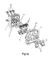
- the switch can equally be formed with an arrangement of related mechanisms for establishing a switching arrangement between two switches in the application installations, and also with a crossover arrangement between mechanisms incorporated in the switch itself by means of cross connection flat bars (17), as in the embodiment of figures 10 and 11 .
- the body (1) of the casing forms channels (18) in which said flat bars (17) are held by means of the insertion slot, without the need for overmoulding.
- the switch can be complemented with a light signalling device, a light device (19) externally connected by means of a cable (20) being able to be incorporated as depicted in Figure 12 , but a light device (21) connected through the lid (2) of the casing can also be placed as shown in Figure 13 , the lid (2) being provided with holes (22) for that purpose through which said light device (21) is connected.
- the terminals (4) for connecting external cables (5) can be pressure terminals with screws, but they are preferably of the pressure type through a strip (23) for automatic connecting by means of inserting the cable (5) to be connected as seen in Figure 4 , each borne (4) having a lever (24) allowing to act against the strip (23) to perform the disconnection.
- the terminals (4) can be overmoulded in an block (25) made from electrically insulating material which is inserted in the body (1) of the casing, the terminals being (4) positioned in the same way as when the terminals (4) are independent, but with overmoulding on said block (25), the terminals (4) are protected to prevent them from possibly being affected and short-circuiting due to the liquid or semi-liquid products used for helping pass the cables (5) through the assembly tubes in the installation and can enter the switch when connecting said cables (5) in the terminals (4).
Landscapes
- Switch Cases, Indication, And Locking (AREA)
- Manufacture Of Switches (AREA)
Applications Claiming Priority (1)
| Application Number | Priority Date | Filing Date | Title |
|---|---|---|---|
| ES201001107A ES2400108B1 (es) | 2010-08-26 | 2010-08-26 | Interruptor para instalaciones eléctricas. |
Publications (2)
| Publication Number | Publication Date |
|---|---|
| EP2423937A2 true EP2423937A2 (fr) | 2012-02-29 |
| EP2423937A3 EP2423937A3 (fr) | 2012-04-04 |
Family
ID=44503636
Family Applications (1)
| Application Number | Title | Priority Date | Filing Date |
|---|---|---|---|
| EP11177090A Ceased EP2423937A3 (fr) | 2010-08-26 | 2011-08-10 | Commutateur pour installations électriques |
Country Status (2)
| Country | Link |
|---|---|
| EP (1) | EP2423937A3 (fr) |
| ES (1) | ES2400108B1 (fr) |
Cited By (5)
| Publication number | Priority date | Publication date | Assignee | Title |
|---|---|---|---|---|
| EP2648200A1 (fr) * | 2012-04-05 | 2013-10-09 | Abb Ag | Insert de commutateur d'un commutateur d'installation électrique |
| CN104733209A (zh) * | 2013-12-19 | 2015-06-24 | 矢崎总业株式会社 | 开关结构 |
| IT202200016392A1 (it) * | 2022-08-02 | 2024-02-02 | Bticino Spa | Dispositivo elettrico modulare per il controllo e/o la distribuzione di energia elettrica |
| EP4485491A1 (fr) * | 2023-06-30 | 2025-01-01 | Schneider Electric España, S.A. | Commutateur électrique polyvalent |
| EP4550581A1 (fr) * | 2023-10-30 | 2025-05-07 | Schneider Electric Industries Sas | Dispositif électrique ayant un mécanisme d'installation de fil |
Family Cites Families (5)
| Publication number | Priority date | Publication date | Assignee | Title |
|---|---|---|---|---|
| DE8428052U1 (de) * | 1984-09-24 | 1984-12-20 | Heinrich Kopp Gmbh & Co Kg, 8756 Kahl | Wippenschalter-Helligkeitssteller-Kombination |
| DE3706681C2 (de) * | 1987-03-02 | 1993-11-25 | Eaton Controls Gmbh | Elektrischer Schalter mit Leuchtanzeige |
| US6066815A (en) * | 1998-08-24 | 2000-05-23 | Illinois Tool Works Inc. | Electrical connector-power switch module |
| US6919523B1 (en) * | 2004-02-06 | 2005-07-19 | Defond Components Limited | Electrical switch |
| MA28719B1 (fr) * | 2005-12-02 | 2007-07-02 | Simon Sa | Mecanisme electrique encastrable et plurifonctionnel |
-
2010
- 2010-08-26 ES ES201001107A patent/ES2400108B1/es active Active
-
2011
- 2011-08-10 EP EP11177090A patent/EP2423937A3/fr not_active Ceased
Non-Patent Citations (1)
| Title |
|---|
| None |
Cited By (7)
| Publication number | Priority date | Publication date | Assignee | Title |
|---|---|---|---|---|
| EP2648200A1 (fr) * | 2012-04-05 | 2013-10-09 | Abb Ag | Insert de commutateur d'un commutateur d'installation électrique |
| RU2607703C2 (ru) * | 2012-04-05 | 2017-01-10 | Абб Аг | Переключающая вставка электрического установочного переключателя |
| CN104733209A (zh) * | 2013-12-19 | 2015-06-24 | 矢崎总业株式会社 | 开关结构 |
| IT202200016392A1 (it) * | 2022-08-02 | 2024-02-02 | Bticino Spa | Dispositivo elettrico modulare per il controllo e/o la distribuzione di energia elettrica |
| EP4318523A1 (fr) * | 2022-08-02 | 2024-02-07 | Bticino S.P.A. | Un dispositif électrique modulaire pour contrôler et/ou distribuer l'électricité |
| EP4485491A1 (fr) * | 2023-06-30 | 2025-01-01 | Schneider Electric España, S.A. | Commutateur électrique polyvalent |
| EP4550581A1 (fr) * | 2023-10-30 | 2025-05-07 | Schneider Electric Industries Sas | Dispositif électrique ayant un mécanisme d'installation de fil |
Also Published As
| Publication number | Publication date |
|---|---|
| ES2400108B1 (es) | 2013-12-16 |
| EP2423937A3 (fr) | 2012-04-04 |
| ES2400108A1 (es) | 2013-04-05 |
Similar Documents
| Publication | Publication Date | Title |
|---|---|---|
| JP6454036B2 (ja) | 直流配線用遮断器 | |
| EP2423937A2 (fr) | Commutateur pour installations électriques | |
| US7609137B2 (en) | Electrical switchgear | |
| JP2014049376A (ja) | コネクタの接続構造 | |
| US20130217276A1 (en) | Electrical wall bushing terminal | |
| CN100485845C (zh) | 具有用于控制电磁驱动装置的连接组件的接触器 | |
| JPH10247538A (ja) | プリント板又は電気装置のためのソケツト端子 | |
| EP3417469B1 (fr) | Interrupteur à bouton-poussoir avec système de guidage anti-brouillage | |
| KR880005640A (ko) | 상호 교환가능한 전자개폐 스위치장치 | |
| US10163593B2 (en) | Temperature switch | |
| US10418758B2 (en) | Electrical system comprising an electrical unit and an interchangeable connection module | |
| JP2006012842A (ja) | リレー及びコネクタ組立体 | |
| CN111725035B (zh) | 快速连结端子单元及电路断路装置 | |
| EP2261943B1 (fr) | Terminal d'insertion et commutateur | |
| WO2014053424A1 (fr) | Connecteur et kit de construction pour un connecteur | |
| US5605478A (en) | Means for attaching a connector body to an electric device | |
| JP2004327127A (ja) | ヒューズ誤挿入防止栓 | |
| US20090298309A1 (en) | Electric Connection Box | |
| CN214672449U (zh) | 漏电断路器的取电机构 | |
| US9984845B2 (en) | Circuit breaker with interference fit socket | |
| CA2637423A1 (fr) | Dispositif de commutation de distribution electrique avec boitier isolant | |
| EP0986136A2 (fr) | Dispositif de liaison de sécurité en particulier pour appareils électriques modulaires | |
| CN216054536U (zh) | 断路器 | |
| KR101651749B1 (ko) | 회로 차단기 | |
| EP3608934A1 (fr) | Module de commutateur de fusible |
Legal Events
| Date | Code | Title | Description |
|---|---|---|---|
| AK | Designated contracting states |
Kind code of ref document: A2 Designated state(s): AL AT BE BG CH CY CZ DE DK EE ES FI FR GB GR HR HU IE IS IT LI LT LU LV MC MK MT NL NO PL PT RO RS SE SI SK SM TR |
|
| AX | Request for extension of the european patent |
Extension state: BA ME |
|
| PUAI | Public reference made under article 153(3) epc to a published international application that has entered the european phase |
Free format text: ORIGINAL CODE: 0009012 |
|
| PUAL | Search report despatched |
Free format text: ORIGINAL CODE: 0009013 |
|
| AK | Designated contracting states |
Kind code of ref document: A3 Designated state(s): AL AT BE BG CH CY CZ DE DK EE ES FI FR GB GR HR HU IE IS IT LI LT LU LV MC MK MT NL NO PL PT RO RS SE SI SK SM TR |
|
| AX | Request for extension of the european patent |
Extension state: BA ME |
|
| RIC1 | Information provided on ipc code assigned before grant |
Ipc: H01H 23/24 20060101ALN20120227BHEP Ipc: H01H 23/14 20060101ALN20120227BHEP Ipc: H01H 23/04 20060101ALN20120227BHEP Ipc: H01H 23/02 20060101ALN20120227BHEP Ipc: H01H 23/20 20060101AFI20120227BHEP |
|
| 17P | Request for examination filed |
Effective date: 20121002 |
|
| 17Q | First examination report despatched |
Effective date: 20130318 |
|
| STAA | Information on the status of an ep patent application or granted ep patent |
Free format text: STATUS: THE APPLICATION HAS BEEN REFUSED |
|
| 18R | Application refused |
Effective date: 20141227 |