EP4485491A1 - Commutateur électrique polyvalent - Google Patents
Commutateur électrique polyvalent Download PDFInfo
- Publication number
- EP4485491A1 EP4485491A1 EP23382675.9A EP23382675A EP4485491A1 EP 4485491 A1 EP4485491 A1 EP 4485491A1 EP 23382675 A EP23382675 A EP 23382675A EP 4485491 A1 EP4485491 A1 EP 4485491A1
- Authority
- EP
- European Patent Office
- Prior art keywords
- rocker arm
- actuation
- push plate
- electrical switch
- fixing
- Prior art date
- Legal status (The legal status is an assumption and is not a legal conclusion. Google has not performed a legal analysis and makes no representation as to the accuracy of the status listed.)
- Pending
Links
Images


Classifications
-
- H—ELECTRICITY
- H01—ELECTRIC ELEMENTS
- H01H—ELECTRIC SWITCHES; RELAYS; SELECTORS; EMERGENCY PROTECTIVE DEVICES
- H01H23/00—Tumbler or rocker switches, i.e. switches characterised by being operated by rocking an operating member in the form of a rocker button
- H01H23/02—Details
- H01H23/12—Movable parts; Contacts mounted thereon
- H01H23/14—Tumblers
- H01H23/143—Tumblers having a generally flat elongated shape
-
- H—ELECTRICITY
- H01—ELECTRIC ELEMENTS
- H01H—ELECTRIC SWITCHES; RELAYS; SELECTORS; EMERGENCY PROTECTIVE DEVICES
- H01H11/00—Apparatus or processes specially adapted for the manufacture of electric switches
- H01H11/0006—Apparatus or processes specially adapted for the manufacture of electric switches for converting electric switches
- H01H11/0018—Apparatus or processes specially adapted for the manufacture of electric switches for converting electric switches for allowing different operating parts
-
- H—ELECTRICITY
- H01—ELECTRIC ELEMENTS
- H01H—ELECTRIC SWITCHES; RELAYS; SELECTORS; EMERGENCY PROTECTIVE DEVICES
- H01H23/00—Tumbler or rocker switches, i.e. switches characterised by being operated by rocking an operating member in the form of a rocker button
- H01H23/02—Details
-
- H—ELECTRICITY
- H01—ELECTRIC ELEMENTS
- H01H—ELECTRIC SWITCHES; RELAYS; SELECTORS; EMERGENCY PROTECTIVE DEVICES
- H01H23/00—Tumbler or rocker switches, i.e. switches characterised by being operated by rocking an operating member in the form of a rocker button
- H01H23/24—Tumbler or rocker switches, i.e. switches characterised by being operated by rocking an operating member in the form of a rocker button with two operating positions
Definitions
- the present invention relates to electrical switches which are arranged on walls for activating and deactivating functions, such as for switching light sources on and off, said switches comprising different actuation plates or buttons and a swiveling mechanism which is actuated by means of the button to change between positions for the electrical activation and deactivation of the function controlled with the switch, with there being different actuation alternatives.
- Switches with different ways of actuation on the swiveling mechanism or rocker arm which is actuated by means of an actuation button normally has a flat rectangular or circular shape that acts directly on the rocker arm when pushed, being the most commonly used configuration for wall-mounted electrical switches, and on which there is finally arranged the aesthetic framework fixed to the frame of the electrical switch.
- Another alternative to said actuation button is a lever that protrudes from the switch, which was formerly the most widespread design and is currently regaining relevance, in which the pivoting movement of the lever acts on the rocker arm for connection or disconnection, and the aesthetic framework is also arranged on said lever button.
- actuation button is the one described in European patent application EP23382566.0 , which comprises a mechanism for reducing the angle of inclination of the button, with the actuation button occupying the entire contour of the frame and therefore dispensing with the aesthetic framework, such that it has a coupling panel for coupling the button to the frame for pivoting, and which acts on the rocker arm by means of lever parts.
- the present invention provides a multipurpose electrical switch with a T-shaped actuation rocker arm assembled in a base box in a swiveling manner between positions for the connection and disconnection of the switch, said base box being assembled on a frame that can be fixed to the wall, and comprising a push plate that can be fixed to said actuation rocker arm, wherein the actuation rocker arm comprises first fixing means for the detachable fixing of a first standard actuation push plate, and second fixing means for the detachable fixing of a second actuation push plate for actuation by means of a lever.
- a standard actuation push plate is understood to be a plate having normally square or circular flat geometry which, when pushed, acts directly on the actuation rocker arm for the connection and disconnection of the switch.
- An actuation push plate for actuation by means of a lever is understood to be the lever button or plate which, when pivoted, causes the lever to move the actuation rocker arm for the connection and disconnection of the switch.
- the aesthetics thereof can be modified for two different actuation modes without having to change the entire switch box, simply by changing the standard plate or button, which comprises fixing means in correspondence with the actuation rocker arm, changing it for the lever plate which comprises other fixing means in correspondence with the actuation rocker arm.
- the first fixing means are at least one projection at each end of the actuation rocker arm for the snap-fitted fixing of the first push plate which in turn comprises corresponding fitting pins
- the second fixing means being at least one recess on each side of the rocker arm for the snap-fitted fixing of the second push plate which in turn comprises corresponding fitting pins.
- the electrical switch object of the invention also serves for operation with a button or plate as described in European patent application EP23382566.0 , such that the rocker arm comprises at each of the ends a step with a geometry in correspondence with the actuation end of the corresponding push levers of a third push plate of those which comprise a coupling panel for fixing to the frame on which the third push plate is secured in a swiveling assembly and with respective levers secured in rotary attachment on said coupling panel.
- the actuation rocker arm is adapted with said step for a correct transmission of the movement from the plate to the actuation rocker arm.
- the electrical switch comprises a set of terminals which comprises at the upper contact end thereof a fixed contact arranged on an inclined plane, and the electrical switch comprising a contact rocker arm, preferably in the form of a flat, which is supported for pivoting on a support element (9) arranged in the lower portion of said set of terminals (7), and the contact rocker arm (8) swiveling between the positions for connection and disconnection by means of the action of a contact spring (10) of the actuation rocker arm (1), the contact spring (10) being supported on the contact rocker arm (8) according to an intermediate height of the set of terminals (7).
- the contact rocker arm having a recess for the support of the contact spring arranged at an intermediate height of the terminal assembly, being understood as a height lower than that reached by the set of terminals in the arrangement thereof in the base box.
- the support element will preferably have a V shape to facilitate swiveling between the positions for connection and disconnection.
- the depth of the base box or switch box is reduced, being compatible with any of the exchangeable actuation plate options.
- the impact noise on connection/disconnection contact is reduced, having a lateral rocking which reduces the rocking angle and impact speed with respect to the known set of terminals in which the contact rocker arm is arranged parallel to the frame arrangement.
- the contact rocker arm is arranged vertically as a prolongation of the actuation rocker arm, i.e., substantially perpendicular to the frame arrangement, such that the transmission of forces reduces the impact sound, with the fixed and movable connection contacts therefore also lasting longer.
- the third actuation plate contributes to reducing the pivoting angle of the push plate since the contact rocker arm and accordingly the actuation rocker arm have a lower degree of rocking.
- the contact spring is arranged directly on the contact rocker arm, being housed only in the housing of the actuation rocker arm to prevent it from coming out.
- the actuation rocker arm comprises a housing covering the spring along the entire length thereof, such that it acts to house and guide the spring, preventing it from coming out in the pivoting movement for connection and disconnection.
- it comprises disengagement levers arranged in a disengagement block which can be removably fixed on the set of terminals, and with a window for accessing the contact spring of the actuation rocker arm.
- the disengagement levers which in the state of the art were pivotably arranged on the base box but which, in the embodiments in which the terminals are overmolded in a block made of an electrically insulating material, do not allow the replacement of said lever, which sometimes, in the event of breakage, rendered the switch unusable as engagement is not allowed.
- the disengagement block is fixed on the set of terminals, by means of a fitting having dimensions in correspondence with the set of terminals, and having the window which allows access to the contact rocker arm, which was not possible in the state of the art in accordance with the horizontal arrangement of the contact rocker arm.
- a multipurpose electrical switch for different type of actuation plates with one and the same block of switch base box and with robustness that allows extending its service life is therefore obtained.
- the electrical switch object of the invention is configured so that three different models of push plates (4, 5, 6) can be exchangeable, with the designs being the most widely available on the market.
- the first button design depicted in Figure 1A with the first actuation plate (4) refers to standard buttons for an electrical connection/disconnection switch.
- the second button design depicted in Figure 1B with the second actuation plate (5) refers to electrical switches that can be actuated by means of a lever.
- the third button design depicted in Figure 1C with the third actuation plate (6) refers to buttons that completely cover the switch, combining the aesthetic framework and the button in a single element, and seek to achieve the smallest possible swiveling angle of the button for improved aesthetic.
- the novelty of the electrical switch object of the invention is the arrangement of a multipurpose electrical switch, which allows aesthetic and functional exchange simply by exchanging the actuation plate, such that a user can perform said change without having to disassemble the electrical switch.
- the risk of the user having to possibly exchange the actuation plate if he/she had to change the base box (2) or the entire switch box like in the state of the art is thereby prevented, since in this case the entire switch box would have to be disconnected with the associated push plate by disconnecting the wiring from the mains.
- the cost to perform said change is reduced, given that fewer elements are required for the exchange.
- production cost savings is achieved for the same reason, manufacturing only an electrical switch model configured for exchange with different push plates (4, 5, 6).
- the multipurpose electrical switch comprises an actuation rocker arm (1) configured for fixing and interaction with the different push plates (4, 5, 6).
- the base box (2) with its actuation rocker arm (1) is fixed to the frame (3), said actuation rocker arm (1) acting between a position for connection and another position for disconnection.
- the first push plate (4) is fixed in this actuation rocker arm (1), to that end, the actuation rocker arm (1) comprises at each of the longitudinal ends thereof at least one projection (1.1), said projection being configured for the snap-fitted fixing of a corresponding pin (4.1) of the first push plate (4).
- the aesthetic framework (13) will then be fixed as is performed usually. Said ends are understood to mean those located in the end positions of the swiveling actuation rocker arm (1), corresponding with the larger dimension of the actuation rocker arm (1) and therefore being understood as the longitudinal direction thereof.
- the first push plate (4) therefore being able to be fixed in a detachable manner for possible exchange.
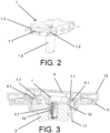
- the rocker arm comprises at least one recess (1.2) and preferably two recesses (1.2) on each side of the actuation rocker arm (1) for the snap-fitted fixing of the fitting pins (5.1) in correspondence with the recesses (1.2), such that the pins are introduced by clipping into said recesses (1.2), with the second push plate (5) thus being fixed.
- Sides of the actuation rocker arm (1) are understood to mean the end surfaces thereof in the direction perpendicular to the longitudinal direction thereof.
- the recesses (1.2) will be positioned as close as possible to the ends of the actuation rocker arm (1) in order to achieve an optimum lever effect.
- the second push plate (5) where the fitting pins (5.1) can be seen in greater detail arranged in end positions of the second push plate (5) and oriented towards the inside to better protect the fixing.
- the second push plate (5) comprises a side edge which reinforces the protection of said fitting pins (5.1).
- Said recesses (1.2) of the actuation rocker arm (1) can be better seen in Figure 2 .
- an aesthetic plate (5') with a hole for the passage of the lever will be fixed to the frame (3), proceeding subsequently to fix the aesthetic framework (13) to the frame (3), for complete installation.
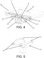
- a third actuation plate (6) such as the one described in European patent application EP23382566.0 , in which once the assembly of the base box (2) with the actuation rocker arm (1) and the frame (3) is assembled, a coupling panel (6.2) is fixed to the frame (3), with the third push plate (6) which has two lever parts (6.1) secured in rotary attachment on said coupling panel (6.2) being fixed in a swiveling assembly on said coupling panel (6.2).
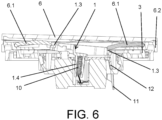
- the actuation rocker arm (1) comprises a step (1.3) at each end configured for the contact of the end of the lever part (6.1), such that said step (1.3) has a shape in correspondence with the end of the lever part (6.1) and furthermore has a width dimension which allows the support of the lever part (6.1) to perform swiveling contact of the actuation rocker arm (1) without said lever part (6.1) jamming up.
- the actuation rocker arm (1) comprises a step (1.3) at each end configured for the contact of the end of the lever part (6.1), such that said step (1.3) has a shape in correspondence with the end of the lever part (6.1) and furthermore has a width dimension which allows the support of the lever part (6.1) to perform swiveling contact of the actuation rocker arm (1) without said lever part (6.1) jamming up.
- the end of the lever part (6.1) being in contact with the wall of the step (1.3) that acts as a stop.
- the third push plate (6) before being pushed can be seen,
- the actuation rocker arm (1) comprises a housing (1.4) covering the spring along the entire length thereof in the form of a sheath, such that it acts to house and guide the spring (10), preventing it from coming out in the pivoting movement of the actuation rocker arm (1) for connection and disconnection.
- the electrical switch of the invention comprises a set of terminals (7) which comprises in the upper contact end thereof a fixed contact (7.1) arranged on an inclined plane, and with a contact rocker arm (8) with movable contacts (8.1) swivels between the positions for connection and disconnection by means of the action of a contact spring (10) of the actuation rocker arm (1), such that the contact spring (10) is supported on the contact rocker arm (8) according to an intermediate height of the set of terminals (7), with the actuation rocker arm (1) being partially introduced in the set of terminals (7), and therefore reducing the height of the electrical switch.
- Said contact rocker arm (8) is supported for pivoting in a support element (9) arranged in the lower portion of said set of terminals (7), and with a preferred V-shaped configuration.
- a more robust base box (2) with the use thereof reinforced for a longer service life for interchangeability with different push plates (4, 5, 6) is thereby achieved.
- Said disengagement block (12) comprises a flat upper surface for contact with the upper surface of the set of terminals (7) and with a window (12.1) for accessing the contact spring (10) of the actuation rocker arm, and the disengagement levers (11) being positioned once the disengagement block (12) is fitted.
- the disengagement levers (11) are part of the block (12), being able to be removed in the event of breakage or malfunction, unlike known solutions in which the disengagement levers (11) were fixed without possibility of access to same and therefore the removal or exchange thereof is not possible.
- This configuration reinforces the robustness of the assembly of the base box (2) for use with exchangeable push plates.
Landscapes
- Engineering & Computer Science (AREA)
- Manufacturing & Machinery (AREA)
- Switch Cases, Indication, And Locking (AREA)
Priority Applications (1)
| Application Number | Priority Date | Filing Date | Title |
|---|---|---|---|
| EP23382675.9A EP4485491A1 (fr) | 2023-06-30 | 2023-06-30 | Commutateur électrique polyvalent |
Applications Claiming Priority (1)
| Application Number | Priority Date | Filing Date | Title |
|---|---|---|---|
| EP23382675.9A EP4485491A1 (fr) | 2023-06-30 | 2023-06-30 | Commutateur électrique polyvalent |
Publications (1)
| Publication Number | Publication Date |
|---|---|
| EP4485491A1 true EP4485491A1 (fr) | 2025-01-01 |
Family
ID=87429373
Family Applications (1)
| Application Number | Title | Priority Date | Filing Date |
|---|---|---|---|
| EP23382675.9A Pending EP4485491A1 (fr) | 2023-06-30 | 2023-06-30 | Commutateur électrique polyvalent |
Country Status (1)
| Country | Link |
|---|---|
| EP (1) | EP4485491A1 (fr) |
Citations (4)
| Publication number | Priority date | Publication date | Assignee | Title |
|---|---|---|---|---|
| EP1376631A1 (fr) * | 2002-06-20 | 2004-01-02 | ABB PATENT GmbH | Montage d'au moins un élément basculant sur la bascule de commutation d'un commutateur électrique |
| US20070125635A1 (en) * | 2005-12-02 | 2007-06-07 | Capella Joaquin A | Multi-functional, flush-fitting electrical mechanism |
| EP2423937A2 (fr) * | 2010-08-26 | 2012-02-29 | Schneider Electric Espana, S.A. | Commutateur pour installations électriques |
| US20160225553A1 (en) * | 2015-02-03 | 2016-08-04 | Legrand France | Driver for an electrical switch and an electrical switch including such a driver |
-
2023
- 2023-06-30 EP EP23382675.9A patent/EP4485491A1/fr active Pending
Patent Citations (4)
| Publication number | Priority date | Publication date | Assignee | Title |
|---|---|---|---|---|
| EP1376631A1 (fr) * | 2002-06-20 | 2004-01-02 | ABB PATENT GmbH | Montage d'au moins un élément basculant sur la bascule de commutation d'un commutateur électrique |
| US20070125635A1 (en) * | 2005-12-02 | 2007-06-07 | Capella Joaquin A | Multi-functional, flush-fitting electrical mechanism |
| EP2423937A2 (fr) * | 2010-08-26 | 2012-02-29 | Schneider Electric Espana, S.A. | Commutateur pour installations électriques |
| US20160225553A1 (en) * | 2015-02-03 | 2016-08-04 | Legrand France | Driver for an electrical switch and an electrical switch including such a driver |
Similar Documents
| Publication | Publication Date | Title |
|---|---|---|
| EP2031614B1 (fr) | Déclencheur | |
| CA3059183C (fr) | Ensemble de commutation et d'utilisation d'un interrupteur | |
| MX2012012388A (es) | Dispositivos electricos con armazones de accionador removibles. | |
| CN110709955A (zh) | 控制设备 | |
| JP2010232157A (ja) | 押しボタンスイッチ | |
| JP2003151403A (ja) | スイッチ | |
| GB1584021A (en) | Electrical switch | |
| CN103380472B (zh) | 钥匙卡插入取电开关 | |
| PL208866B1 (pl) | Zespół elementów konstrukcyjnych do montażu przełączników niskonapięciowych | |
| CN106663560A (zh) | 用于电气开关的面板组件和具有这种面板组件的电气开关 | |
| EP4439609B1 (fr) | Interrupteur électrique | |
| JP2012119213A (ja) | スイッチ装置 | |
| CN105845470B (zh) | 用于电气开关的驱动器和具有这种驱动器的电气开关 | |
| EP4328950B1 (fr) | Interrupteur électrique | |
| CN209881148U (zh) | 模数化终端组合电器箱 | |
| JP5191952B2 (ja) | テーブルタップ | |
| CN102412079B (zh) | 具有机械式信号显示部的按键 | |
| US5150092A (en) | Control button adaptor for electric control apparatus | |
| EP0577502A1 (fr) | Tableau de commande à touches, en particulier pour la commande d'une installation de climatisation de l'habitacle d'un véhicule automobile | |
| JP2008130531A (ja) | 押釦構造およびその構造を使用したトイレ用壁付けリモコン | |
| JP4655097B2 (ja) | スイッチ装置 | |
| JP7847063B2 (ja) | リモコン | |
| JP7832671B2 (ja) | リモコン | |
| EP4478558B1 (fr) | Prise électrique | |
| EP4318523A1 (fr) | Un dispositif électrique modulaire pour contrôler et/ou distribuer l'électricité |
Legal Events
| Date | Code | Title | Description |
|---|---|---|---|
| PUAI | Public reference made under article 153(3) epc to a published international application that has entered the european phase |
Free format text: ORIGINAL CODE: 0009012 |
|
| STAA | Information on the status of an ep patent application or granted ep patent |
Free format text: STATUS: THE APPLICATION HAS BEEN PUBLISHED |
|
| AK | Designated contracting states |
Kind code of ref document: A1 Designated state(s): AL AT BE BG CH CY CZ DE DK EE ES FI FR GB GR HR HU IE IS IT LI LT LU LV MC ME MK MT NL NO PL PT RO RS SE SI SK SM TR |
|
| STAA | Information on the status of an ep patent application or granted ep patent |
Free format text: STATUS: REQUEST FOR EXAMINATION WAS MADE |
|
| 17P | Request for examination filed |
Effective date: 20250630 |