EP2424079A1 - Moteur et appareil électrique et procédé pour la fabrication du moteur - Google Patents
Moteur et appareil électrique et procédé pour la fabrication du moteur Download PDFInfo
- Publication number
- EP2424079A1 EP2424079A1 EP09843642A EP09843642A EP2424079A1 EP 2424079 A1 EP2424079 A1 EP 2424079A1 EP 09843642 A EP09843642 A EP 09843642A EP 09843642 A EP09843642 A EP 09843642A EP 2424079 A1 EP2424079 A1 EP 2424079A1
- Authority
- EP
- European Patent Office
- Prior art keywords
- motor
- stator
- wiring board
- printed wiring
- conductive sheet
- Prior art date
- Legal status (The legal status is an assumption and is not a legal conclusion. Google has not performed a legal analysis and makes no representation as to the accuracy of the status listed.)
- Granted
Links
Images




Classifications
-
- H—ELECTRICITY
- H02—GENERATION; CONVERSION OR DISTRIBUTION OF ELECTRIC POWER
- H02K—DYNAMO-ELECTRIC MACHINES
- H02K11/00—Structural association of dynamo-electric machines with electric components or with devices for shielding, monitoring or protection
- H02K11/30—Structural association with control circuits or drive circuits
- H02K11/33—Drive circuits, e.g. power electronics
-
- H—ELECTRICITY
- H02—GENERATION; CONVERSION OR DISTRIBUTION OF ELECTRIC POWER
- H02K—DYNAMO-ELECTRIC MACHINES
- H02K11/00—Structural association of dynamo-electric machines with electric components or with devices for shielding, monitoring or protection
- H02K11/01—Structural association of dynamo-electric machines with electric components or with devices for shielding, monitoring or protection for shielding from electromagnetic fields, i.e. structural association with shields
- H02K11/014—Shields associated with stationary parts, e.g. stator cores
- H02K11/0141—Shields associated with casings, enclosures or brackets
-
- H—ELECTRICITY
- H02—GENERATION; CONVERSION OR DISTRIBUTION OF ELECTRIC POWER
- H02K—DYNAMO-ELECTRIC MACHINES
- H02K2211/00—Specific aspects not provided for in the other groups of this subclass relating to measuring or protective devices or electric components
- H02K2211/03—Machines characterised by circuit boards, e.g. pcb
-
- H—ELECTRICITY
- H02—GENERATION; CONVERSION OR DISTRIBUTION OF ELECTRIC POWER
- H02K—DYNAMO-ELECTRIC MACHINES
- H02K5/00—Casings; Enclosures; Supports
- H02K5/04—Casings or enclosures characterised by the shape, form or construction thereof
- H02K5/16—Means for supporting bearings, e.g. insulating supports or means for fitting bearings in the bearing-shields
- H02K5/173—Means for supporting bearings, e.g. insulating supports or means for fitting bearings in the bearing-shields using bearings with rolling contact, e.g. ball bearings
- H02K5/1732—Means for supporting bearings, e.g. insulating supports or means for fitting bearings in the bearing-shields using bearings with rolling contact, e.g. ball bearings radially supporting the rotary shaft at both ends of the rotor
-
- Y—GENERAL TAGGING OF NEW TECHNOLOGICAL DEVELOPMENTS; GENERAL TAGGING OF CROSS-SECTIONAL TECHNOLOGIES SPANNING OVER SEVERAL SECTIONS OF THE IPC; TECHNICAL SUBJECTS COVERED BY FORMER USPC CROSS-REFERENCE ART COLLECTIONS [XRACs] AND DIGESTS
- Y10—TECHNICAL SUBJECTS COVERED BY FORMER USPC
- Y10T—TECHNICAL SUBJECTS COVERED BY FORMER US CLASSIFICATION
- Y10T29/00—Metal working
- Y10T29/49—Method of mechanical manufacture
- Y10T29/49002—Electrical device making
- Y10T29/49009—Dynamoelectric machine
Definitions
- the present invention relates to a motor mounting a printed wiring board having a drive circuit, using a rolling bearing, and driven by an inverter. Further, the present invention also relates to a method of manufacturing the motor and electric equipment such as an air conditioner, etc. mounting the motor.
- carrier frequency of the inverter when driving a motor using an inverter, in order to reduce noise of the motor generated with switching of a transistor, carrier frequency of the inverter is set high.
- the carrier frequency is set high or a source voltage is high, a potential difference between an inner ring and an outer ring of a rolling bearing which supports a shaft becomes large, and thus electric current easily flows into the rolling bearing.
- the electric current flowing through the rolling bearing generates corrosion so-called electric corrosion on rolling surfaces of both races of the inner ring and the outer ring and a rolling element (balls or rollers rolling between the inner and outer rings), thereby degrading the durability of the rolling bearing.
- large noise may occur from the motor due to the generation of the electric corrosion.
- Various kinds of motors which solve the above problems have been proposed.
- a motor which is structured by a stator core; a stator molded to form one body with a stator winding wound to the stator core using insulating resin; a rotor having a shaft; a first bearing and a second bearing for supporting the shaft; a metal bracket coupled to the stator and retaining at least either of the first bearing and the second bearing; and a conductive member for short-circuiting the stator core and the metal bracket (for instance, refer to Patent Literature 1).
- a bracket of an output side and a bracket of the opposite side to the output side attached to a frame are short-circuited by a conductive tape, and the conductive tape is bonded to the outside of the frame; there is a problem that when electric potential is generated in a rotor, electric current flows through a bearing, thereby causing electric corrosion.
- the present invention aims to provide a motor, a method of manufacturing the motor, and an electric equipment that can reduce electric current flowing through a bearing which causes abnormal abrasion of the bearing and suppress electric corrosion of the bearing without degrading the productivity or the quality.
- a motor includes:
- the motor of the invention is characterized in that the conductive sheet and the stator core are electrically connected.
- the motor of the invention is characterized in that the conductive sheet and the stator core are electrically connected using a connecting pin which is conductive.
- the motor of the invention is characterized in that the connecting pin is fixed to the insulating part.
- the motor of the invention is characterized in that the printed wiring board is provided with a through-hole for passing the connecting pin through.
- the motor of the invention is characterized in that a flexible wiring board having at least a conductive layer and an insulating layer is used for the conductive sheet.
- the motor of the invention is characterized in that the conductive sheet is provided with a through-hole for passing a component mounted on the printed wiring board through.
- the motor of the invention is characterized in that the conductive sheet has an almost same area as the printed wiring board.
- An electric equipment of the present invention is characterized in that the above motor is mounted.
- a method of manufacturing a motor is the method of manufacturing the above motor, and the method includes steps of:
- the motor related to the present invention is provided with the metal bracket and the conductive sheet arranged between the printed wiring board and the bracket, and thus it is possible to obtain effect to reduce electric current flowing through the bearing and prevent abnormal sound due to abnormal abrasion.
- Figs. 1 to 8 show the first embodiment;
- Fig. 1 is a cross section view of a motor 100;
- Fig. 2 is a partial enlarged cross section view of a surrounding part of a connecting pin 61;
- Fig. 3 is a plan view showing status in which after inserting a rotor assembly 20 to a molded stator 10, a printed wiring board 45 is attached;
- Fig. 4 is a cross section view of a conductive sheet 60;
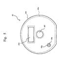
- Fig. 5 is a plan view of the conductive sheet 60;
- Fig. 6 is a block diagram of a drive circuit 200 for driving the motor 100;
- Fig. 7 is a perspective view of an outer appearance of an inverter IC 49a; and
- Fig. 8 is a diagram of a manufacturing process of the motor 100.
- a structure of the motor 100 will be explained with reference to Fig. 1 ; first, an assembling procedure of the motor 100 will be discussed before explaining the structure of motor 100.
- an insulating part 43 is applied to teeth of a stator core 41, and a winding 42 of a concentrated winding system is wound, forming a stator assembly 40.
- mold forming of the stator assembly 40 to which the winding 42 has been finished is done using mold compound 50, thereby forming a molded stator 10 (an example of a stator).
- mold compound 50 for instance, thermosetting resin such as unsaturated polyester resin is used.
- the molded stator 10 has an opening at one end in the axial direction.
- the other end of the molded stator 10 in the axial direction may be closed, or may be provided with a hole which is large enough to insert the shaft 23. By opening the hole, it is possible to increase the flexibility to decide the position for providing load, for instance, a fan, etc.
- the rotor assembly 20 is inserted to the molded stator 10 from the opening part.
- the rotor assembly 20 includes at least a rotor 20a, bearings 21a and 21b (rolling bearings), and a shaft 23.
- the rotor assembly 20 inserted from the one end part of the molded stator 10 in the axial direction is compressed until the bearing 21b (the rolling bearing, generally press-fitted to the shaft 23) is contacted to the bearing supporting part 11 provided at the end part of the opposite side of the opening part of the molded stator 10 in the axial direction, and supported by the bearing supporting part 11 provided at the end part of the opposite side of the opening part of the molded stator 10 in the axial direction.
- the bearing supporting part 11 is formed by the mold compound 50.
- a printed wiring board 45 to which a drive circuit 200 (refer to Fig. 6 ) such as an inverter is mounted and a lead wire 47 is imposed is inserted by passing the shaft 23 and the bearing 21a of the rotor assembly 20 through, the printed wiring board 45 is arranged at the end part of the opening part of the molded stator 10 in the axial direction, and winding terminals 44a, 44b, and 44c (refer to Fig. 3 ) are connected to the printed wiring board 45 by soldering.
- a drive circuit 200 (refer to Fig. 6 ) such as an inverter is mounted and a lead wire 47 is imposed
- the conductive sheet 60 which is almost circular in planar view is inserted by passing the shaft 23 and the bearing 21a of the rotor assembly 20 through, and is soldered to the connecting pin 61 which extends from the stator core 41 in the axial direction (the opening part side of the molded stator 10).
- the conductive sheet 60 is placed outside the printed wiring board 45 in the axial direction.
- the connecting pin 61 is formed by a conductor.
- the metal bracket 30 for supporting the bearing 21a is press-fitted to the side end of opening part of the molded stator 10, and the opening part of the molded stator 10 is sealed, completing the motor 100.
- the bracket 30 supports the bearing 21a mounted to the rotor assembly 20 using the bearing supporting part 30a.
- the motor 100 shown in Fig. 1 includes at least the molded stator 10, the rotor assembly 20, the printed wiring board 45, the conductive sheet 60, and the bracket 30 made of metal mounted to one end part of the molded stator 10 in the axial direction.
- the motor 100 includes a permanent magnet in, for instance, the rotor 20a, and is a brushless DC motor driven by the inverter.
- the stator assembly 40 has the following structure.
- the molded stator 10 is formed by molding with mold compound 50 the stator assembly 40 in which winding 42 is finished.
- mold compound 50 for instance, thermosetting resin such as unsaturated polyester resin is used.
- the rotor assembly 20 includes at least the rotor 20a, the bearings 21a and 21b (the rolling bearings), and the shaft 23.
- the rotor 20a is a ring-shaped magnet formed by mixing magnetic material to thermoplastic resin using a resin magnet 22.
- a resin magnet 22 it is not limited to use the resin magnet 22; sintered magnet may be used instead.
- the magnet can be ferrite or rare earthes (neodymium, samarium-cobalt, etc.).
- the bearings 21a and 21b are the rolling bearings, which include an inner ring press-fitted to the shaft 23, an outer ring supported by the bearing supporting part, and a rolling element which rolls between the inner ring and the outer ring.
- the bearings 21a and 21b are arranged at both sides of the rotor 20a, and press-fitted to the shaft 23.
- the outer ring of the bearing 21a is supported by the bearing supporting part 30a of the bracket 30.
- a lead wire 47 is imposed to the mold compound 50 through a lead wire fixing component 63.
- a part of the side end of opening part of the molded stator 10 is notched (not shown). To this notched part, the lead wire fixing component 63 is imposed.
- the printed wiring board 45 is mounted to the printed wiring board mounting surface of the side end of opening part of the molded stator 10, thereby determining the position in the axial direction. Parts of the winding terminals 44a, 44b, and 44c, which are projected from the printed wiring board 45 in the axial direction, of the stator assembly 40 are soldered, thereby electrically connected (refer to Fig. 3 ).
- an inverter IC 49a for driving the motor 100 for instance, a brushless DC motor
- a hall IC position sensitive device, not shown
- the conductive sheet 60 will be discussed later.
- Fig. 2 shows the first embodiment, which is a partial enlarged cross section view of the surrounding part of the connecting pin 61.
- the connecting pin 61 is assembled to the insulating part 43 (the connection side) of the stator assembly 40, thereby electrically connecting to the stator core 41.
- the connecting pin 61 passes through the first through-hole 45a (an example of a through-hole, refer to Fig. 3 ) of the printed wiring board 45, and connected to the conductive layer 60a (refer to Fig. 4 ) of the conductive sheet 60 using soldering, etc., and thereby the stator core 41 and the conductive sheet 60 are electrically connected.
- the connecting pin 61 is placed away from the conductive part such as wirings and electronic components on the printed wiring board 45 with the insulating distance which is required for securing the safeness.
- the conductive sheet 60 is arranged in a manner that the inverter IC 49a is contained in the first through-hole 60d (an example of the through-hole, refer to Fig. 5 ).
- the radiation member 62 such as silicon, etc. having a good heat conductivity is arranged between the inverter IC 49a and the bracket 30, the heat of the inverter IC 49a is released through the radiation member 62, etc. It is needless to say arranging the radiation member 62 having a good heat conductivity so as to contact with the radiation fm (discussed later) of the inverter IC 49a causes to have a good heat radiation property
- the bracket 30, the conductive sheet 60, and the drive circuit 200 of the inverter IC 49a, etc. are respectively insulated.
- the conductive sheet 60 and the printed wiring board 45 are made to have almost circular shapes having almost the same sizes (area).
- the conductive sheet 60 is provided with the first through-hole 60d for the inverter IC 49a; a through-hole may be provided at the conductive sheet 60 in the same manner when another component which is high in the vertical direction is mounted to the printed wiring board 45.
- a straight-shaped connecting pin 61 is shown; it is also possible to fix the position by providing an uneven part at the attaching position of the connecting pin 61 of the conductive sheet 60.
- the electric current flowing through the bearing 21a is extremely large compared with the electric current flowing through the bearing 21b; the electric current flows much in the route of the drive circuit 200 of the printed wiring board 45, the metal bracket 30, the bearing 21a, the shaft 23, the stator core 41, the winding 42, and the drive circuit 200.
- the conductive sheet 60 electrically connected to the stator core 41 is inserted between the drive circuit 200 and the bracket 30, and thus the electric current flowing through the bearing 21a flows much in the route of the drive circuit 200, the conductive sheet 60, the stator core 41, the winding 42, and the drive circuit 200, and the electric current flowing through the bearing 21a which causes the electric corrosion is largely reduced.
- the drive circuit 200 and the winding 42 are connected; since between the drive circuit 200 and the bracket 30, between the outer ring and the inner ring of the bearing 21a, between the shaft 23 and the stator core 41, and between the stator core 41 and the winding 42, connection is done by floating capacitance, the electric current flows through the floating capacitance by driving the inverter.
- the electric current increases as the carrier frequency is set high, and further, a DC source inputting part, which will be discussed later, is set high.
- the drive circuit 200 here is the component or circuit wiring (not shown) mounted on the printed wiring board 45.
- Fig. 3 shows the first embodiment, which is a plan view showing status in which after inserting the rotor assembly 20 to the molded stator 10, the printed wiring board 45 is mounted.
- the side end of opening part of the molded stator 10 is provided with the printed wiring board 45 to which the drive circuit 200 is mounted.
- winding terminals 44a, 44b, and 44c, to each of which the winding 42 is connected are soldered by a land part (not shown) provided at the printed wiring board 45.
- the connecting pin 61 passes through the first through-hole 45a provided at the printed wiring board 45.
- the first through-hole 45a is formed to have the essential minimal area for passing the connecting pin 61 through.
- the printed wiring board 45 is provided with the first through-hole 45a; it is also possible to provide the outer circumferential part of the printed wiring board 45 with a notch, etc., thereby arranging the connecting pin 61 at the outer side of the notch.
- the second through-hole 45b having the inner diameter being larger than the outer diameter of the bearing 21a is provided.
- Fig. 4 shows the first embodiment, which is a cross section view of the conductive sheet 60.
- the conductive sheet 60 generally-used flexible wiring board is used. Both sides of the conductive layer 60a are provided with the insulating layers 60b through the bonding layers 60c.
- the conductive layer 60a e.g., copper is used.
- the insulating layers 60b e.g., polyimide is used.
- Fig. 5 shows the first embodiment, which is a plan view of the conductive sheet 60.
- the conductive sheet 60 is provided with the first through-hole 60d for passing the inverter IC 49a through, the second through-hole 60e for passing the connecting pin 61 through, and the third through-hole 60f for passing the shaft 23 and the bearing 21a through.
- the conductive layer 60a is covered by the insulating layers 60b at the outer circumferential part, the first through-hole 60d, and the third through-hole 60f, the conductive layer 60a is certainly insulated from the conductive part of the printed wiring board 45 or the mounted components.
- the second through-hole 60e is provided with a soldering part 60g (land) which is solderable and is exposed from the insulating layers 60b.
- the thickness of the conductive layer 60a is around some tens of ⁇ m. It is sufficient that each of the insulating layers 60b has the thickness of around some tens of ⁇ m to some hundreds of ⁇ m in order to secure the voltage resistance (electric voltage) required by the motor 100.
- the structure may be formed without the bonding layers 60c.
- the conductive layer 60a should be covered by the insulating layers 60b formed by polyester, etc.
- Fig. 6 shows the first embodiment, which is a block diagram of the drive circuit 200 for driving the motor 100.
- the motor 100 is driven by an inverter of PWM (Pulse Width Modulation) system.
- the drive circuit 200 includes a position detecting circuit 110, a waveform generating circuit 120, a pre-driver circuit 130, and a power circuit 140.
- the position detecting circuit 110 detects a magnetic pole of the magnet (the resin magnet 22) of the rotor 20a using a hall IC, etc.
- the waveform generating circuit 120 generates a PWM signal for driving the inverter based on a speed instructing signal for instructing a rotating speed of the rotor 20a and a position detecting signal from the position detecting circuit 110 and outputs the PWM signal to the pre-driver circuit 130.
- the pre-driver circuit 130 outputs a transistor driving signal for driving the (six) transistors 141 of the power circuit 140.
- the power circuit 140 is composed of arms including a DC source inputting part and an inverter outputting part, connecting the respective transistors 141 and the respective diodes 142 in parallel, and further connecting them in series.
- One side of the DC source inputting part is provided with an electric current detecting circuit (not shown), which outputs an electric current detecting signal.
- the inverter outputting part with three arms is connected to respective windings.
- positive and negative DC power source of 141 V, 282V, or 325V obtained by rectifying alternate current of commercial power source, for instance, 100V, 200V, or 230V are connected.
- the waveform generating circuit 120 sets the energizing timing to respective three-phase windings 42 according to the position detecting signal, and in parallel generates and outputs the PWM signal according to the input of the speed instructing signal.
- the pre-driver circuit 130 which inputs the PWM signal output by the waveform generating circuit 120 drives the transistors 141 in the power circuit 140.
- the inverter outputting part applies electric voltage to the winding 42 by driving the transistors 141, the electric current flows through the winding 42, and torque is generated, which causes to rotate the rotor assembly 20.
- the rotating speed of the motor 100 is set according to the speed instructing signal.
- the motor 100 is stopped by the speed instructing signal.
- the rotor 20a shown in Fig. 1 is formed as one body by combining the permanent magnet (the resin magnet 22) to the shaft 23; it is also possible to form the rotor by arranging the laminated electromagnetic steel plates to the outer circumferential part of the shaft 23, and attaching the ring magnet to the outer circumferential part of the electromagnetic steel plates, or embedding the magnet in the electromagnetic steel plates.
- the position detecting circuit 110 shown in the block diagram of the drive circuit 200 of Fig. 6 is an example in which the magnetic pole of the magnet of the rotor 20a is detected by the hall IC, etc.; another method can be applied in which the position of the magnet of the rotor 20a is estimated from the electric current flowing through the DC source inputting part or the inverter outputting part and the output voltage, etc. in the waveform generating circuit 120, or the detection can be done by sensorless drive without using sensors such as the hall IC, etc.
- the carrier frequency of the inverter is set high.
- the carrier frequency is set high, and the DC source inputting part is set high, the electric current tends to flow through the bearings 21a and 21b (the rolling bearings).
- the electric current flowing through the bearings 21a and 21b generates corrosion, so-called electric corrosion, on the rolling surface of both races of the inner ring and the outer ring, or the rolling element (balls or rollers rolling between the inner and outer rings), degrading the durability of the bearings 21a and 21b (the rolling bearings).
- the conductive sheet 60 electrically connected to the stator core 41 is inserted between the drive circuit 200 and the bracket 30, the electric current flowing through the bearing 21a flows in the route of the drive circuit 200, the conductive sheet 60, the stator core 41, the winding 42, and the drive circuit 200, and thereby the electric current flowing through the bearing 21a which may cause the electric corrosion can be largely reduced, which is particularly effective to reduce the electric current flowing through the bearing when driving the motor 100 using the inverter.
- Fig. 7 shows the first embodiment, which is a perspective view showing an outer appearance of the inverter IC 49a.
- the power circuit 140 and the waveform generating circuit 120 shown in Fig. 6 are embedded in a package 49a-1, leads 49a-3 connected to these circuits are projected outside the package 49a-1, and a radiation fin 49a-2 for releasing the heat of the embedded circuits is provided.
- Fig. 8 shows the first embodiment, which is a diagram of a manufacturing process of the motor 100. The following shows the manufacturing process of the motor 100. Either Step 1 or Step 2 can be done first.
- the conductive sheet 60 is arranged between the metal bracket 30 (having conductivity) press-fitted to the molded stator 10 and the printed wiring board 45 mounting the drive circuit 200, thereby reducing the electric current flowing through the bearing 21a, and suppressing the generation of the electric corrosion.
- the conductive sheet 60 is electrically connected to the stator core 41, thereby largely reducing the electric current flowing through the bearing 21a, and further suppressing the generation of the electric corrosion.
- the conductive sheet 60 arranged between the metal bracket 30 press-fitted to the molded stator 10 and the printed wiring board 45 is connected using the connecting pin 61, thereby reducing the quantity of the connecting member, and facilitating the connection.
- the connecting pin 61 is fixed to the insulating part 43, thereby also fixing the connecting position of the conductive sheet 60, and facilitating the connection.
- the printed wiring board 45 is provided with the first through-hole 45a having the minimal area for passing the connecting pin 61 through, thereby increasing the usable area of the printed wiring board 45. Limitation of the position to which the connecting pin 61 is arranged is reduced.
- the shape is flexible. Since the flexible wiring board is generally used, it is easily produced and the availability is good. Further, since the flexible wiring board is lightweight, it generates small stress on the soldering used for connecting with the connecting pin 61, thereby improving the reliability.
- the heat resistance between the components and the bracket is not increased, and the heat of the components can be released to the bracket 30, thereby reducing the limitation of the mounted components.
- the conductive sheet 60 is formed to have almost the same area as the printed wiring board 45, thereby further suppressing the electric current flowing through the bearing 21a.
- the drive circuit 200 is driven by the inverter of the PWM system, thereby suppressing the electric current flowing through the bearing 21a synchronized with the switching.
- the arranged connecting pin 61 penetrates the second through-hole 60e, and the conductive sheet 60 is fixed to the connecting pin 61 by only soldering; thus the working process is easy, thereby minimizing the increase of cost of the motor 100.
- the structure may be formed without the bonding layers 60c, in which the conductive layer 60a is covered by the insulating layers 60b formed by polyester, etc., thereby reducing the electric current flowing through the bearing 21a.
- the carrier frequency of the inverter is set high; as the carrier frequency is set high, the axial voltage generated on the shaft 23 of the motor 100 according to the high-frequency induction is increased, the potential difference existing between the inner ring and the outer ring of the rolling bearing which supports the shaft 23 is increased, which makes the electric current to easily flow through the rolling bearing. Therefore, the motor 100 of the present embodiment is particularly effective to reduce the electric current flowing through the rolling bearing when driving the motor 100 using the inverter.
- Fig. 9 shows the second embodiment, which is a structure diagram of an air conditioner 300.
- the air conditioner 300 includes an indoor unit 310 and an outdoor unit 320 connected to the indoor unit 310.
- An indoor unit blower (not shown) is mounted to the indoor unit 310, and an outdoor unit blower 330 is mounted to the outdoor unit 320.
- the outdoor unit blower 330 and the indoor unit blower include the motor 100 of the first embodiment as the driving source.
- the motor 100 of the first embodiment is used as the driving source of the outdoor unit blower 330 and the indoor unit blower which are main components of the air conditioner 300, thereby improving the durability of the air conditioner 300.
- the motor 100 having the permanent magnet in the rotor 20a has been shown; however, for instance, an induction motor in which the permanent magnet is not used in the rotor 20a can be used.
- the motor 100 using the molded stator 10 has been explained; however, the present embodiment can be applied to a motor in which a steel plate frame and a bracket form an outer frame.
- the motor of the present invention it is possible to mount the motor and utilize it in electric equipment such as ventilating fans, household electrical appliances, and machine tools.
Landscapes
- Engineering & Computer Science (AREA)
- Power Engineering (AREA)
- Physics & Mathematics (AREA)
- Electromagnetism (AREA)
- Microelectronics & Electronic Packaging (AREA)
- Motor Or Generator Frames (AREA)
Applications Claiming Priority (1)
| Application Number | Priority Date | Filing Date | Title |
|---|---|---|---|
| PCT/JP2009/057989 WO2010122642A1 (fr) | 2009-04-22 | 2009-04-22 | Moteur et appareil électrique et procédé pour la fabrication du moteur |
Publications (3)
| Publication Number | Publication Date |
|---|---|
| EP2424079A1 true EP2424079A1 (fr) | 2012-02-29 |
| EP2424079A4 EP2424079A4 (fr) | 2012-08-29 |
| EP2424079B1 EP2424079B1 (fr) | 2018-03-21 |
Family
ID=43010780
Family Applications (1)
| Application Number | Title | Priority Date | Filing Date |
|---|---|---|---|
| EP09843642.1A Not-in-force EP2424079B1 (fr) | 2009-04-22 | 2009-04-22 | Moteur et appareil électrique et procédé pour la fabrication du moteur |
Country Status (6)
| Country | Link |
|---|---|
| US (1) | US8912696B2 (fr) |
| EP (1) | EP2424079B1 (fr) |
| JP (1) | JP5111660B2 (fr) |
| CN (1) | CN102414961B (fr) |
| AU (1) | AU2009345022B2 (fr) |
| WO (1) | WO2010122642A1 (fr) |
Cited By (2)
| Publication number | Priority date | Publication date | Assignee | Title |
|---|---|---|---|---|
| WO2017080985A1 (fr) * | 2015-11-09 | 2017-05-18 | Continental Automotive Gmbh | Machine électrique comprenant un ensemble carte de circuits imprimés pour la connexion d'un enroulement et procédé de fabrication associé |
| FR3043859A1 (fr) * | 2015-11-13 | 2017-05-19 | Valeo Systemes Thermiques | Module de commande d'alimentation d'un moteur electrique |
Families Citing this family (29)
| Publication number | Priority date | Publication date | Assignee | Title |
|---|---|---|---|---|
| DE102011108591A1 (de) * | 2011-07-27 | 2013-01-31 | Voith Patent Gmbh | Überwachungsvorrichtung für eine doppelgespeiste Asynchronmaschine |
| WO2013035349A1 (fr) * | 2011-09-08 | 2013-03-14 | 三菱電機株式会社 | Moteur et pompe, unité de climatisation, unité d'approvisionnement en eau chaude et unité de source de chaleur en étant équipée |
| KR101316144B1 (ko) | 2012-06-11 | 2013-10-08 | 뉴모텍(주) | 모터 |
| EP3018798A4 (fr) * | 2013-07-03 | 2017-04-12 | Mitsubishi Electric Corporation | Moteur et dispositif de conditionnement d'air |
| JP6424078B2 (ja) | 2014-02-13 | 2018-11-14 | 山洋電気株式会社 | ステータ、ステータの製造方法、およびモータ |
| DE102015222482A1 (de) * | 2015-11-13 | 2017-05-18 | Physik Instrumente (Pi) Gmbh & Co. Kg | Planar-Positioniervorrichtung und Positioniertisch |
| JP6565983B2 (ja) * | 2016-09-12 | 2019-08-28 | 株式会社デンソー | 回転電機の制御装置 |
| US11817740B2 (en) * | 2017-01-20 | 2023-11-14 | Mitsubishi Electric Corporation | Electric motor, air conditioner, and method for producing electric motor |
| KR102343086B1 (ko) * | 2017-04-26 | 2021-12-24 | 엘지이노텍 주식회사 | 모터 |
| US11171546B2 (en) * | 2017-09-29 | 2021-11-09 | Nidec Servo Corporation | Motor |
| US20200161930A1 (en) * | 2017-09-29 | 2020-05-21 | Nidec Servo Corporation | Motor |
| CN111052572B (zh) * | 2017-09-29 | 2022-07-12 | 日本电产伺服有限公司 | 马达 |
| CN108667222B (zh) * | 2018-08-08 | 2023-12-05 | 江苏朗信电气股份有限公司 | 一种电机用导电支架 |
| CN108880125B (zh) * | 2018-08-08 | 2024-02-02 | 江苏朗信电气股份有限公司 | 一种电机的控制器组件 |
| US11557941B2 (en) | 2019-03-14 | 2023-01-17 | Robert C. Hendricks | Electronically commutated axial conductor motor |
| CN112242764A (zh) * | 2019-07-17 | 2021-01-19 | 浙江万安科技股份有限公司 | 一种用于轮毂电机的引线框架 |
| CN112366877B (zh) * | 2019-07-26 | 2024-11-22 | 威灵(芜湖)电机制造有限公司 | 一种电机及包括该电机的电器设备 |
| CN112311129B (zh) * | 2019-07-26 | 2024-07-30 | 威灵(芜湖)电机制造有限公司 | 无刷电机及电器设备 |
| CN112311128B (zh) * | 2019-07-26 | 2021-11-30 | 广东威灵电机制造有限公司 | 无刷电机及电器设备 |
| CN112311127B (zh) * | 2019-07-26 | 2021-10-01 | 广东威灵电机制造有限公司 | 无刷电机及电器设备 |
| CN112366878B (zh) * | 2019-07-26 | 2021-08-24 | 广东威灵电机制造有限公司 | 无刷电机及电器设备 |
| CN112366879B (zh) * | 2019-07-26 | 2022-02-18 | 广东威灵电机制造有限公司 | 无刷电机及电器设备 |
| CN112366898B (zh) * | 2019-07-26 | 2024-06-28 | 广东威灵电机制造有限公司 | 电机及应用该电机的电器设备 |
| JP7234456B2 (ja) * | 2020-02-28 | 2023-03-07 | 三菱電機株式会社 | 電動機、送風機及び空気調和装置 |
| JP7535419B2 (ja) * | 2020-08-31 | 2024-08-16 | マブチモーター株式会社 | ロータ及びブラシレスモータ |
| JP6937423B1 (ja) * | 2020-12-09 | 2021-09-22 | Wolongモーター制御技術株式会社 | 電動機及びそれを備えた電気機器 |
| CN114172327B (zh) * | 2021-12-17 | 2023-07-18 | 深圳市合力士机电设备有限公司 | 马达组装机及其操作方法 |
| CN114977673B (zh) * | 2022-04-25 | 2025-08-26 | 深圳盈特创智能科技有限公司 | 一种直流无刷电机及应用该电机的吹风机 |
| WO2026070112A1 (fr) * | 2024-09-25 | 2026-04-02 | パナソニックIpマネジメント株式会社 | Moteur |
Family Cites Families (24)
| Publication number | Priority date | Publication date | Assignee | Title |
|---|---|---|---|---|
| US4604665A (en) * | 1980-12-05 | 1986-08-05 | Papst-Motoren Gmbh & Co. Kg | Driving mechanism for magnetic hard disc |
| JPS59170523A (ja) | 1983-03-16 | 1984-09-26 | Hitachi Ltd | 電動機 |
| DE3347360C2 (de) * | 1983-12-28 | 1995-04-13 | Papst Motoren Gmbh & Co Kg | Kollektorloser Außenläufer-Gleichstrommotor |
| DE3427994A1 (de) * | 1984-07-28 | 1986-01-30 | Papst Motoren Gmbh & Co Kg | Axial kompakter direktantriebsmotor |
| JPS62138036A (ja) | 1985-12-10 | 1987-06-20 | Sony Chem Kk | モ−タ−用配線基板の製造方法 |
| JPH0759285A (ja) * | 1993-08-18 | 1995-03-03 | Shibaura Eng Works Co Ltd | 電動機の電気接続板及び電動機 |
| JP3286532B2 (ja) * | 1996-07-31 | 2002-05-27 | 三洋電機株式会社 | 空気供給用モータ |
| FR2777135B1 (fr) | 1998-04-06 | 2000-06-16 | Valeo Systemes Dessuyage | Perfectionnements aux blocs de moteur electrique, notamment pour vehicule automobile, integrant une electronique de commande |
| JP4083298B2 (ja) * | 1998-07-09 | 2008-04-30 | カルソニックカンセイ株式会社 | ブラシレスモータ |
| JP3635948B2 (ja) | 1998-11-17 | 2005-04-06 | 三菱電機株式会社 | 回転電機 |
| DE19918084B4 (de) | 1999-04-21 | 2004-07-15 | Robert Bosch Gmbh | Hochlastfähige Steuerungsanordnung für elektrische Komponenten |
| EP1130745A3 (fr) | 2000-03-02 | 2003-12-10 | Calsonic Kansei Corporation | Moteur sans balais |
| JP3615477B2 (ja) * | 2000-10-20 | 2005-02-02 | 愛知電機株式会社 | ブラシレスモータ |
| JP2004242413A (ja) | 2003-02-05 | 2004-08-26 | Matsushita Electric Ind Co Ltd | モールドモータ |
| US7015663B1 (en) * | 2004-09-03 | 2006-03-21 | Aimtron Technology Corp. | Brushless motor drive device |
| MY138646A (en) | 2005-02-23 | 2009-07-31 | Panasonic Corp | Motor and electric apparatus equipped with a conductive pin for suppressing electrolytic corrosion |
| JP4718260B2 (ja) | 2005-07-08 | 2011-07-06 | 日本電産テクノモータホールディングス株式会社 | モールドモータ |
| JP4809654B2 (ja) | 2005-09-22 | 2011-11-09 | 日本電産テクノモータホールディングス株式会社 | モールドモータ |
| JP2007116839A (ja) | 2005-10-20 | 2007-05-10 | Nidec Shibaura Corp | モータ |
| JP5076311B2 (ja) * | 2005-12-07 | 2012-11-21 | パナソニック株式会社 | ブラシレスモータ |
| CN200987114Y (zh) | 2006-06-21 | 2007-12-05 | 邱少杰 | 一种汽车空调蒸发风机 |
| JP2008125315A (ja) * | 2006-11-15 | 2008-05-29 | Matsushita Electric Ind Co Ltd | モータ駆動装置 |
| JP4986657B2 (ja) | 2007-03-09 | 2012-07-25 | パナソニック株式会社 | ブラシレスモータ |
| WO2009001546A1 (fr) | 2007-06-25 | 2008-12-31 | Panasonic Corporation | Moteur électrique et dispositif électrique équipé du moteur |
-
2009
- 2009-04-22 AU AU2009345022A patent/AU2009345022B2/en not_active Ceased
- 2009-04-22 US US13/263,088 patent/US8912696B2/en active Active
- 2009-04-22 EP EP09843642.1A patent/EP2424079B1/fr not_active Not-in-force
- 2009-04-22 CN CN200980158844.6A patent/CN102414961B/zh not_active Expired - Fee Related
- 2009-04-22 JP JP2011510117A patent/JP5111660B2/ja not_active Expired - Fee Related
- 2009-04-22 WO PCT/JP2009/057989 patent/WO2010122642A1/fr not_active Ceased
Cited By (3)
| Publication number | Priority date | Publication date | Assignee | Title |
|---|---|---|---|---|
| WO2017080985A1 (fr) * | 2015-11-09 | 2017-05-18 | Continental Automotive Gmbh | Machine électrique comprenant un ensemble carte de circuits imprimés pour la connexion d'un enroulement et procédé de fabrication associé |
| US10897170B2 (en) | 2015-11-09 | 2021-01-19 | Vitesco Technologies GmbH | Electrical machine having a printed circuit board arrangement for winding interconnection and associated production method |
| FR3043859A1 (fr) * | 2015-11-13 | 2017-05-19 | Valeo Systemes Thermiques | Module de commande d'alimentation d'un moteur electrique |
Also Published As
| Publication number | Publication date |
|---|---|
| EP2424079B1 (fr) | 2018-03-21 |
| WO2010122642A1 (fr) | 2010-10-28 |
| CN102414961B (zh) | 2015-01-28 |
| JP5111660B2 (ja) | 2013-01-09 |
| JPWO2010122642A1 (ja) | 2012-10-22 |
| AU2009345022A1 (en) | 2011-11-03 |
| CN102414961A (zh) | 2012-04-11 |
| EP2424079A4 (fr) | 2012-08-29 |
| US8912696B2 (en) | 2014-12-16 |
| US20120025746A1 (en) | 2012-02-02 |
| AU2009345022B2 (en) | 2014-02-13 |
Similar Documents
| Publication | Publication Date | Title |
|---|---|---|
| US8912696B2 (en) | Motor, electric equipment, and method of manufacturing motor for reducing electric corosion of bearings | |
| CN110249513B (zh) | 定子的制造方法、马达 | |
| JP5274539B2 (ja) | 電動機及び送風機 | |
| JP4879249B2 (ja) | 電動機及び空気調和機 | |
| CN102792558B (zh) | 电动机的转子以及电动机以及空调机以及电动机的转子的制造方法 | |
| JP6184388B2 (ja) | 電動機、空気調和機、および電動機の製造方法 | |
| JP5063651B2 (ja) | 電動機及び電気機器及び電動機の製造方法 | |
| JP5042299B2 (ja) | 電動機及び電動機の製造方法及び電気機器 | |
| JP5225329B2 (ja) | 電動機の回転子及び電動機及び空気調和機 | |
| JP6099552B2 (ja) | 電動機の製造方法 | |
| JP2002112516A (ja) | ブラシレスモータ | |
| CN102792559B (zh) | 电动机和空气调节机 | |
| JP2013150505A (ja) | 電動機、空気調和機、および電動機の製造方法 | |
| JP5005063B2 (ja) | 電動機の回転子及び電動機及び電動機の回転子の製造方法及び空気調和機 | |
| US12331754B2 (en) | Axial fan motor | |
| JP5042246B2 (ja) | 電動機の回転子及び電動機及び電動機の回転子の製造方法及び空気調和機 | |
| JP6537716B2 (ja) | 電動機駆動装置、電動機及び空気調和機 | |
| CN114175455B (zh) | 模制马达 | |
| JP2012060772A (ja) | 電動機の回転子及び電動機及び空気調和機及び電動機の回転子の製造方法 | |
| JP5677382B2 (ja) | 電動機及び電動機の製造方法及び空気調和機 | |
| WO2025062520A1 (fr) | Moteur électrique et climatiseur | |
| JP2025163894A (ja) | モータ | |
| JP2013141405A (ja) | 電動機及び空気調和機 | |
| JP5490201B2 (ja) | 電動機、この電動機を内蔵した空気調和機、およびこの電動機の製造方法 |
Legal Events
| Date | Code | Title | Description |
|---|---|---|---|
| PUAI | Public reference made under article 153(3) epc to a published international application that has entered the european phase |
Free format text: ORIGINAL CODE: 0009012 |
|
| 17P | Request for examination filed |
Effective date: 20111014 |
|
| AK | Designated contracting states |
Kind code of ref document: A1 Designated state(s): AT BE BG CH CY CZ DE DK EE ES FI FR GB GR HR HU IE IS IT LI LT LU LV MC MK MT NL NO PL PT RO SE SI SK TR |
|
| DAX | Request for extension of the european patent (deleted) | ||
| A4 | Supplementary search report drawn up and despatched |
Effective date: 20120801 |
|
| RIC1 | Information provided on ipc code assigned before grant |
Ipc: H05K 9/00 20060101ALI20120726BHEP Ipc: H02K 11/00 20060101AFI20120726BHEP |
|
| 17Q | First examination report despatched |
Effective date: 20160905 |
|
| REG | Reference to a national code |
Ref country code: DE Ref legal event code: R079 Ref document number: 602009051421 Country of ref document: DE Free format text: PREVIOUS MAIN CLASS: H02K0005160000 Ipc: H02K0011010000 |
|
| GRAP | Despatch of communication of intention to grant a patent |
Free format text: ORIGINAL CODE: EPIDOSNIGR1 |
|
| RIC1 | Information provided on ipc code assigned before grant |
Ipc: H02K 11/33 20160101ALI20170919BHEP Ipc: H02K 5/173 20060101ALN20170919BHEP Ipc: H02K 11/01 20160101AFI20170919BHEP |
|
| INTG | Intention to grant announced |
Effective date: 20171017 |
|
| GRAS | Grant fee paid |
Free format text: ORIGINAL CODE: EPIDOSNIGR3 |
|
| GRAA | (expected) grant |
Free format text: ORIGINAL CODE: 0009210 |
|
| AK | Designated contracting states |
Kind code of ref document: B1 Designated state(s): AT BE BG CH CY CZ DE DK EE ES FI FR GB GR HR HU IE IS IT LI LT LU LV MC MK MT NL NO PL PT RO SE SI SK TR |
|
| REG | Reference to a national code |
Ref country code: GB Ref legal event code: FG4D |
|
| REG | Reference to a national code |
Ref country code: CH Ref legal event code: EP |
|
| REG | Reference to a national code |
Ref country code: AT Ref legal event code: REF Ref document number: 982104 Country of ref document: AT Kind code of ref document: T Effective date: 20180415 |
|
| REG | Reference to a national code |
Ref country code: IE Ref legal event code: FG4D |
|
| REG | Reference to a national code |
Ref country code: DE Ref legal event code: R096 Ref document number: 602009051421 Country of ref document: DE |
|
| REG | Reference to a national code |
Ref country code: FR Ref legal event code: PLFP Year of fee payment: 10 |
|
| REG | Reference to a national code |
Ref country code: SE Ref legal event code: TRGR |
|
| REG | Reference to a national code |
Ref country code: NL Ref legal event code: MP Effective date: 20180321 |
|
| PG25 | Lapsed in a contracting state [announced via postgrant information from national office to epo] |
Ref country code: FI Free format text: LAPSE BECAUSE OF FAILURE TO SUBMIT A TRANSLATION OF THE DESCRIPTION OR TO PAY THE FEE WITHIN THE PRESCRIBED TIME-LIMIT Effective date: 20180321 Ref country code: HR Free format text: LAPSE BECAUSE OF FAILURE TO SUBMIT A TRANSLATION OF THE DESCRIPTION OR TO PAY THE FEE WITHIN THE PRESCRIBED TIME-LIMIT Effective date: 20180321 Ref country code: NO Free format text: LAPSE BECAUSE OF FAILURE TO SUBMIT A TRANSLATION OF THE DESCRIPTION OR TO PAY THE FEE WITHIN THE PRESCRIBED TIME-LIMIT Effective date: 20180621 Ref country code: CY Free format text: LAPSE BECAUSE OF FAILURE TO SUBMIT A TRANSLATION OF THE DESCRIPTION OR TO PAY THE FEE WITHIN THE PRESCRIBED TIME-LIMIT Effective date: 20180321 Ref country code: LT Free format text: LAPSE BECAUSE OF FAILURE TO SUBMIT A TRANSLATION OF THE DESCRIPTION OR TO PAY THE FEE WITHIN THE PRESCRIBED TIME-LIMIT Effective date: 20180321 |
|
| REG | Reference to a national code |
Ref country code: LT Ref legal event code: MG4D |
|
| REG | Reference to a national code |
Ref country code: AT Ref legal event code: MK05 Ref document number: 982104 Country of ref document: AT Kind code of ref document: T Effective date: 20180321 |
|
| PG25 | Lapsed in a contracting state [announced via postgrant information from national office to epo] |
Ref country code: GR Free format text: LAPSE BECAUSE OF FAILURE TO SUBMIT A TRANSLATION OF THE DESCRIPTION OR TO PAY THE FEE WITHIN THE PRESCRIBED TIME-LIMIT Effective date: 20180622 Ref country code: BG Free format text: LAPSE BECAUSE OF FAILURE TO SUBMIT A TRANSLATION OF THE DESCRIPTION OR TO PAY THE FEE WITHIN THE PRESCRIBED TIME-LIMIT Effective date: 20180621 Ref country code: LV Free format text: LAPSE BECAUSE OF FAILURE TO SUBMIT A TRANSLATION OF THE DESCRIPTION OR TO PAY THE FEE WITHIN THE PRESCRIBED TIME-LIMIT Effective date: 20180321 |
|
| PG25 | Lapsed in a contracting state [announced via postgrant information from national office to epo] |
Ref country code: NL Free format text: LAPSE BECAUSE OF FAILURE TO SUBMIT A TRANSLATION OF THE DESCRIPTION OR TO PAY THE FEE WITHIN THE PRESCRIBED TIME-LIMIT Effective date: 20180321 Ref country code: EE Free format text: LAPSE BECAUSE OF FAILURE TO SUBMIT A TRANSLATION OF THE DESCRIPTION OR TO PAY THE FEE WITHIN THE PRESCRIBED TIME-LIMIT Effective date: 20180321 Ref country code: IT Free format text: LAPSE BECAUSE OF FAILURE TO SUBMIT A TRANSLATION OF THE DESCRIPTION OR TO PAY THE FEE WITHIN THE PRESCRIBED TIME-LIMIT Effective date: 20180321 Ref country code: RO Free format text: LAPSE BECAUSE OF FAILURE TO SUBMIT A TRANSLATION OF THE DESCRIPTION OR TO PAY THE FEE WITHIN THE PRESCRIBED TIME-LIMIT Effective date: 20180321 Ref country code: ES Free format text: LAPSE BECAUSE OF FAILURE TO SUBMIT A TRANSLATION OF THE DESCRIPTION OR TO PAY THE FEE WITHIN THE PRESCRIBED TIME-LIMIT Effective date: 20180321 Ref country code: PL Free format text: LAPSE BECAUSE OF FAILURE TO SUBMIT A TRANSLATION OF THE DESCRIPTION OR TO PAY THE FEE WITHIN THE PRESCRIBED TIME-LIMIT Effective date: 20180321 |
|
| PG25 | Lapsed in a contracting state [announced via postgrant information from national office to epo] |
Ref country code: CZ Free format text: LAPSE BECAUSE OF FAILURE TO SUBMIT A TRANSLATION OF THE DESCRIPTION OR TO PAY THE FEE WITHIN THE PRESCRIBED TIME-LIMIT Effective date: 20180321 Ref country code: SK Free format text: LAPSE BECAUSE OF FAILURE TO SUBMIT A TRANSLATION OF THE DESCRIPTION OR TO PAY THE FEE WITHIN THE PRESCRIBED TIME-LIMIT Effective date: 20180321 Ref country code: AT Free format text: LAPSE BECAUSE OF FAILURE TO SUBMIT A TRANSLATION OF THE DESCRIPTION OR TO PAY THE FEE WITHIN THE PRESCRIBED TIME-LIMIT Effective date: 20180321 |
|
| REG | Reference to a national code |
Ref country code: CH Ref legal event code: PL |
|
| REG | Reference to a national code |
Ref country code: BE Ref legal event code: MM Effective date: 20180430 |
|
| PG25 | Lapsed in a contracting state [announced via postgrant information from national office to epo] |
Ref country code: PT Free format text: LAPSE BECAUSE OF FAILURE TO SUBMIT A TRANSLATION OF THE DESCRIPTION OR TO PAY THE FEE WITHIN THE PRESCRIBED TIME-LIMIT Effective date: 20180723 |
|
| REG | Reference to a national code |
Ref country code: DE Ref legal event code: R097 Ref document number: 602009051421 Country of ref document: DE |
|
| REG | Reference to a national code |
Ref country code: IE Ref legal event code: MM4A |
|
| PLBE | No opposition filed within time limit |
Free format text: ORIGINAL CODE: 0009261 |
|
| STAA | Information on the status of an ep patent application or granted ep patent |
Free format text: STATUS: NO OPPOSITION FILED WITHIN TIME LIMIT |
|
| PG25 | Lapsed in a contracting state [announced via postgrant information from national office to epo] |
Ref country code: MC Free format text: LAPSE BECAUSE OF FAILURE TO SUBMIT A TRANSLATION OF THE DESCRIPTION OR TO PAY THE FEE WITHIN THE PRESCRIBED TIME-LIMIT Effective date: 20180321 Ref country code: LU Free format text: LAPSE BECAUSE OF NON-PAYMENT OF DUE FEES Effective date: 20180422 Ref country code: DK Free format text: LAPSE BECAUSE OF FAILURE TO SUBMIT A TRANSLATION OF THE DESCRIPTION OR TO PAY THE FEE WITHIN THE PRESCRIBED TIME-LIMIT Effective date: 20180321 |
|
| 26N | No opposition filed |
Effective date: 20190102 |
|
| GBPC | Gb: european patent ceased through non-payment of renewal fee |
Effective date: 20180621 |
|
| PG25 | Lapsed in a contracting state [announced via postgrant information from national office to epo] |
Ref country code: BE Free format text: LAPSE BECAUSE OF NON-PAYMENT OF DUE FEES Effective date: 20180430 Ref country code: LI Free format text: LAPSE BECAUSE OF NON-PAYMENT OF DUE FEES Effective date: 20180430 Ref country code: CH Free format text: LAPSE BECAUSE OF NON-PAYMENT OF DUE FEES Effective date: 20180430 |
|
| PG25 | Lapsed in a contracting state [announced via postgrant information from national office to epo] |
Ref country code: IE Free format text: LAPSE BECAUSE OF NON-PAYMENT OF DUE FEES Effective date: 20180422 Ref country code: GB Free format text: LAPSE BECAUSE OF NON-PAYMENT OF DUE FEES Effective date: 20180621 |
|
| PG25 | Lapsed in a contracting state [announced via postgrant information from national office to epo] |
Ref country code: SI Free format text: LAPSE BECAUSE OF FAILURE TO SUBMIT A TRANSLATION OF THE DESCRIPTION OR TO PAY THE FEE WITHIN THE PRESCRIBED TIME-LIMIT Effective date: 20180321 |
|
| PG25 | Lapsed in a contracting state [announced via postgrant information from national office to epo] |
Ref country code: MT Free format text: LAPSE BECAUSE OF NON-PAYMENT OF DUE FEES Effective date: 20180422 |
|
| PG25 | Lapsed in a contracting state [announced via postgrant information from national office to epo] |
Ref country code: TR Free format text: LAPSE BECAUSE OF FAILURE TO SUBMIT A TRANSLATION OF THE DESCRIPTION OR TO PAY THE FEE WITHIN THE PRESCRIBED TIME-LIMIT Effective date: 20180321 |
|
| PG25 | Lapsed in a contracting state [announced via postgrant information from national office to epo] |
Ref country code: HU Free format text: LAPSE BECAUSE OF FAILURE TO SUBMIT A TRANSLATION OF THE DESCRIPTION OR TO PAY THE FEE WITHIN THE PRESCRIBED TIME-LIMIT; INVALID AB INITIO Effective date: 20090422 |
|
| PG25 | Lapsed in a contracting state [announced via postgrant information from national office to epo] |
Ref country code: MK Free format text: LAPSE BECAUSE OF NON-PAYMENT OF DUE FEES Effective date: 20180321 |
|
| PG25 | Lapsed in a contracting state [announced via postgrant information from national office to epo] |
Ref country code: IS Free format text: LAPSE BECAUSE OF FAILURE TO SUBMIT A TRANSLATION OF THE DESCRIPTION OR TO PAY THE FEE WITHIN THE PRESCRIBED TIME-LIMIT Effective date: 20180721 |
|
| REG | Reference to a national code |
Ref country code: DE Ref legal event code: R084 Ref document number: 602009051421 Country of ref document: DE |
|
| PGFP | Annual fee paid to national office [announced via postgrant information from national office to epo] |
Ref country code: FR Payment date: 20230309 Year of fee payment: 15 |
|
| PGFP | Annual fee paid to national office [announced via postgrant information from national office to epo] |
Ref country code: SE Payment date: 20230227 Year of fee payment: 15 |
|
| P01 | Opt-out of the competence of the unified patent court (upc) registered |
Effective date: 20230512 |
|
| PGFP | Annual fee paid to national office [announced via postgrant information from national office to epo] |
Ref country code: DE Payment date: 20230228 Year of fee payment: 15 |
|
| REG | Reference to a national code |
Ref country code: DE Ref legal event code: R119 Ref document number: 602009051421 Country of ref document: DE |
|
| REG | Reference to a national code |
Ref country code: SE Ref legal event code: EUG |
|
| PG25 | Lapsed in a contracting state [announced via postgrant information from national office to epo] |
Ref country code: DE Free format text: LAPSE BECAUSE OF NON-PAYMENT OF DUE FEES Effective date: 20241105 |
|
| PG25 | Lapsed in a contracting state [announced via postgrant information from national office to epo] |
Ref country code: FR Free format text: LAPSE BECAUSE OF NON-PAYMENT OF DUE FEES Effective date: 20240430 |
|
| PG25 | Lapsed in a contracting state [announced via postgrant information from national office to epo] |
Ref country code: FR Free format text: LAPSE BECAUSE OF NON-PAYMENT OF DUE FEES Effective date: 20240430 Ref country code: DE Free format text: LAPSE BECAUSE OF NON-PAYMENT OF DUE FEES Effective date: 20241105 |
|
| PG25 | Lapsed in a contracting state [announced via postgrant information from national office to epo] |
Ref country code: SE Free format text: LAPSE BECAUSE OF NON-PAYMENT OF DUE FEES Effective date: 20240423 |