EP2424085A2 - Geriffelte Wicklung mit mehreren Leitern - Google Patents
Geriffelte Wicklung mit mehreren Leitern Download PDFInfo
- Publication number
- EP2424085A2 EP2424085A2 EP11179114A EP11179114A EP2424085A2 EP 2424085 A2 EP2424085 A2 EP 2424085A2 EP 11179114 A EP11179114 A EP 11179114A EP 11179114 A EP11179114 A EP 11179114A EP 2424085 A2 EP2424085 A2 EP 2424085A2
- Authority
- EP
- European Patent Office
- Prior art keywords
- windings
- exposed end
- stator
- winding
- group
- Prior art date
- Legal status (The legal status is an assumption and is not a legal conclusion. Google has not performed a legal analysis and makes no representation as to the accuracy of the status listed.)
- Granted
Links
Images



Classifications
-
- H—ELECTRICITY
- H02—GENERATION; CONVERSION OR DISTRIBUTION OF ELECTRIC POWER
- H02K—DYNAMO-ELECTRIC MACHINES
- H02K3/00—Details of windings
- H02K3/04—Windings characterised by the conductor shape, form or construction, e.g. with bar conductors
- H02K3/12—Windings characterised by the conductor shape, form or construction, e.g. with bar conductors arranged in slots
-
- H—ELECTRICITY
- H02—GENERATION; CONVERSION OR DISTRIBUTION OF ELECTRIC POWER
- H02K—DYNAMO-ELECTRIC MACHINES
- H02K15/00—Processes or apparatus specially adapted for manufacturing, assembling, maintaining or repairing of dynamo-electric machines
- H02K15/30—Manufacture of winding connections
- H02K15/33—Connecting winding sections; Forming leads; Connecting leads to terminals
- H02K15/35—Form-wound windings
-
- Y—GENERAL TAGGING OF NEW TECHNOLOGICAL DEVELOPMENTS; GENERAL TAGGING OF CROSS-SECTIONAL TECHNOLOGIES SPANNING OVER SEVERAL SECTIONS OF THE IPC; TECHNICAL SUBJECTS COVERED BY FORMER USPC CROSS-REFERENCE ART COLLECTIONS [XRACs] AND DIGESTS
- Y10—TECHNICAL SUBJECTS COVERED BY FORMER USPC
- Y10T—TECHNICAL SUBJECTS COVERED BY FORMER US CLASSIFICATION
- Y10T29/00—Metal working
- Y10T29/49—Method of mechanical manufacture
- Y10T29/49002—Electrical device making
- Y10T29/49009—Dynamoelectric machine
-
- Y—GENERAL TAGGING OF NEW TECHNOLOGICAL DEVELOPMENTS; GENERAL TAGGING OF CROSS-SECTIONAL TECHNOLOGIES SPANNING OVER SEVERAL SECTIONS OF THE IPC; TECHNICAL SUBJECTS COVERED BY FORMER USPC CROSS-REFERENCE ART COLLECTIONS [XRACs] AND DIGESTS
- Y10—TECHNICAL SUBJECTS COVERED BY FORMER USPC
- Y10T—TECHNICAL SUBJECTS COVERED BY FORMER US CLASSIFICATION
- Y10T29/00—Metal working
- Y10T29/49—Method of mechanical manufacture
- Y10T29/49002—Electrical device making
- Y10T29/4902—Electromagnet, transformer or inductor
- Y10T29/49073—Electromagnet, transformer or inductor by assembling coil and core
Definitions
- This disclosure relates generally to electric machines, including generators and motors having stators with electrical windings.
- Electric machines such as electric generators, are generally used to convert mechanical energy into electrical energy.
- Electric machines generally include a stator and a rotor in register therewith.
- the stator includes electrical windings and movement of the rotor relative to the stator causes an alternating current ("AC") to move through the windings.
- An electrical connection is provided between the windings and various components, such as a power bus, to allow the AC current to flow between the stator and the various components serving as loads.
- An example electric machine includes a stator disposed about an axis having a plurality of slots.
- the electric machine also includes a plurality of windings each having a first portion and a second portion. At least two of the plurality of windings are at least partially disposed within each of the plurality of slots.
- At least one of the first portion or second portion of at least one of the plurality of windings of each slot includes a first exposed end with a surface having a plurality of grooves, the surface in contact with a second exposed end of at least one other winding of the same slot. The first exposed end and second exposed end form a joint between the plurality of windings.
- a braze material is dispersed in a plurality of grooves disposed between the first exposed end and the second exposed end.
- An example stator includes a plurality of slots, a first winding and a second winding.
- the first winding has an exposed end with a first surface.
- the second winding has an exposed end with a second surface.
- the first winding and second winding have generally rectangular cross sections and are inserted at least partially into one of the plurality of slots.
- a joint between said first surface and said second surface includes at least one of said first surface or said second surface having a plurality of grooves.
- a braze material is disposed between said first surface and said second surface.
- An example winding set includes a plurality of windings each including a first portion with an exposed end and a second portion with an exposed end. Each of the first portions is aligned to have at least one side facing and contacting another first portion. Each of the second portions is also aligned to have at least one side facing and contacting another second portion. At least one joint is formed by the first portions of the plurality of windings and at least one joint is formed by the second portions of the plurality of windings. Each joint includes an exposed end having at least one surface. A plurality of grooves are formed on both of at least one surface of facing and contacting exposed ends of the first portions and at least one surface of facing and contacting exposed ends of the second portions. Braze alloy is dispersed in each of the plurality of grooves.
- An example method for installing knurled windings includes providing a plurality of windings with generally rectangular cross sections. The surface of a first exposed end of at least one of the windings is knurled and aligned with a second exposed end of another winding. The aligned exposed ends of the plurality of windings are brazed together. The plurality of windings is then at least partially inserted into each of a plurality of slots of a stator such that the windings are stacked down the longitudinal side of the slot.
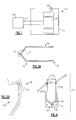
- an example electric machine 10 such as an electric generator or auxiliary power unit, is shown schematically.
- the electric machine 10 includes a stator 12 in register with a rotor 13.
- the electric machine 10 is driven by a prime mover 15, such as a gas turbine engine for aerospace application.
- a shaft 17 couples the prime mover 15 and the rotor 13.
- a housing assembly 11 includes an input housing 23 enclosing various components of the electric machine 10.
- the housing assembly to include more components and different arrangements.
- the input housing 23 encloses the stator 12 and rotor 13.
- the shaft 17 extends into the input housing 23 to couple to the rotor 13.
- the input housing 23 encloses the stator 12 and rotor 13.
- more components such as thermal devices (not shown), to be enclosed in the input housing 23 and for the housing 23 to partially cover the electric machine 10.
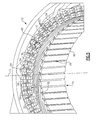
- an example stator 12 is disposed about an axis 14 and includes a plurality of slots 16 and a plurality of windings 18.
- Each of the plurality of windings 18 has a generally rectangular cross section, shown in greater detail in Figure 9A .
- the plurality of windings 18 has a generally rectangular cross section having rounded corners. At least a portion of each of the plurality of windings 18 extend into each of the plurality of slots 16.
- the plurality of slots 16 is located circumferentially around an inner circumference 20 of the stator 12.
- the plurality of slots 16 extend the length 22 of the stator 12, and is parallel to the axis 14. However, it is within the contemplation of this disclosure to use slots 16 of other lengths and orientations.
- the stator 12 includes a number of jump connections 24 that are electrically connected with current transformers 26 and phase outlets 27 to provide an electrical connection between the stator 12 and another component or device 28.
- three pairs of jump connectors 24 are shown with each jump connector 24 of a pair 180 degrees apart.
- the pairs of jump connectors 24 may also be offset by 120 degrees thereby providing a three phase alternating current arrangement.
- an example winding 18 includes a knuckle 30, a first portion 32, and a second portion 34.
- the knuckle 30 is formed by performing a twist and bend of a portion 31 of the winding 18 to create an end to insert into a slot 16 of the stator.
- a separate first portion 32 and second portion 34 of the winding 18 are created.
- the winding 18 is made of electrically conductive material, such as copper or other similarly conductive material.
- a plurality of windings 18 is at least partially inserted into each of the plurality of slots 16.
- Each of the plurality of windings 18 is inserted such that the knuckle 30 is inserted first and moves to the bottom end 40 of each slot 16.
- Both the first portion 32 and the second portion 34 of each winding 18 are located in the same slot 16.
- the first portion 32 of each winding 18 is positioned at a position radially inward of the second portion 34 relative to the axis 14. Both the first portion 32 and second portion 34 extend out from the bottom end 40 of each slot 16.
- two windings 18 are inserted into each slot 16. However, it is within the contemplation of this disclosure for each slot 16 to hold more than two windings 18.
- each first portion 32 of each winding 18 within the same slot 16 is grouped to form an inner group 46, and each second portion 34 of each winding 18 within the same slot is grouped to form an outer group 48.
- At least a part of the first portion 32 and a part of the second portion 34 extend out beyond the plurality of slots 16.
- Each of the plurality of windings 18 are enclosed in nonconductive insulation 50.
- the insulation 50 is stripped at the exposed ends 52 of the windings 18, allowing the windings 18 to electrically contact. Therefore, the exposed ends 52 are configured to allow electrical current to flow through connected windings 18.
- Jump connectors 24 are provided at certain points around the stator 12 to provide a way for the electrical current to exit the stator 12.
- the jump connectors 24 are electrically conductive and are electrically connected to the windings 18 by replacing part of the second portion 34 of one of the windings 18.
- the jump connecter 24 is brazed to second portions 34.
- the brazing consists of creating a metallurgical bond between a filler metal and the surfaces of two metals being joined, as known. However, it is within the contemplation of this disclosure to use other methods of joining windings 18 and jump connectors 24.
- the jump connector 24 By electrically connecting the jump connector 24 to the second portions 34, the jump connector 24 is able to receive current from a plurality of windings 18 and move the current from the stator 12 as described above.
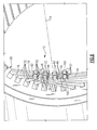
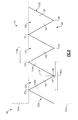
- the portion of the windings 18 located above the plurality of slots 16 are shown. As each winding 18 extends out of the slot 16, the winding 18 is bent so that the windings 18 are generally aligned with the inner circumference 20 of the stator 12, allowing non-adjacent first portions 32 and second portions 34 to align generally parallel to each other for electrical connection.
- the first portion 32 of each of the plurality of windings 18 are located radially inward of the second portions 34 of each of the plurality of windings 18. The alignment of non-adjacent first portions 32 and second portions 34 allows for continual current flow through the windings 18 without short circuiting the windings 18.
- An inner group 46 and an outer group 48 are formed from the plurality of windings 18 common to the same slot 16.
- the inner group 46 is a pair of first portions 32 and the outer group 48 is a pair of second portions 34.
- other numbers of first portions 32 and second portions to comprise the inner groups 46 and outer groups 48.
- the exposed ends 52 of the inner groups 46 and outer groups 48 are aligned such that each inner group 46 is electrically coupled to an outer group 48 from a non-adjacent slot 16.
- the aligned inner groups 46 and outer groups 48 are brazed together at the exposed ends 52 to form a braze joint 160.
- a braze clip 62 is used to aide in electrically connecting the inner groups 46 and outer groups 48.
- the braze clip 62 is made of a conductive material and allows current to flow between the inner group 46 and outer group 48.
- the braze clip 62 may be an H-clip, as shown. However, it is within the contemplation of this disclosure to use other configurations of clips as needed based on the alignment of the inner groups 46 and outer groups 48.
- the braze clip 62 is a braze alloy, such as AWS A5.8 BCup-5. The use of the braze clip 62 results in the inner group 46 being electrically and physically clamped to the outer group 48 to allow current flow between windings 18.
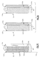
- the plurality of windings 18 maintain a generally rectangular cross section defined by pairs of opposing sides 76, 78. Each side 76, 78 of a pair may be parallel to each other and perpendicular to each side, 78, 76 respectively, of the other opposing pair. As shown, the plurality of windings 18 maintain a generally rectangular cross section while having rounded corners connecting the opposing pairs of sides 76, 78. It is within the contemplation of this disclosure for the plurality of windings to maintain a generally rectangular cross section in other arrangements which do not change the alignment of the opposing pairs of side 76, 78.
- Each pair of sides 76, 78 includes an exposed end 52 of an example winding 18 that is part of the first portion 32 and has a pairs of surfaces, 122a-b and 124a-b respectively, free of the insulation 50.
- the surface 122a-b, 124a-b of the exposed end 52 has a depth 126 measured from the top of the exposed end 52 to the beginning of the insulation 50. In one example, the depth 126 is within the range of .650-.850 inches (16.51-21.59 mm). However, it is within the contemplation of this disclosure to use other depths 126.
- a tool such as a knurling tool 127, is applied to at least one surface 122a-b, 124a-b of the exposed end 52 to knurl the surface 122, 124 to form a plurality of grooves 128 and a plurality of ridges 140 (Shown in Figure 7B ).
- the example knurling tool 127 is shown only applying to one surface 122a; however, it is within the contemplation of this disclosure for the knurling tool 127 to be applied to any or all of the surfaces 122a-b, 124a-b.
- the knurling tool 127 is configured to knurl the surface 122a when applied such that a pattern of grooves 128, or cuts, and a plurality of ridges 140 (illustrated in Figure 7B , 7C, and 7D ), are formed on the surface 122a.
- the knurling tool 127 presses into the surface 122a, displacing the core material.
- braze alloy When braze alloy is applied, it flows into the plurality of grooves 128 of the knurled surface 122a to braze the inner group 46 of the plurality of windings 18 and the outer group 48 of the plurality of windings.
- the knurling tool 127 is removed after forming a knurled surface 122a, leaving a plurality of grooves 128 and a plurality of ridges 140 on the surface 122a beyond the insulation 50.
- only surface 122a is knurled; however, it is within the contemplation of this disclosure for any of the surfaces 122a-b, 124a-b to be knurled.
- the grooves 128 and ridges 140 are formed by the knurling tool 127; however, it is within the contemplation of the invention form the grooves 128 by other means including at least stamping and molding.
- the plurality of grooves 128 and the plurality of ridges 140 are disposed on the surface 122a in a straight knurl pattern.
- Each of the plurality of grooves 128 and plurality of ridges 140 is disposed at a 45° angle 130 relative to an axis 132.
- the plurality of grooves 128 and plurality of ridges 140 to be disposed at different angles 130.
- the plurality of grooves 128 are equally spaced apart a distance 134 across the surface 122a.
- the grooves 128 are spaced at 22-28 grooves 128 per inch and the ridges 140 are spaced at 22-28 ridges 140 per inch.
- the plurality of grooves 128 is disposed along the entire depth 126 of the exposed end 52.
- a person of ordinary skill in the art can determine ideal pattern or non-pattern alignments of the plurality of grooves 128 using teachings herein.
- the plurality of grooves 128 and the plurality of ridges 140 are disposed on the surface 122a of the exposed end 52 in a diamond knurl pattern beyond the insulation 50.
- surface 122a is knurled; however, it is within the contemplation of this disclosure for any of the surfaces 122a-b, 124a-b to be knurled.
- the plurality of grooves 128 and the plurality of ridges 140 are disposed on each surface 122a-b, 124a-b of the exposed end in a straight knurl pattern beyond the insulation 50.
- the plurality of grooves 128 displaces part of the surface 122a of the first exposed end 52a, forming ridges 140.
- Each groove 128 has a cup 142, or area where the core is displaced due to knurling, below the plane of the surface 122a. Ridges 140 are formed above the plane of the surface 122a due to the displaced material of the cup 142.
- a gap 154 of the groove 128 measures from the peak 150 of each of the corresponding ridges 140a-b to the base point 148 of each groove 128.
- the base point 148 is located halfway between peaks 150 of the corresponding ridges 140a-b. In one example, when the surface 122a of the second exposed end 52b is aligned to contact the first exposed end 52a, each of the peaks 150 contact the surface 122a of the second exposed end 52b, leaving the gap 154 between the base point 148 of each groove 128 and the surface 122a of the second exposed end 52b.
- dimensions of Figure 8 are enlarged and are not drawn to scale either literally, nor with relation to each other.
- each groove 128 has a width 146a, equal to the distance 146b between each ridge 140, and in the range of .035-.045 inches (.889-.1143 mm).
- the first portion 46 includes at least two ridges 140a-b each also having a width 144 in the range of .035-.045 inches (.889-1.143 mm).
- the base point 148 is located at a position 147 that is exactly halfway between corresponding peaks 150 of the plurality of ridges 140, the position 147 in the range of .0175-.0225 inches (.4445-.5715 mm) away from each corresponding peak 150.
- positions 147 it is within the contemplation of the disclosure to use positions 147 at different distances between peaks 150.
- the gap 154 is in the range of .0003-.007 inches (.0762-.1778mm) creating a gap 154 between the surface 122a of a first exposed end 52a and the surface 122a of a second exposed end 52b of an inner group 46.
- an inner group 46 is shown, it is within the contemplation of the disclosure for this arrangement to be applicable to an outer group 48 as well as for the pair of surfaces 124a-b of each exposed end to be knurled and aligned, as will be shown in greater detail in Figures 9A and 9B .
- a braze joint 160 is formed between the inner group 46 of a slot 16.
- Another braze joint 160 is formed between the outer group 48 of another slot.
- the pair of first sides 76 are longitudinal sides, or a long side of the rectangular cross sections of each winding 18 and are aligned generally parallel to the inner circumference 20 of the stator 12.
- the windings 18 are further aligned such that at least one of the first sides 76 of each of the plurality of windings 18a-b are facing and in contact with at least one other first side 76 of another winding 18.
- the alignment causes at least one of the surface 122a-b of a first winding 18a to be facing and in contact with one of the surface 122a-b of a second winding 18b for each of the inner group 46 and the outer group 48.
- the surface 122a of at least one of the plurality of windings 18 is knurled to create a gap 154 between contacting windings 18a-b of the inner group 46 and the outer group 48.
- the gap 154 is enlarged for illustrative purposes.
- each the windings 18 are shown facing and contacting, it is within the contemplation of this invention that a surface 122a of a first winding 18a may face and contact another surface 122b of a second winding 18b.
- each of the inner group 46 and the outer group 48 has windings 18a-b with one surface 122a knurled, it is within the contemplation of this disclosure for a winding 18 to have more than one surface 122a-b, 124a-b knurled to allow use of a plurality of windings 18.
- one of the first winding 18a and the second winding 18b of each of the inner group 46 and the outer group 48 has a knurled surface 122a.
- the knurled surface 122a creates a gap 154 in the range of .0003-.007 inches (.0762-.1778mm) between the exposed end 52 of the first winding 18a and the exposed end 52a of the second winding 18b.
- the gap 154 allows braze alloy to flow between the windings 18a-b, and when brazed, form a braze joint 160 between the exposed ends 52 of the windings 18a-b with increased strength as well as proper wetting and fill as the specification of the gap 154 is determined based upon the surface tension of the braze alloy.
- both the first winding 18a and second winding 18b of each of the inner group 46 and the outer group 48 have a knurled surface 122a.
- the first winding 18a and second winding 18b are brazed together with a gap 154 in the range of .009-.014 inches (.2286-.3556 mm).
- the gap 154 allows braze alloy to flow between the windings 18a-b, and when brazed forming a braze joint 160 between the exposed ends 52 of the windings 18a-b with increased strength as well as proper wetting and fill as the specification of the gap 154 is determined based upon the surface tension of the braze alloy.
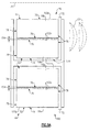
- the inner group 46 of windings 18 and outer group 48 of windings 18 are disposed in a braze clip 62.
- the braze clip 62 allows current to flow between the inner group 46 and outer group 48.
- the braze clip 62 may be an H-clip, as shown. However, it is within the contemplation of this disclosure to use other configurations of clips 62 as needed based on the alignment of the inner groups 46 and outer groups 48.
- the use of the braze clip 62 results in the inner group 46 being electrically and physically clamped to the non-adjacent outer group 48 to allow current flow between the plurality of windings 18.
- a cavity 170 is provided between the braze clip 62 and the plurality of windings 18.
- the cavity 170 is spaced a distance 172 apart from the plurality of windings 18 at all regions around the plurality of windings 18.
- the distance 172 is within the range of .006-.010 inches (.1524-.254 mm). However, it is within the contemplation of this disclosure for other distances 172 or a distance of 0 mm to be used.
- the tips 174 of the exposed ends 52 are cut off.
- the braze clip 62 is positioned at the end of the exposed ends 52 and the removal of the tips 174 reduces weight of the stator 12.
- a braze joint 160 is formed between the inner group 46 of a slot 16.
- Another braze joint 160 is formed between the outer group 48 of another slot.
- the pair of second sides 78 are non-longitudinal sides, or a short side of the rectangular cross sections of each winding 18 and are aligned generally parallel to the inner circumference 20 of the stator 12.
- the windings 18 are further aligned such that at least one of the second sides 78 of each of the plurality of windings 18a-b are facing and in contact with another second side 78 of another winding 18.
- the alignment causes at least one of the surface 124a-b of a first winding 18a to be facing and in contact with one of the surface 124a-b of a second winding 18b for each of the inner group 46 and the outer group 48.
- the surface 124a of at least one of the plurality of windings 18 is knurled to create a gap 154 between contacting windings 18a-b of the inner group 46 and the outer group 48.
- the gap 154 is enlarged for illustrative purposes.
- each the windings 18 are shown facing and contacting, it is within the contemplation of this invention that a surface 124a of a first winding 18a may face and contact another surface 124b of a second winding 18b.
- each of the inner group 46 and the outer group 48 has windings 18a-b with one surface 124a knurled, it is within the contemplation of this disclosure for a winding 18 to have more than one knurled surface to allow use of a plurality of windings 18.
- one of a first winding 18a and second winding 18b of each of the inner group 46 and the outer group 48 have a knurled surface 124a.
- the knurled surface creates a gap 154 in the range of .0003-.007 inches (.0762-.1778mm) between the exposed end 52 of the first winding 18a and the exposed end 52a of the second winding 18b.
- the gap 154 allows braze alloy to flow between the windings 18a-b, and when brazed, form a braze joint 160 between the exposed ends 52 of the windings 18a-b with increased strength as well as proper wetting and fill as the specification of the gap 154 is determined based upon the surface tension of the braze alloy.
- both the first winding 18a and the second winding 18b of each of the inner group 46 and the outer group 48 have a knurled surface 124a.
- the knurled surfaces 124a create a gap 154 in the range of .009-.014 inches (.2286-.3556 mm) between the exposed end 52 of the first winding 18a and the exposed end 52a of the second winding 18b.
- the gap 154 allows braze alloy to flow between the windings 18a-b, and when brazed, form a braze joint 160 between the exposed ends 52 of the windings 18a-b with increased strength as well as proper wetting and fill as the specification of the gap 154 is determined based upon the surface tension of the braze alloy.
- the exposed ends 52 are knurled by a knurling tool 127 to create a gap 154 between the plurality of windings 18.
- the specifications of the grooves 128 formed by knurling a surface 122a-b, 124a-b are determined at least partially by how much clearance between the plurality of windings 18 is needed. Clearance between the plurality of windings 18 depends upon the surface tension of the braze alloy, which efficiently bridge different gaps 154 depending on the braze alloy being used.
- the braze alloy is able to flow into the gaps 154 during brazing to provide effective brazing of the plurality of windings 18.
- the strength of the braze joints 160 is increased while providing proper wetting and fill of the braze joint 160.
- the braze joints 160 of the plurality of windings 18 and the braze clip 62 allow electrical current to flow through the plurality of windings 18 of the stator 12.
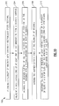
- a method for installing knurled windings within a stator 200 includes providing plurality of windings with generally rectangular cross sections 202. A first exposed end of at least one of the windings is knurled forming a grooved surface 204. The grooved surface of the first exposed end of at least one of the plurality of windings is aligned with a second exposed end of another winding 206. The aligned exposed ends of the plurality of windings are brazed together 208. The plurality of windings is at least partially inserted into each of a plurality of slots of a stator such that the windings are stacked down the longitudinal side of the slot 210.
Landscapes
- Engineering & Computer Science (AREA)
- Power Engineering (AREA)
- Manufacturing & Machinery (AREA)
- Insulation, Fastening Of Motor, Generator Windings (AREA)
- Windings For Motors And Generators (AREA)
Applications Claiming Priority (1)
| Application Number | Priority Date | Filing Date | Title |
|---|---|---|---|
| US12/870,263 US8581466B2 (en) | 2010-08-27 | 2010-08-27 | Knurled multiple conductor windings |
Publications (3)
| Publication Number | Publication Date |
|---|---|
| EP2424085A2 true EP2424085A2 (de) | 2012-02-29 |
| EP2424085A3 EP2424085A3 (de) | 2016-07-20 |
| EP2424085B1 EP2424085B1 (de) | 2019-12-04 |
Family
ID=44509015
Family Applications (1)
| Application Number | Title | Priority Date | Filing Date |
|---|---|---|---|
| EP11179114.1A Active EP2424085B1 (de) | 2010-08-27 | 2011-08-26 | Geriffelte Wicklung mit mehreren Leitern |
Country Status (5)
| Country | Link |
|---|---|
| US (1) | US8581466B2 (de) |
| EP (1) | EP2424085B1 (de) |
| CN (1) | CN102386704B (de) |
| CA (1) | CA2748605C (de) |
| ES (1) | ES2761279T3 (de) |
Families Citing this family (4)
| Publication number | Priority date | Publication date | Assignee | Title |
|---|---|---|---|---|
| EP2800248B1 (de) * | 2013-04-30 | 2021-03-24 | General Electric Technology GmbH | Statorwicklung eines elektrischen Generators |
| KR102696292B1 (ko) * | 2020-01-08 | 2024-08-20 | 엘지마그나 이파워트레인 주식회사 | 회전 전기 기기의 스테이터 |
| KR20240093940A (ko) * | 2021-10-26 | 2024-06-24 | 어탑 에스.피.에이. | 유도 권선 등의 전기 케이블들의 단부에 대한 커플링 방법 |
| US12601273B2 (en) | 2024-08-30 | 2026-04-14 | Pratt & Whitney Canada Corp. | Stator vane braze joints |
Family Cites Families (29)
| Publication number | Priority date | Publication date | Assignee | Title |
|---|---|---|---|---|
| US3165617A (en) * | 1962-07-23 | 1965-01-12 | M G Steele Co | Apparatus for joining metal wires by brazing |
| US3192423A (en) * | 1962-11-29 | 1965-06-29 | Gen Electric | Coil end connecting means for split windings of dynamoelectric machines |
| US3735088A (en) | 1971-03-08 | 1973-05-22 | Gen Electric | Brazing method and apparatus |
| US3688236A (en) | 1971-03-12 | 1972-08-29 | Westinghouse Electric Corp | Electrical inductive apparatus having serially interconnected windings |
| US4528467A (en) | 1983-09-19 | 1985-07-09 | International Business Machines Corporation | Coil for disk file actuator |
| DE3914862C2 (de) * | 1989-05-05 | 1993-12-16 | Productech Gmbh | Verfahren zur Verminderung von mechanischen Spannungen beim Schweissen |
| US5348210A (en) | 1990-06-14 | 1994-09-20 | Ball Burnishing Machine Tools Limited | Joints |
| US5507528A (en) * | 1994-09-30 | 1996-04-16 | Itt Corporation | Method of braze joint fastening for male to female receptacles |
| US6483220B1 (en) | 1995-06-22 | 2002-11-19 | Hamilton Sundstrand Corporation | Precision-wound rotor for a dynamoelectric machine |
| ES2203986T5 (es) * | 1997-10-16 | 2007-12-01 | Denso Corporation | Metodo y aparato para arrollar las partes de vuelta de segmentos conductores de estator en u. |
| US6091168A (en) | 1998-12-22 | 2000-07-18 | Hamilton Sundstrand Corporation | Rotor for a dynamoelectric machine |
| JP3201397B2 (ja) * | 1999-03-30 | 2001-08-20 | 株式会社デンソー | 回転電機の製造方法 |
| JP3589134B2 (ja) * | 2000-01-12 | 2004-11-17 | 株式会社デンソー | ステータ製造方法及びその装置 |
| JP2001286082A (ja) * | 2000-04-03 | 2001-10-12 | Mitsubishi Electric Corp | 交流発電機の固定子 |
| JP3633494B2 (ja) * | 2001-02-20 | 2005-03-30 | 株式会社デンソー | 回転電機 |
| JP4942259B2 (ja) | 2001-07-11 | 2012-05-30 | パナソニック株式会社 | 電動機 |
| JP3709823B2 (ja) * | 2001-10-05 | 2005-10-26 | 株式会社デンソー | 車両用交流発電機 |
| GB0130602D0 (en) | 2001-12-21 | 2002-02-06 | Johnson Electric Sa | Brushless D.C. motor |
| JP4019951B2 (ja) * | 2002-03-01 | 2007-12-12 | 株式会社デンソー | 回転電機の巻線の製造方法および巻線凹部の加工方法 |
| US7262537B2 (en) | 2002-07-19 | 2007-08-28 | Hamilton Sundstrand Corporation | Electric motor and generator component having a plurality of windings made from a plurality of individually conductive wires |
| FR2868620B1 (fr) * | 2004-03-31 | 2006-07-21 | Valeo Equip Electr Moteur | Induit polyphase pour machine electrique tournante, notamment un alternateur pour vehicule automobile, et son procede de fabrication |
| JP4444729B2 (ja) * | 2004-05-12 | 2010-03-31 | 株式会社日立製作所 | 電気機器巻線の接合部の評価方法および装置 |
| JP4186872B2 (ja) * | 2004-05-24 | 2008-11-26 | 株式会社デンソー | 4層型セグメント順次接合ステータコイル及びその製造方法 |
| TWI382634B (zh) | 2004-12-15 | 2013-01-11 | 松下電器產業股份有限公司 | 具雙重絕緣構造之馬達及搭載有該馬達之電子機器 |
| US7439715B2 (en) | 2006-05-22 | 2008-10-21 | Hamilton Sundstrand Corporation | Dual source power generating system |
| US8479377B2 (en) * | 2008-10-24 | 2013-07-09 | GM Global Technology Operations LLC | Methods and apparatus for a motor stator |
| JP5066062B2 (ja) * | 2008-11-21 | 2012-11-07 | 株式会社日立製作所 | 回転電機および回転電機の製造方法 |
| US8129876B2 (en) * | 2010-02-08 | 2012-03-06 | Michael Bresney | Brazed joint between a cooling fluid box and an armature bar |
| US8436506B2 (en) * | 2010-04-13 | 2013-05-07 | GM Global Technology Operations LLC | Electric motor assemblies and systems and methods associated with joining wires of electric motor assemblies |
-
2010
- 2010-08-27 US US12/870,263 patent/US8581466B2/en active Active
-
2011
- 2011-08-01 CA CA2748605A patent/CA2748605C/en active Active
- 2011-08-26 EP EP11179114.1A patent/EP2424085B1/de active Active
- 2011-08-26 ES ES11179114T patent/ES2761279T3/es active Active
- 2011-08-26 CN CN201110248161.9A patent/CN102386704B/zh active Active
Non-Patent Citations (1)
| Title |
|---|
| None |
Also Published As
| Publication number | Publication date |
|---|---|
| CN102386704B (zh) | 2014-12-17 |
| ES2761279T3 (es) | 2020-05-19 |
| EP2424085B1 (de) | 2019-12-04 |
| CN102386704A (zh) | 2012-03-21 |
| CA2748605C (en) | 2016-04-12 |
| EP2424085A3 (de) | 2016-07-20 |
| US8581466B2 (en) | 2013-11-12 |
| US20120049671A1 (en) | 2012-03-01 |
| CA2748605A1 (en) | 2012-02-27 |
Similar Documents
| Publication | Publication Date | Title |
|---|---|---|
| US9461527B2 (en) | Multiple conductor winding in stator | |
| US11984783B2 (en) | Stator, electric machine, and manufacturing process | |
| US20170237310A1 (en) | Rotary electric machine stator | |
| CN108512335A (zh) | 电马达以及用于该电马达的开关单元 | |
| CN102362416B (zh) | 成对导体端部的电连接及用于形成此连接的方法 | |
| CN103490545A (zh) | 集配电环、电动机以及电动机的制造方法 | |
| CN106208430B (zh) | 用于三相电动机的定子组件以及相关缠绕方法 | |
| CN110875666B (zh) | 具有由极链形成的定子且具有包漆铝线的无接触布线的电机 | |
| CN106537732A (zh) | 设有优化线圈的旋转电机的定子 | |
| CA2748605C (en) | Knurled multiple conductor windings | |
| US5789840A (en) | Endhead joint for stator bars | |
| CN112202262B (zh) | 配电部件 | |
| CN111344935A (zh) | 电枢的制造方法 | |
| CN113491055A (zh) | 定子以及用于生产定子的方法 | |
| KR100516853B1 (ko) | 집속단자와도출코일의결합구조및그것을이용한소형회전전기와차량용교류발전기 | |
| US10181658B2 (en) | Electric machine with electrical connector | |
| EP2930829A1 (de) | C-förmige oder U-förmige Halbspule, Rotorwicklung mit einer derartigen Halbspule und dazugehöriges Herstellungsverfahren | |
| JP2000069705A (ja) | 回転電機のステータ | |
| CN108370189A (zh) | 定子、旋转电机以及定子的制造方法 | |
| JP3977138B2 (ja) | 回転電機 | |
| EP3952068B1 (de) | Rotierende elektrische maschine | |
| CN102629726A (zh) | 线材与绞线的连接方法以及使用它的旋转电机 | |
| EP4274065A2 (de) | Elektrischer verbinder und motor damit | |
| JP2021111998A (ja) | ステータ | |
| JP2006157993A (ja) | セグメント式ステータ及びその製造方法 |
Legal Events
| Date | Code | Title | Description |
|---|---|---|---|
| AK | Designated contracting states |
Kind code of ref document: A2 Designated state(s): AL AT BE BG CH CY CZ DE DK EE ES FI FR GB GR HR HU IE IS IT LI LT LU LV MC MK MT NL NO PL PT RO RS SE SI SK SM TR |
|
| AX | Request for extension of the european patent |
Extension state: BA ME |
|
| PUAI | Public reference made under article 153(3) epc to a published international application that has entered the european phase |
Free format text: ORIGINAL CODE: 0009012 |
|
| PUAL | Search report despatched |
Free format text: ORIGINAL CODE: 0009013 |
|
| AK | Designated contracting states |
Kind code of ref document: A3 Designated state(s): AL AT BE BG CH CY CZ DE DK EE ES FI FR GB GR HR HU IE IS IT LI LT LU LV MC MK MT NL NO PL PT RO RS SE SI SK SM TR |
|
| AX | Request for extension of the european patent |
Extension state: BA ME |
|
| RIC1 | Information provided on ipc code assigned before grant |
Ipc: H02K 15/00 20060101AFI20160616BHEP Ipc: H02K 3/12 20060101ALI20160616BHEP |
|
| STAA | Information on the status of an ep patent application or granted ep patent |
Free format text: STATUS: REQUEST FOR EXAMINATION WAS MADE |
|
| 17P | Request for examination filed |
Effective date: 20170120 |
|
| RBV | Designated contracting states (corrected) |
Designated state(s): AL AT BE BG CH CY CZ DE DK EE ES FI FR GB GR HR HU IE IS IT LI LT LU LV MC MK MT NL NO PL PT RO RS SE SI SK SM TR |
|
| STAA | Information on the status of an ep patent application or granted ep patent |
Free format text: STATUS: EXAMINATION IS IN PROGRESS |
|
| 17Q | First examination report despatched |
Effective date: 20170809 |
|
| GRAP | Despatch of communication of intention to grant a patent |
Free format text: ORIGINAL CODE: EPIDOSNIGR1 |
|
| STAA | Information on the status of an ep patent application or granted ep patent |
Free format text: STATUS: GRANT OF PATENT IS INTENDED |
|
| INTG | Intention to grant announced |
Effective date: 20181221 |
|
| GRAJ | Information related to disapproval of communication of intention to grant by the applicant or resumption of examination proceedings by the epo deleted |
Free format text: ORIGINAL CODE: EPIDOSDIGR1 |
|
| STAA | Information on the status of an ep patent application or granted ep patent |
Free format text: STATUS: EXAMINATION IS IN PROGRESS |
|
| INTC | Intention to grant announced (deleted) | ||
| GRAP | Despatch of communication of intention to grant a patent |
Free format text: ORIGINAL CODE: EPIDOSNIGR1 |
|
| STAA | Information on the status of an ep patent application or granted ep patent |
Free format text: STATUS: GRANT OF PATENT IS INTENDED |
|
| INTG | Intention to grant announced |
Effective date: 20190624 |
|
| GRAS | Grant fee paid |
Free format text: ORIGINAL CODE: EPIDOSNIGR3 |
|
| GRAA | (expected) grant |
Free format text: ORIGINAL CODE: 0009210 |
|
| STAA | Information on the status of an ep patent application or granted ep patent |
Free format text: STATUS: THE PATENT HAS BEEN GRANTED |
|
| AK | Designated contracting states |
Kind code of ref document: B1 Designated state(s): AL AT BE BG CH CY CZ DE DK EE ES FI FR GB GR HR HU IE IS IT LI LT LU LV MC MK MT NL NO PL PT RO RS SE SI SK SM TR |
|
| REG | Reference to a national code |
Ref country code: GB Ref legal event code: FG4D |
|
| REG | Reference to a national code |
Ref country code: CH Ref legal event code: EP |
|
| REG | Reference to a national code |
Ref country code: AT Ref legal event code: REF Ref document number: 1210659 Country of ref document: AT Kind code of ref document: T Effective date: 20191215 |
|
| REG | Reference to a national code |
Ref country code: DE Ref legal event code: R096 Ref document number: 602011063759 Country of ref document: DE |
|
| REG | Reference to a national code |
Ref country code: IE Ref legal event code: FG4D |
|
| REG | Reference to a national code |
Ref country code: NL Ref legal event code: MP Effective date: 20191204 |
|
| REG | Reference to a national code |
Ref country code: LT Ref legal event code: MG4D |
|
| PG25 | Lapsed in a contracting state [announced via postgrant information from national office to epo] |
Ref country code: LT Free format text: LAPSE BECAUSE OF FAILURE TO SUBMIT A TRANSLATION OF THE DESCRIPTION OR TO PAY THE FEE WITHIN THE PRESCRIBED TIME-LIMIT Effective date: 20191204 Ref country code: GR Free format text: LAPSE BECAUSE OF FAILURE TO SUBMIT A TRANSLATION OF THE DESCRIPTION OR TO PAY THE FEE WITHIN THE PRESCRIBED TIME-LIMIT Effective date: 20200305 Ref country code: NO Free format text: LAPSE BECAUSE OF FAILURE TO SUBMIT A TRANSLATION OF THE DESCRIPTION OR TO PAY THE FEE WITHIN THE PRESCRIBED TIME-LIMIT Effective date: 20200304 Ref country code: BG Free format text: LAPSE BECAUSE OF FAILURE TO SUBMIT A TRANSLATION OF THE DESCRIPTION OR TO PAY THE FEE WITHIN THE PRESCRIBED TIME-LIMIT Effective date: 20200304 Ref country code: FI Free format text: LAPSE BECAUSE OF FAILURE TO SUBMIT A TRANSLATION OF THE DESCRIPTION OR TO PAY THE FEE WITHIN THE PRESCRIBED TIME-LIMIT Effective date: 20191204 Ref country code: SE Free format text: LAPSE BECAUSE OF FAILURE TO SUBMIT A TRANSLATION OF THE DESCRIPTION OR TO PAY THE FEE WITHIN THE PRESCRIBED TIME-LIMIT Effective date: 20191204 Ref country code: LV Free format text: LAPSE BECAUSE OF FAILURE TO SUBMIT A TRANSLATION OF THE DESCRIPTION OR TO PAY THE FEE WITHIN THE PRESCRIBED TIME-LIMIT Effective date: 20191204 |
|
| REG | Reference to a national code |
Ref country code: ES Ref legal event code: FG2A Ref document number: 2761279 Country of ref document: ES Kind code of ref document: T3 Effective date: 20200519 |
|
| PG25 | Lapsed in a contracting state [announced via postgrant information from national office to epo] |
Ref country code: HR Free format text: LAPSE BECAUSE OF FAILURE TO SUBMIT A TRANSLATION OF THE DESCRIPTION OR TO PAY THE FEE WITHIN THE PRESCRIBED TIME-LIMIT Effective date: 20191204 Ref country code: RS Free format text: LAPSE BECAUSE OF FAILURE TO SUBMIT A TRANSLATION OF THE DESCRIPTION OR TO PAY THE FEE WITHIN THE PRESCRIBED TIME-LIMIT Effective date: 20191204 |
|
| PG25 | Lapsed in a contracting state [announced via postgrant information from national office to epo] |
Ref country code: AL Free format text: LAPSE BECAUSE OF FAILURE TO SUBMIT A TRANSLATION OF THE DESCRIPTION OR TO PAY THE FEE WITHIN THE PRESCRIBED TIME-LIMIT Effective date: 20191204 |
|
| PG25 | Lapsed in a contracting state [announced via postgrant information from national office to epo] |
Ref country code: PT Free format text: LAPSE BECAUSE OF FAILURE TO SUBMIT A TRANSLATION OF THE DESCRIPTION OR TO PAY THE FEE WITHIN THE PRESCRIBED TIME-LIMIT Effective date: 20200429 Ref country code: CZ Free format text: LAPSE BECAUSE OF FAILURE TO SUBMIT A TRANSLATION OF THE DESCRIPTION OR TO PAY THE FEE WITHIN THE PRESCRIBED TIME-LIMIT Effective date: 20191204 Ref country code: NL Free format text: LAPSE BECAUSE OF FAILURE TO SUBMIT A TRANSLATION OF THE DESCRIPTION OR TO PAY THE FEE WITHIN THE PRESCRIBED TIME-LIMIT Effective date: 20191204 Ref country code: RO Free format text: LAPSE BECAUSE OF FAILURE TO SUBMIT A TRANSLATION OF THE DESCRIPTION OR TO PAY THE FEE WITHIN THE PRESCRIBED TIME-LIMIT Effective date: 20191204 Ref country code: EE Free format text: LAPSE BECAUSE OF FAILURE TO SUBMIT A TRANSLATION OF THE DESCRIPTION OR TO PAY THE FEE WITHIN THE PRESCRIBED TIME-LIMIT Effective date: 20191204 |
|
| PG25 | Lapsed in a contracting state [announced via postgrant information from national office to epo] |
Ref country code: SK Free format text: LAPSE BECAUSE OF FAILURE TO SUBMIT A TRANSLATION OF THE DESCRIPTION OR TO PAY THE FEE WITHIN THE PRESCRIBED TIME-LIMIT Effective date: 20191204 Ref country code: IS Free format text: LAPSE BECAUSE OF FAILURE TO SUBMIT A TRANSLATION OF THE DESCRIPTION OR TO PAY THE FEE WITHIN THE PRESCRIBED TIME-LIMIT Effective date: 20200404 Ref country code: SM Free format text: LAPSE BECAUSE OF FAILURE TO SUBMIT A TRANSLATION OF THE DESCRIPTION OR TO PAY THE FEE WITHIN THE PRESCRIBED TIME-LIMIT Effective date: 20191204 |
|
| REG | Reference to a national code |
Ref country code: DE Ref legal event code: R097 Ref document number: 602011063759 Country of ref document: DE |
|
| REG | Reference to a national code |
Ref country code: AT Ref legal event code: MK05 Ref document number: 1210659 Country of ref document: AT Kind code of ref document: T Effective date: 20191204 |
|
| PLBE | No opposition filed within time limit |
Free format text: ORIGINAL CODE: 0009261 |
|
| STAA | Information on the status of an ep patent application or granted ep patent |
Free format text: STATUS: NO OPPOSITION FILED WITHIN TIME LIMIT |
|
| PG25 | Lapsed in a contracting state [announced via postgrant information from national office to epo] |
Ref country code: DK Free format text: LAPSE BECAUSE OF FAILURE TO SUBMIT A TRANSLATION OF THE DESCRIPTION OR TO PAY THE FEE WITHIN THE PRESCRIBED TIME-LIMIT Effective date: 20191204 |
|
| 26N | No opposition filed |
Effective date: 20200907 |
|
| PG25 | Lapsed in a contracting state [announced via postgrant information from national office to epo] |
Ref country code: AT Free format text: LAPSE BECAUSE OF FAILURE TO SUBMIT A TRANSLATION OF THE DESCRIPTION OR TO PAY THE FEE WITHIN THE PRESCRIBED TIME-LIMIT Effective date: 20191204 Ref country code: PL Free format text: LAPSE BECAUSE OF FAILURE TO SUBMIT A TRANSLATION OF THE DESCRIPTION OR TO PAY THE FEE WITHIN THE PRESCRIBED TIME-LIMIT Effective date: 20191204 Ref country code: SI Free format text: LAPSE BECAUSE OF FAILURE TO SUBMIT A TRANSLATION OF THE DESCRIPTION OR TO PAY THE FEE WITHIN THE PRESCRIBED TIME-LIMIT Effective date: 20191204 |
|
| PG25 | Lapsed in a contracting state [announced via postgrant information from national office to epo] |
Ref country code: IT Free format text: LAPSE BECAUSE OF FAILURE TO SUBMIT A TRANSLATION OF THE DESCRIPTION OR TO PAY THE FEE WITHIN THE PRESCRIBED TIME-LIMIT Effective date: 20191204 |
|
| REG | Reference to a national code |
Ref country code: DE Ref legal event code: R119 Ref document number: 602011063759 Country of ref document: DE |
|
| PG25 | Lapsed in a contracting state [announced via postgrant information from national office to epo] |
Ref country code: MC Free format text: LAPSE BECAUSE OF FAILURE TO SUBMIT A TRANSLATION OF THE DESCRIPTION OR TO PAY THE FEE WITHIN THE PRESCRIBED TIME-LIMIT Effective date: 20191204 |
|
| REG | Reference to a national code |
Ref country code: CH Ref legal event code: PL |
|
| PG25 | Lapsed in a contracting state [announced via postgrant information from national office to epo] |
Ref country code: LU Free format text: LAPSE BECAUSE OF NON-PAYMENT OF DUE FEES Effective date: 20200826 Ref country code: LI Free format text: LAPSE BECAUSE OF NON-PAYMENT OF DUE FEES Effective date: 20200831 Ref country code: CH Free format text: LAPSE BECAUSE OF NON-PAYMENT OF DUE FEES Effective date: 20200831 |
|
| REG | Reference to a national code |
Ref country code: BE Ref legal event code: MM Effective date: 20200831 |
|
| PG25 | Lapsed in a contracting state [announced via postgrant information from national office to epo] |
Ref country code: FR Free format text: LAPSE BECAUSE OF NON-PAYMENT OF DUE FEES Effective date: 20200831 Ref country code: DE Free format text: LAPSE BECAUSE OF NON-PAYMENT OF DUE FEES Effective date: 20210302 |
|
| PG25 | Lapsed in a contracting state [announced via postgrant information from national office to epo] |
Ref country code: BE Free format text: LAPSE BECAUSE OF NON-PAYMENT OF DUE FEES Effective date: 20200831 Ref country code: IE Free format text: LAPSE BECAUSE OF NON-PAYMENT OF DUE FEES Effective date: 20200826 |
|
| PG25 | Lapsed in a contracting state [announced via postgrant information from national office to epo] |
Ref country code: TR Free format text: LAPSE BECAUSE OF FAILURE TO SUBMIT A TRANSLATION OF THE DESCRIPTION OR TO PAY THE FEE WITHIN THE PRESCRIBED TIME-LIMIT Effective date: 20191204 Ref country code: MT Free format text: LAPSE BECAUSE OF FAILURE TO SUBMIT A TRANSLATION OF THE DESCRIPTION OR TO PAY THE FEE WITHIN THE PRESCRIBED TIME-LIMIT Effective date: 20191204 Ref country code: CY Free format text: LAPSE BECAUSE OF FAILURE TO SUBMIT A TRANSLATION OF THE DESCRIPTION OR TO PAY THE FEE WITHIN THE PRESCRIBED TIME-LIMIT Effective date: 20191204 |
|
| PG25 | Lapsed in a contracting state [announced via postgrant information from national office to epo] |
Ref country code: MK Free format text: LAPSE BECAUSE OF FAILURE TO SUBMIT A TRANSLATION OF THE DESCRIPTION OR TO PAY THE FEE WITHIN THE PRESCRIBED TIME-LIMIT Effective date: 20191204 |
|
| PGFP | Annual fee paid to national office [announced via postgrant information from national office to epo] |
Ref country code: ES Payment date: 20250901 Year of fee payment: 15 |
|
| PGFP | Annual fee paid to national office [announced via postgrant information from national office to epo] |
Ref country code: GB Payment date: 20250724 Year of fee payment: 15 |
|
| P01 | Opt-out of the competence of the unified patent court (upc) registered |
Free format text: CASE NUMBER: UPC_APP_0016467_2424085/2025 Effective date: 20251209 |