EP2425896B1 - Seringue pour l'utilisation à l'aide d'un dispositif de dosage - Google Patents
Seringue pour l'utilisation à l'aide d'un dispositif de dosage Download PDFInfo
- Publication number
- EP2425896B1 EP2425896B1 EP11006564.6A EP11006564A EP2425896B1 EP 2425896 B1 EP2425896 B1 EP 2425896B1 EP 11006564 A EP11006564 A EP 11006564A EP 2425896 B1 EP2425896 B1 EP 2425896B1
- Authority
- EP
- European Patent Office
- Prior art keywords
- syringe
- plunger
- floor
- cylinder
- receiver
- Prior art date
- Legal status (The legal status is an assumption and is not a legal conclusion. Google has not performed a legal analysis and makes no representation as to the accuracy of the status listed.)
- Active
Links
Images


Classifications
-
- B—PERFORMING OPERATIONS; TRANSPORTING
- B01—PHYSICAL OR CHEMICAL PROCESSES OR APPARATUS IN GENERAL
- B01L—CHEMICAL OR PHYSICAL LABORATORY APPARATUS FOR GENERAL USE
- B01L3/00—Containers or dishes for laboratory use, e.g. laboratory glassware; Droppers
- B01L3/02—Burettes; Pipettes
- B01L3/021—Pipettes, i.e. with only one conduit for withdrawing and redistributing liquids
- B01L3/0217—Pipettes, i.e. with only one conduit for withdrawing and redistributing liquids of the plunger pump type
- B01L3/0234—Repeating pipettes, i.e. for dispensing multiple doses from a single charge
-
- A—HUMAN NECESSITIES
- A61—MEDICAL OR VETERINARY SCIENCE; HYGIENE
- A61M—DEVICES FOR INTRODUCING MEDIA INTO, OR ONTO, THE BODY; DEVICES FOR TRANSDUCING BODY MEDIA OR FOR TAKING MEDIA FROM THE BODY; DEVICES FOR PRODUCING OR ENDING SLEEP OR STUPOR
- A61M5/00—Devices for bringing media into the body in a subcutaneous, intra-vascular or intramuscular way; Accessories therefor, e.g. filling or cleaning devices, arm-rests
- A61M5/178—Syringes
- A61M5/31—Details
- A61M5/315—Pistons; Piston-rods; Guiding, blocking or restricting the movement of the rod or piston; Appliances on the rod for facilitating dosing ; Dosing mechanisms
- A61M5/31511—Piston or piston-rod constructions, e.g. connection of piston with piston-rod
- A61M5/31513—Piston constructions to improve sealing or sliding
-
- A—HUMAN NECESSITIES
- A61—MEDICAL OR VETERINARY SCIENCE; HYGIENE
- A61M—DEVICES FOR INTRODUCING MEDIA INTO, OR ONTO, THE BODY; DEVICES FOR TRANSDUCING BODY MEDIA OR FOR TAKING MEDIA FROM THE BODY; DEVICES FOR PRODUCING OR ENDING SLEEP OR STUPOR
- A61M5/00—Devices for bringing media into the body in a subcutaneous, intra-vascular or intramuscular way; Accessories therefor, e.g. filling or cleaning devices, arm-rests
- A61M5/178—Syringes
- A61M5/31—Details
- A61M5/315—Pistons; Piston-rods; Guiding, blocking or restricting the movement of the rod or piston; Appliances on the rod for facilitating dosing ; Dosing mechanisms
- A61M5/31565—Administration mechanisms, i.e. constructional features, modes of administering a dose
- A61M5/31566—Means improving security or handling thereof
- A61M5/31573—Accuracy improving means
-
- A—HUMAN NECESSITIES
- A61—MEDICAL OR VETERINARY SCIENCE; HYGIENE
- A61M—DEVICES FOR INTRODUCING MEDIA INTO, OR ONTO, THE BODY; DEVICES FOR TRANSDUCING BODY MEDIA OR FOR TAKING MEDIA FROM THE BODY; DEVICES FOR PRODUCING OR ENDING SLEEP OR STUPOR
- A61M5/00—Devices for bringing media into the body in a subcutaneous, intra-vascular or intramuscular way; Accessories therefor, e.g. filling or cleaning devices, arm-rests
- A61M5/178—Syringes
- A61M5/31—Details
- A61M2005/3117—Means preventing contamination of the medicament compartment of a syringe
- A61M2005/3118—Means preventing contamination of the medicament compartment of a syringe via the distal end of a syringe, i.e. syringe end for mounting a needle cannula
-
- A—HUMAN NECESSITIES
- A61—MEDICAL OR VETERINARY SCIENCE; HYGIENE
- A61M—DEVICES FOR INTRODUCING MEDIA INTO, OR ONTO, THE BODY; DEVICES FOR TRANSDUCING BODY MEDIA OR FOR TAKING MEDIA FROM THE BODY; DEVICES FOR PRODUCING OR ENDING SLEEP OR STUPOR
- A61M5/00—Devices for bringing media into the body in a subcutaneous, intra-vascular or intramuscular way; Accessories therefor, e.g. filling or cleaning devices, arm-rests
- A61M5/178—Syringes
- A61M5/31—Details
- A61M5/315—Pistons; Piston-rods; Guiding, blocking or restricting the movement of the rod or piston; Appliances on the rod for facilitating dosing ; Dosing mechanisms
- A61M5/31511—Piston or piston-rod constructions, e.g. connection of piston with piston-rod
- A61M2005/31516—Piston or piston-rod constructions, e.g. connection of piston with piston-rod reducing dead-space in the syringe barrel after delivery
-
- B—PERFORMING OPERATIONS; TRANSPORTING
- B01—PHYSICAL OR CHEMICAL PROCESSES OR APPARATUS IN GENERAL
- B01L—CHEMICAL OR PHYSICAL LABORATORY APPARATUS FOR GENERAL USE
- B01L2200/00—Solutions for specific problems relating to chemical or physical laboratory apparatus
- B01L2200/06—Fluid handling related problems
- B01L2200/0605—Metering of fluids
-
- B—PERFORMING OPERATIONS; TRANSPORTING
- B01—PHYSICAL OR CHEMICAL PROCESSES OR APPARATUS IN GENERAL
- B01L—CHEMICAL OR PHYSICAL LABORATORY APPARATUS FOR GENERAL USE
- B01L2300/00—Additional constructional details
- B01L2300/08—Geometry, shape and general structure
- B01L2300/0848—Specific forms of parts of containers
- B01L2300/0851—Bottom walls
Definitions
- the invention relates to a syringe with syringe barrel and syringe plunger for use with a metering device having a receptacle for the syringe barrel and an axially displaceable piston receptacle for the syringe plunger.
- Pipettes are dosing devices for measuring and transferring liquids. They are often designed as repeating or multipette, which are used together with a syringe to receive liquid into the syringe and gradually release from it.
- a repeating pipette is from the DE 29 26 691 C2 and the US 4,406,170 known.
- the syringe holder is a U-shaped groove in a pipette housing into which a syringe flange can be inserted through a lateral housing opening. In the recording, the syringe flange is loaded by a compression spring in the direction of the discharge opening.
- the syringe piston has a cylindrical actuating portion, which can be fixed by means of a clamping device in a receiving body.
- a piston push-back device is designed as a lever of the receiving body, which protrudes through a side housing slot. By moving the lever away from the syringe flange, the plunger can be withdrawn from the syringe.
- the Kolbenvorschiebe is a rack-pawl device, wherein the rack connected to the receiving body and the pawl is pivotally mounted on a reciprocating drive lever. When the drive lever is pivoted toward the syringe flange, the pawl engages and carries the rack and associated piston in the same direction. When swiveling in the opposite direction, the pawl springs out of the sawtooth-shaped toothing and the piston position does not change.
- a Whitweiteneinstell Steiner has a coupled with a knob tongue, which covers the toothing more or less depending on the position of the knob.
- the portion of the latch movement is adjustable, in which this engages in the rack and entrains the piston.
- the volume of liquid delivered by the syringe at each dosing step is adjustable by means of the rotary knob.
- the syringe sits in her shots with a certain play.
- the sliding devices are subject to a game.
- the piston is moved after pulling out at constant pitch setting in a first advancing step by a different distance than in the subsequent steps.
- the amount of liquid expelled during the first step thus deviates considerably from the liquid output of each subsequent step. For accurate dosing, therefore, one discards in practice the volume of liquid expelled during the first step. As a result, sample liquid is lost.
- the EP 0 679 439 B1 and US 5 591 408 describe a further developed repeating pipette, which has a constant stepping device for reducing the loss of sample liquid, which sets the width of the first dispensing step to a constant value irrespective of the setting of the setting element for the further subsequent steps.
- the DE 43 41 229 C2 and the US 5,620,660 propose a more suitable for the manual operation pipette system with a simple axially inserted into the pipette or removable from this syringe.
- This pipette system has a syringe having a mounting portion and a syringe plunger and a pipette having in a pipette housing a receptacle for the mounting portion and a receiving body with a plunger receptacle for the syringe plunger and a piston rod connected thereto.
- Fastening devices for reversibly or releasably fixing of mounting portion and syringe piston in the recordings and piston adjusting devices for moving the receiving body in the pipette housing available.
- the attachment portion and the syringe plunger are axially slidable into their attachment positions by axial openings of their receptacles.
- the fastening devices have radially deliverable gripping devices for fixing the fastening section and the syringe piston in the fastening positions.
- the gripping means have pivotally mounted in the pipette syringe gripping lever and pivotally mounted in the receiving body piston gripping lever.
- the syringe gripping levers and the plunger gripping levers are two-armed with a gripping arm and an actuating arm, wherein the syringe gripper levers on the inner sides of their actuating arms have contact points which are by pressing their actuating arms outwardly pivotable against the actuating arms of the piston gripping lever and actuate the piston gripping levers.
- the attachment portion is a syringe flange and according to another embodiment, the syringe piston has a piston collar for engaging behind by the gripping devices.
- the commercial embodiments Multipette ® (plus / stream / Xstream) of this dosing Eppendorf AG include syringes Combitips ® (plus) having a cylinder with a piston movement area on the inside, and a syringe flange at the upper end of the cylinder.
- the syringes are offered with different filling volumes (0.1 ml, 0.2 ml, 0.5 ml, 1 ml, 2.5 ml, 5 ml and 10 ml).
- the system includes syringes Combitips® (plus) with volumes of 25 ml and 50 ml.
- syringes have a large cross-section, and are connected via an adapter with a Repetierpipette.
- the adapter is connected at a large diameter via a bayonet connection with the upper edge of the syringe barrel. Above it wears a smaller diameter sleeve with a flange corresponding to the syringe flange of the smaller syringes.
- the adapter is connected to the repeating pipette via the syringe flange.
- the known dosing system allows accurate dosages with low errors.
- the object of the invention is to make available a syringe for use with a metering device which allows even more precise metering.
- the invention is based on the surprising finding of the Applicant that in the stepwise dispensing of sample liquid in the last dosing step a slightly larger amount of liquid is dispensed than in the preceding dispensing steps. Furthermore, extensive investigations by the Applicant have led to the surprising result that this increased fluid delivery is based on the fact that during the last dosing step the bottom of the syringe cylinder deforms inwardly into the syringe cylinder by a very small amount. The Applicant has found that this is due to the radial expansion of the syringe barrel by the approach to the bottom of the sealing lip of the syringe plunger.
- the syringe of the invention overcomes this effect in that it comprises stop means which limit the displacement of the syringe plunger towards the bottom so that the syringe plunger with the plunger seal can only be approached to the ground up to a certain distance.
- This distance is chosen so as to reduce or avoid the deformation of the soil which leads to increased discharge of liquid as the piston seal approaches. It is preferably 1 mm and more.
- the lower piston section largely fills the volume in the syringe barrel below the piston seal.
- the lower piston portion is dimensioned so that air pockets occur as little as possible, the flow resistance in the resulting gap in the residual amount but remains within the acceptable range in which the force to be applied is subjectively not too large at residual amount.
- the width of a gap between the lower piston portion and the lower end portion of the syringe barrel is a few tenths of a millimeter.
- the slings between syringe barrel and syringe plunger can be designed differently.
- the stop means on a circumferential inner stage of the syringe barrel which is arranged at a distance from the bottom and limits the displacement of the syringe plunger to the bottom.
- the displacement of the syringe piston is limited by the fact that the sealing lip rests against the inner stage of the syringe barrel.
- a syringe barrel having an inner stage has below the inner stage a lower end region with a preferably reduced inner diameter. This is based on the production of the syringe barrel by injection molding.
- the syringe plunger engages in this lower end region with a lower piston portion of reduced diameter, when the syringe plunger is inserted as far as possible into the syringe barrel.
- the syringe cylinder has at least adjacent to the bottom outside axially over its circumference extended ribs.
- the axial ribs counteract a radial expansion of the syringe barrel during insertion of the syringe plunger and a deformation of the bottom into the syringe barrel.
- the syringe barrel has externally axially extended ribs in the reduced diameter lower end region.
- the axial ribs are preferably dimensioned such that they lie within the imaginary extension of the shell of the syringe barrel in the piston barrel region. The ribs then do not protrude beyond the jacket of the syringe barrel in the piston barrel area.
- the axial ribs are distributed uniformly over the circumference of the syringe barrel.
- syringes ritips® professional e.g. 10 ml
- which has eight radially extended ribs on the bottom have eight radially extended ribs on the bottom.
- these radially extending ribs have a maximum height of less than one millimeter at the exit of the soil and their height decreases radially outwardly to zero at the outer periphery of the soil.
- These ribs are apparently appropriate for aesthetic reasons. Due to their design and course, the radially extending ribs are unsuitable for reducing inversion of the bottom into the syringe barrel in the final dispensing step.
- the ribs at least at the outer end of a height of at least 3 mm, further preferably at least 5 mm.
- an inversion of the bottom is further reduced in the syringe barrel during the last dosing.
- the invention includes embodiments in which the radial ribs have a constant height or the height of the radial ribs increases to exit from the bottom. According to one embodiment, the height of the radial ribs decreases towards the outlet. This can avoid that the ribs interfere with the recording and dispensing of sample liquid. According to a further embodiment, the radial ribs are distributed uniformly in the circumferential direction over the ground.
- the syringe barrel has a cylindrical extension extending laterally across the bottom and the radial ribs extend radially inwards from the inside of this extension. This will further stiffen the soil.
- the outlet is arranged in a metering tip projecting outside from the bottom.
- the radial ribs preferably run flat towards the metering tip.
- the syringe plunger has at the bottom a Verdrängerspitze which engages in the dosing tip when the syringe plunger is inserted as far as possible in the syringe barrel.
- a small gap between the displacement tip and dosing tip is then preferably present. As a result, an air cushion between the syringe plunger and the liquid absorbed is counteracted.
- the bottom has a downwardly tapering, conical shape. This shape, in combination with radial ribs whose height decreases toward the exit, prevents the radial ribs from interfering with the picking and dispensing of liquid.
- the syringe piston on a piston head, which is connected via a push rod with the coupling piece.
- the push rod on several extended longitudinally wing pieces. The wing pieces favor a stable push rod with low material usage.
- the means for holding a one-piece connected to the syringe barrel flange and / or connected to the syringe barrel adapter with a flange and / or means for connecting the syringe barrel with an adapter is preferably connected by bayonet connection or screw with the syringe barrel.
- the piston seal is a sealing lip on the circumference of the syringe plunger.
- the sealing lip is an aligned at an acute angle to the circumference of the syringe plunger sleeve.
- the sealing lip is directed towards the ground.
- the syringe according to the invention is preferably produced with filling volumes of 10 ml, 12.5 ml, 25 ml and 50 ml. In conventional syringes with the mentioned filling volumes, the metering error during the last metering step is especially significant.
- the syringe cylinder and / or the syringe plunger are each made in one piece from plastic.
- top and bottom refer to the preferred orientation of the syringe during dosing, in which the syringe is held vertically with the exit at the bottom and the coupler at the top.
- corresponding parts of various embodiments are provided with a plurality of reference numerals separated by a dot, with the digits before the dot coinciding and the digits standing behind the dot denoting the respective embodiment.
- corresponding parts of various embodiments are also referred to alone with the matching numbers.
- a conventional syringe 1.1 has a syringe barrel 2.1 that has a conical downwardly tapered bottom 3.1 at the bottom. At the lowest point of the bottom 3.1 is a downwardly projecting, down conically tapered dosing 4.1.
- the dosing tip 4.1 has an outlet 5.1 for liquid.
- the syringe barrel 2.1 has at the upper edge 6.1 an outwardly projecting flange 7.1. Furthermore, from the upper edge 6.1 three projections 8.1 still further than the flange 7.1 outwards. The projections 8.1 are distributed uniformly over the circumference of the syringe barrel. The projections 8.1 form a bayonet connection with an adapter, not shown, for holding the syringe barrel 2.1 in a dosing device, not shown.
- the upper edge 6.1 surrounds an opening 9.1, which serves for inserting a syringe plunger. Adjacent to the opening 9.1, the syringe barrel has inside a short insertion bevel 10.1. This is followed by a running area 11.1 for a syringe plunger, which extends to the bottom 3.1.
- a syringe plunger 12.1 is used in the syringe barrel 2.1 .
- the syringe plunger 12.1 has a substantially conical piston head 13.1 below.
- the piston head 13.1 is provided on the outer circumference with a cross-sectionally V-shaped sealing lip 14.1.
- the sealing lip 14.1 lies with its outer end circumferentially on the inside of the piston running area 11.1.
- the sealing lip 14.1 is open with its V-shaped cross section towards the bottom 3.1.
- the piston head 13.1 carries a push rod 15.1, which is formed over a majority of four strip-shaped wing pieces 16.1, which are aligned in a cross-section in a horizontal cross-section to each other.
- a push rod 15.1 which is formed over a majority of four strip-shaped wing pieces 16.1, which are aligned in a cross-section in a horizontal cross-section to each other.
- the Wing pieces 16.1 At the top sits on the Wing pieces 16.1 a circular disk 17.1.
- a coupling piece 18.1 which has a series in the axial direction one behind the other, circular disk-shaped projections 19.1.
- the coupling piece 18.1 can be inserted into a piston receptacle of a dosing device, not shown, and is held therein by means of suitable retaining means.
- the piston head 13.1 has a downwardly projecting, downwardly conically tapered Verdrängerspitze 20.1.
- the taper of the piston head 13.1 is adapted to the conicity of the bottom 3.1 and the conicity of the positive tip 20.1 to the taper of the dosing tip 4.1, without the piston head on the bottom 3.1 and the Verdrängerspitze 20.1 is seated on the dosing tip 4.1 when the syringe plunger 12.1 completely in the syringe barrel 2.1 is inserted.
- the syringe barrel 2.1 and the syringe plunger 12.1 are each injection molded in one piece from a plastic, wherein z.
- the syringe barrel 2.1 made of polypropylene and the syringe plunger 12.1 is injection molded from polyethylene.
- the Applicant has found that when inserting the syringe plunger 12.1 into the syringe barrel 2.1, the syringe barrel 2.1 radially widens over the sealing lip 14.1. When the syringe plunger is seated on the bottom 3.1 with the sealing lip 14.1 during the last metering step, this has the effect that the syringe bottom 3.1 deforms somewhat inwards into the syringe barrel 2.1.
- FIG. 3 This is through Fig. 3 illustrated.
- the deformation of the syringe barrel shown is based on FEM calculations (calculations according to the finite element method). In these calculations, only the displacement of the soil with respect to its starting position in the axial direction was considered.
- syringe barrel 2.1 is shown in dashed lines in the undeformed state when the syringe plunger 12.1 is not inserted. Furthermore, the syringe barrel 2.1 is shown in solid lines in the situation in which the syringe plunger 12.1 is fully inserted. It can be clearly seen that the syringe bottom 3.1 bulges into the interior of the syringe barrel 2.1.
- Fig. 3 the extent of deformation of the soil 3.1 is characterized by different shades of gray.
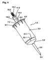
- the syringe 1.2 in accordance with the invention Fig. 4 and 5 differs from the above-described characterized in that the syringe barrel 2.2 at a distance from the bottom of the inner circumference 3.2 has a narrow shoulder 21.1.
- the shoulder 21.1 tapers conically downwards.
- Above the shoulder 21.1 is the piston running area 11.2 of the syringe 1.2.
- the syringe barrel 2.2 has a cylindrical lower end portion 22.1 of reduced diameter.
- the syringe piston 12.2 differs from the previously described 12.1 in that the conical piston head 13.2 has a smaller diameter with a cylindrical portion 23.1 projecting from the upper edge. The upper edge of the cylindrical portion 23.1 is connected to the V-shaped sealing lip 14.2, whose shape and dimensions are as in the sealing lip 14.1.
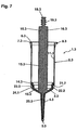
- the syringe 1.3 has the special feature that the syringe cylinder 2.3 has ribs 24.1 axially extended beyond the lower end region 22.2 of reduced diameter.
- the axial ribs 24.1 extend from the outside of the inner step 21.2 almost to the floor 3.3. Their height is chosen so that they do not stand over the mantle of the syringe barrel 2.3. About 10 to 30 axial ribs 24.1 are evenly distributed over the circumference of the syringe barrel 2.3.
- the sealing lip sits 14.2 bw. 14.3 on the inner stage 21.1 or 21.2 and prevents further displacement of the syringe plunger 12.2 or 12.3 to the bottom 3.2 or 3.3.
- the piston head 13.2 or 13.3 is by a small gap from the bottom 3.2 or 3.3 and the Verdrängerspitze 20.2 or 20.3 is spaced by a small gap of the metering tip 4.2 or 4.3.
- the radial deformation caused by the sealing lip 14.2 or 14.3 thus does not affect the bottom 3.2 or 3.3.
- the syringe 1.3 also contribute to the axial ribs 24.1, which stabilize the shape of the syringe barrel 2.3.
- Fig. 8 shows the results of another FEM calculation for the axial deformation of the syringe cylinder 2.3 of the syringe 1.3 of Fig. 6 and 7 , In dashed lines again the undeformed syringe barrel 2.3 is shown. In solid lines, the syringe barrel is deformed by the syringe plunger 12.3 pushed to the stop. The scale is the same as in Fig. 3 , The deformations of the spray bottom 3.3 are extremely low. The shades of gray show that the outer areas of the floor 3.3 are deformed somewhat more strongly than the central areas.
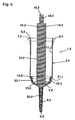
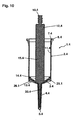
- the Fig. 9 and 10 show a further syringe according to the invention 1.4. This differs from the syringe 1.1 only in that the jacket of the syringe barrel 2.4 has an extension 25.1, which is slightly above the bottom 3.4 addition. In the area of the extension 25.1, the wall thickness of the syringe barrel 2.4 is greater than over the running area 11.4.
- the syringe barrel 2.4 has a plurality of (eg 10 to 30) radially extended ribs 26.1 on the underside of the bottom.
- the radial ribs 26.1 have adjacent to the extension 25.1 their greatest height. This is at least 3 mm. Starting from the outer circumference, the height of the ribs 26.1 decreases as far as the dosing tip 4.4.
- the radial ribs 26.1 are evenly distributed over the bottom 3.4.
- the radial ribs 26.1 cause a stabilization of the bottom 3.4, which greatly reduces deformation of the bottom 3.4 when the sealing lip 14.4 on the inside of the bottom 3.4. touches down. To reduce the deformation of the bottom 3.4 also contributes to the extension 25.1.
- Fig. 11 and 12 show a further syringe according to the invention 1.5, wherein the syringe barrel 2.5 has an inner stage 21.3 and the syringe plunger 12.5 as the syringe plunger 12.2 is formed.
- the syringe cylinder 2.5 has outer (approximately 10 to 30) axial ribs 24.2 and the bottom 3.5 has outer radial ribs 26.2.
- the axial ribs 24.2 extend to the bottom 3.5 and go there in the radial ribs 26.2 over. At the outer circumference of the bottom 3.5, the radial ribs are significantly higher than in the syringe 1.4.
Landscapes
- Health & Medical Sciences (AREA)
- Heart & Thoracic Surgery (AREA)
- Animal Behavior & Ethology (AREA)
- Veterinary Medicine (AREA)
- Vascular Medicine (AREA)
- Engineering & Computer Science (AREA)
- Anesthesiology (AREA)
- Public Health (AREA)
- Hematology (AREA)
- Biomedical Technology (AREA)
- Life Sciences & Earth Sciences (AREA)
- General Health & Medical Sciences (AREA)
- Clinical Laboratory Science (AREA)
- Chemical & Material Sciences (AREA)
- Chemical Kinetics & Catalysis (AREA)
- Infusion, Injection, And Reservoir Apparatuses (AREA)
Claims (17)
- Seringue pour l'utilisation à l'aide d'un dispositif de dosage avec un logement pour un cylindre de seringue et un logement de piston déplaçable axialement pour un piston de seringue, avec- un cylindre de seringue (2),- qui a en bas un fond (3) avec une sortie (5),- intérieurement une zone de mouvement de piston (11) cylindrique, et- en haut des moyens pour la retenue (8) dans le logement,- avec un piston de seringue, (12)- qui a à la périphérie un joint d'étanchéité de piston (14) périphérique pour réaliser une étanchéité sur la zone de mouvement de piston (11) et- en haut une pièce d'accouplement (18) pour l'introduction dans le logement de piston, et- avec des moyens de butée (21) entre le cylindre de seringue (2) et le piston de seringue (12), qui limitent le déplacement du piston de seringue (12) vers le fond (3) de telle sorte que le piston de seringue, (12) avec le joint d'étanchéité de piston (14) ne peut être rapproché du fond (3) que jusqu'à une distance définie.
- Seringue selon la revendication 1, dans laquelle le piston présente, au-dessous du joint d'étanchéité de piston (14), un tronçon de piston inférieur (23) qui engrène dans une zone d'extrémité inférieure du cylindre de seringue, (2) quand le joint d'étanchéité de piston (14) est rapproché du fond (3) jusqu'à une distance définie.
- Seringue selon la revendication 1 ou 2, dans laquelle les moyens de butée (21) présentent un gradin intérieur (21) périphérique du cylindre de seringue (2) qui est disposé à une distance du fond (3) et qui limite le déplacement du piston de seringue, (12) vers le fond (3), et dans laquelle le cylindre de seringue (2) présente, au-dessous du gradin intérieur (21), une zone d'extrémité inférieure (22) avec un diamètre intérieur réduit.
- Seringue selon la revendication 3, dans laquelle le piston de seringue (12) présente, au-dessous du joint d'étanchéité de piston (14), un tronçon de piston inférieur (13, 23) d'un diamètre réduit qui engrène dans la zone d'extrémité inférieure (22) du cylindre de seringue (2) quand le joint d'étanchéité de piston (14) est rapproché du fond (3) jusqu'à une distance définie.
- Seringue selon une des revendications 1 à 4, dans laquelle le cylindre de seringue, (12) présente, au moins de façon adjacente au fond (3), des nervures (24) s'étendant à l'extérieur axialement sur sa périphérie.
- Seringue selon les revendications 3 et 5, dans laquelle le cylindre de seringue, (2) présente, dans la zone d'extrémité inférieure (22) de diamètre réduit, des nervures (24) s'étendant à l'extérieur axialement.
- Seringue pour l'utilisation à l'aide d'un dispositif de dosage avec un logement pour un cylindre de seringue et un logement de piston déplaçable axialement pour un piston de seringue, avec- un cylindre de seringue (2),- qui a en bas un fond (3) avec une sortie (5),- des nervures (26) s'étendant radialement sur le côté extérieur du fond (3), avec une hauteur de nervure d'au moins 1 mm au moins à l'extrémité extérieure,- à l'intérieur une zone de mouvement de piston (11) cylindrique, et- en haut des moyens pour la retenue (8) dans le logement, et- avec un piston de seringue (12),- qui a à la périphérie un joint d'étanchéité de piston (14) périphérique pour réaliser l'étanchéité sur la zone de mouvement de piston (11) et- en haut une pièce d'accouplement (18) pour l'introduction dans le logement de piston.
- Seringue selon une des revendications 1 à 6, avec les caractéristiques de la revendication 7.
- Seringue selon la revendication 7 ou 8, dans laquelle les nervures (26) radiales présentent, au moins à l'extrémité extérieure, une hauteur d'au moins 3 millimètres.
- Seringue selon une des revendications 7 à 9, dans laquelle la hauteur des nervures (26) radiales diminue vers la sortie (5).
- Seringue selon une des revendications 1 à 9, dans laquelle le fond (3) a une forme cylindrique ou une forme conique se rétrécissant vers le bas.
- Seringue selon une des revendications 1 à 10, dans laquelle la sortie (5) est disposée dans une pointe de dosage (4) dépassant extérieurement du fond (3).
- Seringue selon la revendication 11, dans laquelle le piston de seringue (12) présente en bas une pointe de déplacement (20) qui engrène dans la pointe de dosage (4) quand le piston de seringue (12) est poussé le plus loin possible dans le cylindre de seringue (2).
- Seringue selon une des revendications 1 à 13, dans laquelle le piston de seringue, (12) présente une tête de piston (13) qui est raccordée à la pièce d'accouplement (18) par le biais d'une tige de poussoir (15).
- Seringue selon la revendication 14, dans laquelle la tige de poussoir (15) comprend plusieurs pièces d'ailette (16) s'étendant dans la direction longitudinale.
- Seringue selon une des revendications 1 à 15, dans laquelle les moyens pour la retenue (8) sont une bride raccordée d'une seule pièce avec le cylindre de seringue, (2) et/ou un adaptateur raccordé au cylindre de seringue, (2) avec une bride et/ou des moyens pour le raccordement du cylindre de seringue (2) à un adaptateur.
- Seringue selon une des revendications 1 à 16, dans laquelle le cylindre de seringue (2) et/ou le piston de seringue (12) sont respectivement fabriqués d'une pièce en matière plastique.
Applications Claiming Priority (1)
| Application Number | Priority Date | Filing Date | Title |
|---|---|---|---|
| DE102010035891A DE102010035891A1 (de) | 2010-08-30 | 2010-08-30 | Spritze für den Gebrauch mit einer Dosiervorrichtung |
Publications (2)
| Publication Number | Publication Date |
|---|---|
| EP2425896A1 EP2425896A1 (fr) | 2012-03-07 |
| EP2425896B1 true EP2425896B1 (fr) | 2015-07-29 |
Family
ID=44677305
Family Applications (1)
| Application Number | Title | Priority Date | Filing Date |
|---|---|---|---|
| EP11006564.6A Active EP2425896B1 (fr) | 2010-08-30 | 2011-08-10 | Seringue pour l'utilisation à l'aide d'un dispositif de dosage |
Country Status (5)
| Country | Link |
|---|---|
| US (1) | US8839685B2 (fr) |
| EP (1) | EP2425896B1 (fr) |
| JP (1) | JP5825933B2 (fr) |
| CN (1) | CN102430438B (fr) |
| DE (1) | DE102010035891A1 (fr) |
Families Citing this family (19)
| Publication number | Priority date | Publication date | Assignee | Title |
|---|---|---|---|---|
| PL3260822T3 (pl) * | 2016-06-21 | 2021-02-08 | Eppendorf Ag | Wielokanałowa strzykawka do stosowania z urządzeniem dozującym |
| CN106047660A (zh) * | 2016-07-07 | 2016-10-26 | 李丽倩 | 一种核酸提取仪用核酸提取装置 |
| US10821053B2 (en) | 2016-10-07 | 2020-11-03 | Becton, Dickinson And Company | Syringe with connector |
| USD825750S1 (en) | 2017-02-23 | 2018-08-14 | Brand Gmbh + Co Kg | Dispenser tip |
| USD877896S1 (en) * | 2017-10-25 | 2020-03-10 | Ritter Gmbh | Syringe for medical use |
| CN111655375B (zh) * | 2017-11-30 | 2022-08-23 | 康宁股份有限公司 | 双轴取向的热塑性移液器、其形成方法和设备 |
| US11369954B2 (en) | 2019-10-25 | 2022-06-28 | Mettler-Toledo Rainin, LLC | Powered positive displacement pipette assembly |
| US11471878B2 (en) | 2019-10-25 | 2022-10-18 | Mettler-Toledo Rainin, LLC | Powered positive displacement pipette |
| US11446672B2 (en) | 2019-10-25 | 2022-09-20 | Mettler-Toledo Rainin, LLC | Powered positive displacement pipette syringe piston grasping mechanism |
| US11911767B2 (en) | 2019-10-25 | 2024-02-27 | Mettler-Toledo Rainin, LLC | Positive displacement pipette syringe identification system |
| US11389792B2 (en) * | 2019-10-25 | 2022-07-19 | Mettler-Toledo Rainin, LLC | Syringe for powered positive displacement pipette |
| CN111530518B (zh) * | 2020-06-19 | 2022-09-23 | 华兰生物云阳县单采血浆有限公司 | 一种医学检验用定量移液装置 |
| KR20240164970A (ko) * | 2020-08-11 | 2024-11-21 | 바이엘 헬쓰케어 엘엘씨 | 혈관 조영술 주사기의 피처 |
| USD982157S1 (en) * | 2021-03-12 | 2023-03-28 | Mettler-Toledo Rainin, LLC | Pipette syringe |
| USD982176S1 (en) * | 2021-03-12 | 2023-03-28 | Mettler-Toledo Rainin, LLC | Pipette syringe |
| USD976438S1 (en) * | 2021-03-12 | 2023-01-24 | Mettler-Toledo Rainin, LLC | Pipette syringe |
| US12472491B2 (en) | 2022-06-28 | 2025-11-18 | Mettler-Toledo Rainin, LLC | Positive displacement pipette syringe with reduced fluid drag |
| DE102022128810B3 (de) | 2022-10-31 | 2024-02-01 | Eppendorf Se | Kolbenstange, Kolben-Zylinder-System sowie Flüssigkeitsdosiervorrichtung mit einem solchen Kolben-Zylinder-System |
| CN117232896B (zh) * | 2023-08-09 | 2024-08-06 | 华南农业大学 | 一种调节式的河口底泥采集装置及其控制方法 |
Family Cites Families (24)
| Publication number | Priority date | Publication date | Assignee | Title |
|---|---|---|---|---|
| NL265346A (fr) * | 1960-06-10 | |||
| DE2926691C2 (de) | 1979-07-02 | 1983-05-26 | Eppendorf Gerätebau Netheler + Hinz GmbH, 2000 Hamburg | Repetierpipette |
| JPS5825171A (ja) * | 1981-08-06 | 1983-02-15 | テルモ株式会社 | シリンジ |
| US4483825A (en) * | 1982-07-09 | 1984-11-20 | Fatches Keith R | Pipette and filter combination |
| ATE127026T1 (de) * | 1989-11-08 | 1995-09-15 | Napoleon Curie | Spritze mit zurückziehbarer nadelhalterung. |
| US5300031A (en) * | 1991-06-07 | 1994-04-05 | Liebel-Flarsheim Company | Apparatus for injecting fluid into animals and disposable front loadable syringe therefor |
| ES2158886T3 (es) * | 1992-12-01 | 2001-09-16 | Tetsuro Higashikawa | Jeringuilla. |
| DE4341229C2 (de) | 1993-12-03 | 1995-09-07 | Eppendorf Geraetebau Netheler | Pipettensystem |
| DE4414760C1 (de) | 1994-04-27 | 1995-08-24 | Eppendorf Geraetebau Netheler | Repetierpipette |
| EP0951306B1 (fr) * | 1996-11-12 | 2005-07-20 | Medrad Inc. | Seringues preremplissables et injecteurs convenant a de telles seringues |
| US6626862B1 (en) * | 2000-04-04 | 2003-09-30 | Acist Medical Systems, Inc. | Fluid management and component detection system |
| US7198619B2 (en) * | 2002-03-26 | 2007-04-03 | Ultradent Products, Inc. | Valve syringe |
| WO2003093108A1 (fr) * | 2002-04-05 | 2003-11-13 | Comar, Inc. | Dispositif d'administration de medicaments et procede et systeme permettant de le fabriquer |
| DE10237770B4 (de) * | 2002-08-17 | 2006-11-09 | Eppendorf Ag | Pipettiervorrichtung |
| DE20303231U1 (de) * | 2003-02-27 | 2003-04-30 | Braun Melsungen Ag | Spritzenzylinder mit Kanülenaufsatz |
| US20050063857A1 (en) * | 2003-09-23 | 2005-03-24 | Alheidt Thomas A. | Flush syringe having anti-reflux stopper |
| DE102005023203B4 (de) | 2005-05-20 | 2009-06-04 | Eppendorf Ag | Pipette |
| FR2895920B1 (fr) * | 2006-01-06 | 2008-04-18 | Gilson Sas Soc Par Actions Sim | Pipette multivolumes. |
| WO2007094833A1 (fr) * | 2006-02-14 | 2007-08-23 | Battelle Memorial Institute | Systeme de comptage precis |
| US8137303B2 (en) * | 2006-05-08 | 2012-03-20 | Becton, Dickinson And Company | Vascular access device cleaning status indication |
| EP2032467B1 (fr) * | 2006-06-13 | 2010-08-18 | Nordson Corporation | Seringue de distribution de liquide |
| US20090004063A1 (en) * | 2007-06-29 | 2009-01-01 | Symyx Technologies, Inc. | Apparatus and method for actuating a syringe |
| DE102009016590A1 (de) * | 2009-03-31 | 2010-10-07 | Eppendorf Ag | Dosiervorrichtung |
| DE102009034897A1 (de) * | 2009-07-27 | 2011-02-03 | Eppendorf Ag | Spritze, Spritzenfamilie und Dosiervorrichtung |
-
2010
- 2010-08-30 DE DE102010035891A patent/DE102010035891A1/de not_active Withdrawn
-
2011
- 2011-08-10 EP EP11006564.6A patent/EP2425896B1/fr active Active
- 2011-08-17 US US13/211,886 patent/US8839685B2/en active Active
- 2011-08-29 JP JP2011186359A patent/JP5825933B2/ja active Active
- 2011-08-30 CN CN201110251645.9A patent/CN102430438B/zh active Active
Also Published As
| Publication number | Publication date |
|---|---|
| JP2012045396A (ja) | 2012-03-08 |
| CN102430438B (zh) | 2015-07-15 |
| EP2425896A1 (fr) | 2012-03-07 |
| DE102010035891A1 (de) | 2012-03-01 |
| US20120204660A1 (en) | 2012-08-16 |
| JP5825933B2 (ja) | 2015-12-02 |
| CN102430438A (zh) | 2012-05-02 |
| US8839685B2 (en) | 2014-09-23 |
Similar Documents
| Publication | Publication Date | Title |
|---|---|---|
| EP2425896B1 (fr) | Seringue pour l'utilisation à l'aide d'un dispositif de dosage | |
| EP2606977B1 (fr) | Embout de pipette | |
| EP1559480B1 (fr) | Pipette avec mécanisme de déplacement fixé de façon détachable au mécanisme d'actionnement | |
| DE69022714T2 (de) | Statische Mischvorrichtung. | |
| EP2539060B1 (fr) | Système mélangeur et distributeur comprenant un dispositif de mélange de type seringue à élément de mélange actionnable distalement | |
| EP3680016B1 (fr) | Pipette destinée à une utilisation avec une pointe de pipette | |
| DE2343687B2 (de) | Dosiergeraet zur abgabe von fluessigkeit aus einem behaelter | |
| EP0923993A1 (fr) | Distributeur de fluide | |
| DE102006029753A1 (de) | Inhalator für pulverförmige Substanzen | |
| DE10217655B4 (de) | Einwegventil zur Abgabe eines fließfähigen Materials | |
| WO2019228682A1 (fr) | Embout de pipette | |
| DE2309547C3 (de) | Gerät zum Füllen und Entleeren eines Flüssigkeitsbehälters, z.B. einer Pipette | |
| EP3680017B1 (fr) | Pipette destinée à une utilisation avec une pointe de pipette | |
| EP1212984B1 (fr) | Seringue pour l'administration dosée de produits dentaires | |
| EP3831486A1 (fr) | Famille de pointes de pipette comprenant les pointes de pipette destinées à l'utilisation avec des pipettes d'une famille de pipettes et famille de pipettes comprenant les pipettes destinées à l'utilisation avec des pointes de pipette d'une famille de pointes de pipette | |
| EP2129465B1 (fr) | Procédé et dispositif pour la distribution dosée d'un milieu | |
| DE10258140B4 (de) | System zum Befüllen von Applikationsbehältern | |
| EP2934753B1 (fr) | Pipette pour dosage | |
| DE3541378A1 (de) | Verfahren zur begrenzung der foerdermenge einer pumpe sowie kleine handbetaetigte pumpe und spritze mit tropfenzaehler, die sich dieses verfahrens bedienen | |
| WO2009059894A1 (fr) | Appareil manuel d'ihhalation de substances | |
| EP2925457A1 (fr) | Dispositif de distribution actionné par levier, pour un milieu fluide | |
| EP0388651A2 (fr) | Dispositif pour décharger un fluide | |
| DE2647883A1 (de) | Pipettiervorrichtung | |
| EP4252710A1 (fr) | Dispositif d'injection sans aiguille d'un fluide dans un animal | |
| EP2363354B1 (fr) | Distributeur d'agent actif |
Legal Events
| Date | Code | Title | Description |
|---|---|---|---|
| AK | Designated contracting states |
Kind code of ref document: A1 Designated state(s): AL AT BE BG CH CY CZ DE DK EE ES FI FR GB GR HR HU IE IS IT LI LT LU LV MC MK MT NL NO PL PT RO RS SE SI SK SM TR |
|
| AX | Request for extension of the european patent |
Extension state: BA ME |
|
| PUAI | Public reference made under article 153(3) epc to a published international application that has entered the european phase |
Free format text: ORIGINAL CODE: 0009012 |
|
| 17P | Request for examination filed |
Effective date: 20120512 |
|
| GRAP | Despatch of communication of intention to grant a patent |
Free format text: ORIGINAL CODE: EPIDOSNIGR1 |
|
| INTG | Intention to grant announced |
Effective date: 20150217 |
|
| GRAS | Grant fee paid |
Free format text: ORIGINAL CODE: EPIDOSNIGR3 |
|
| GRAA | (expected) grant |
Free format text: ORIGINAL CODE: 0009210 |
|
| AK | Designated contracting states |
Kind code of ref document: B1 Designated state(s): AL AT BE BG CH CY CZ DE DK EE ES FI FR GB GR HR HU IE IS IT LI LT LU LV MC MK MT NL NO PL PT RO RS SE SI SK SM TR |
|
| REG | Reference to a national code |
Ref country code: GB Ref legal event code: FG4D Free format text: NOT ENGLISH |
|
| REG | Reference to a national code |
Ref country code: CH Ref legal event code: EP |
|
| REG | Reference to a national code |
Ref country code: AT Ref legal event code: REF Ref document number: 738838 Country of ref document: AT Kind code of ref document: T Effective date: 20150815 |
|
| REG | Reference to a national code |
Ref country code: IE Ref legal event code: FG4D Free format text: LANGUAGE OF EP DOCUMENT: GERMAN |
|
| REG | Reference to a national code |
Ref country code: DE Ref legal event code: R096 Ref document number: 502011007413 Country of ref document: DE |
|
| REG | Reference to a national code |
Ref country code: LT Ref legal event code: MG4D |
|
| REG | Reference to a national code |
Ref country code: NL Ref legal event code: MP Effective date: 20150729 |
|
| PG25 | Lapsed in a contracting state [announced via postgrant information from national office to epo] |
Ref country code: NO Free format text: LAPSE BECAUSE OF FAILURE TO SUBMIT A TRANSLATION OF THE DESCRIPTION OR TO PAY THE FEE WITHIN THE PRESCRIBED TIME-LIMIT Effective date: 20151029 Ref country code: LT Free format text: LAPSE BECAUSE OF FAILURE TO SUBMIT A TRANSLATION OF THE DESCRIPTION OR TO PAY THE FEE WITHIN THE PRESCRIBED TIME-LIMIT Effective date: 20150729 Ref country code: GR Free format text: LAPSE BECAUSE OF FAILURE TO SUBMIT A TRANSLATION OF THE DESCRIPTION OR TO PAY THE FEE WITHIN THE PRESCRIBED TIME-LIMIT Effective date: 20151030 Ref country code: FI Free format text: LAPSE BECAUSE OF FAILURE TO SUBMIT A TRANSLATION OF THE DESCRIPTION OR TO PAY THE FEE WITHIN THE PRESCRIBED TIME-LIMIT Effective date: 20150729 Ref country code: LV Free format text: LAPSE BECAUSE OF FAILURE TO SUBMIT A TRANSLATION OF THE DESCRIPTION OR TO PAY THE FEE WITHIN THE PRESCRIBED TIME-LIMIT Effective date: 20150729 |
|
| PG25 | Lapsed in a contracting state [announced via postgrant information from national office to epo] |
Ref country code: RS Free format text: LAPSE BECAUSE OF FAILURE TO SUBMIT A TRANSLATION OF THE DESCRIPTION OR TO PAY THE FEE WITHIN THE PRESCRIBED TIME-LIMIT Effective date: 20150729 Ref country code: IS Free format text: LAPSE BECAUSE OF FAILURE TO SUBMIT A TRANSLATION OF THE DESCRIPTION OR TO PAY THE FEE WITHIN THE PRESCRIBED TIME-LIMIT Effective date: 20151129 Ref country code: HR Free format text: LAPSE BECAUSE OF FAILURE TO SUBMIT A TRANSLATION OF THE DESCRIPTION OR TO PAY THE FEE WITHIN THE PRESCRIBED TIME-LIMIT Effective date: 20150729 Ref country code: PT Free format text: LAPSE BECAUSE OF FAILURE TO SUBMIT A TRANSLATION OF THE DESCRIPTION OR TO PAY THE FEE WITHIN THE PRESCRIBED TIME-LIMIT Effective date: 20151130 Ref country code: PL Free format text: LAPSE BECAUSE OF FAILURE TO SUBMIT A TRANSLATION OF THE DESCRIPTION OR TO PAY THE FEE WITHIN THE PRESCRIBED TIME-LIMIT Effective date: 20150729 Ref country code: ES Free format text: LAPSE BECAUSE OF FAILURE TO SUBMIT A TRANSLATION OF THE DESCRIPTION OR TO PAY THE FEE WITHIN THE PRESCRIBED TIME-LIMIT Effective date: 20150729 Ref country code: SE Free format text: LAPSE BECAUSE OF FAILURE TO SUBMIT A TRANSLATION OF THE DESCRIPTION OR TO PAY THE FEE WITHIN THE PRESCRIBED TIME-LIMIT Effective date: 20150729 |
|
| PG25 | Lapsed in a contracting state [announced via postgrant information from national office to epo] |
Ref country code: NL Free format text: LAPSE BECAUSE OF FAILURE TO SUBMIT A TRANSLATION OF THE DESCRIPTION OR TO PAY THE FEE WITHIN THE PRESCRIBED TIME-LIMIT Effective date: 20150729 |
|
| REG | Reference to a national code |
Ref country code: CH Ref legal event code: PL |
|
| PG25 | Lapsed in a contracting state [announced via postgrant information from national office to epo] |
Ref country code: CH Free format text: LAPSE BECAUSE OF NON-PAYMENT OF DUE FEES Effective date: 20150831 Ref country code: CZ Free format text: LAPSE BECAUSE OF FAILURE TO SUBMIT A TRANSLATION OF THE DESCRIPTION OR TO PAY THE FEE WITHIN THE PRESCRIBED TIME-LIMIT Effective date: 20150729 Ref country code: LI Free format text: LAPSE BECAUSE OF NON-PAYMENT OF DUE FEES Effective date: 20150831 Ref country code: EE Free format text: LAPSE BECAUSE OF FAILURE TO SUBMIT A TRANSLATION OF THE DESCRIPTION OR TO PAY THE FEE WITHIN THE PRESCRIBED TIME-LIMIT Effective date: 20150729 Ref country code: MC Free format text: LAPSE BECAUSE OF FAILURE TO SUBMIT A TRANSLATION OF THE DESCRIPTION OR TO PAY THE FEE WITHIN THE PRESCRIBED TIME-LIMIT Effective date: 20150729 Ref country code: DK Free format text: LAPSE BECAUSE OF FAILURE TO SUBMIT A TRANSLATION OF THE DESCRIPTION OR TO PAY THE FEE WITHIN THE PRESCRIBED TIME-LIMIT Effective date: 20150729 Ref country code: SK Free format text: LAPSE BECAUSE OF FAILURE TO SUBMIT A TRANSLATION OF THE DESCRIPTION OR TO PAY THE FEE WITHIN THE PRESCRIBED TIME-LIMIT Effective date: 20150729 |
|
| REG | Reference to a national code |
Ref country code: DE Ref legal event code: R097 Ref document number: 502011007413 Country of ref document: DE |
|
| PG25 | Lapsed in a contracting state [announced via postgrant information from national office to epo] |
Ref country code: RO Free format text: LAPSE BECAUSE OF FAILURE TO SUBMIT A TRANSLATION OF THE DESCRIPTION OR TO PAY THE FEE WITHIN THE PRESCRIBED TIME-LIMIT Effective date: 20150729 |
|
| REG | Reference to a national code |
Ref country code: IE Ref legal event code: MM4A |
|
| PLBE | No opposition filed within time limit |
Free format text: ORIGINAL CODE: 0009261 |
|
| STAA | Information on the status of an ep patent application or granted ep patent |
Free format text: STATUS: NO OPPOSITION FILED WITHIN TIME LIMIT |
|
| 26N | No opposition filed |
Effective date: 20160502 |
|
| PG25 | Lapsed in a contracting state [announced via postgrant information from national office to epo] |
Ref country code: IE Free format text: LAPSE BECAUSE OF NON-PAYMENT OF DUE FEES Effective date: 20150810 |
|
| REG | Reference to a national code |
Ref country code: FR Ref legal event code: PLFP Year of fee payment: 6 |
|
| PG25 | Lapsed in a contracting state [announced via postgrant information from national office to epo] |
Ref country code: SI Free format text: LAPSE BECAUSE OF FAILURE TO SUBMIT A TRANSLATION OF THE DESCRIPTION OR TO PAY THE FEE WITHIN THE PRESCRIBED TIME-LIMIT Effective date: 20150729 |
|
| PG25 | Lapsed in a contracting state [announced via postgrant information from national office to epo] |
Ref country code: MT Free format text: LAPSE BECAUSE OF FAILURE TO SUBMIT A TRANSLATION OF THE DESCRIPTION OR TO PAY THE FEE WITHIN THE PRESCRIBED TIME-LIMIT Effective date: 20150729 |
|
| PG25 | Lapsed in a contracting state [announced via postgrant information from national office to epo] |
Ref country code: BG Free format text: LAPSE BECAUSE OF FAILURE TO SUBMIT A TRANSLATION OF THE DESCRIPTION OR TO PAY THE FEE WITHIN THE PRESCRIBED TIME-LIMIT Effective date: 20150729 Ref country code: SM Free format text: LAPSE BECAUSE OF FAILURE TO SUBMIT A TRANSLATION OF THE DESCRIPTION OR TO PAY THE FEE WITHIN THE PRESCRIBED TIME-LIMIT Effective date: 20150729 Ref country code: HU Free format text: LAPSE BECAUSE OF FAILURE TO SUBMIT A TRANSLATION OF THE DESCRIPTION OR TO PAY THE FEE WITHIN THE PRESCRIBED TIME-LIMIT; INVALID AB INITIO Effective date: 20110810 |
|
| PG25 | Lapsed in a contracting state [announced via postgrant information from national office to epo] |
Ref country code: CY Free format text: LAPSE BECAUSE OF FAILURE TO SUBMIT A TRANSLATION OF THE DESCRIPTION OR TO PAY THE FEE WITHIN THE PRESCRIBED TIME-LIMIT Effective date: 20150729 |
|
| PG25 | Lapsed in a contracting state [announced via postgrant information from national office to epo] |
Ref country code: BE Free format text: LAPSE BECAUSE OF NON-PAYMENT OF DUE FEES Effective date: 20150831 |
|
| REG | Reference to a national code |
Ref country code: FR Ref legal event code: PLFP Year of fee payment: 7 |
|
| PG25 | Lapsed in a contracting state [announced via postgrant information from national office to epo] |
Ref country code: TR Free format text: LAPSE BECAUSE OF FAILURE TO SUBMIT A TRANSLATION OF THE DESCRIPTION OR TO PAY THE FEE WITHIN THE PRESCRIBED TIME-LIMIT Effective date: 20150729 |
|
| REG | Reference to a national code |
Ref country code: AT Ref legal event code: MM01 Ref document number: 738838 Country of ref document: AT Kind code of ref document: T Effective date: 20160810 |
|
| PG25 | Lapsed in a contracting state [announced via postgrant information from national office to epo] |
Ref country code: AT Free format text: LAPSE BECAUSE OF NON-PAYMENT OF DUE FEES Effective date: 20160810 |
|
| PG25 | Lapsed in a contracting state [announced via postgrant information from national office to epo] |
Ref country code: LU Free format text: LAPSE BECAUSE OF NON-PAYMENT OF DUE FEES Effective date: 20150810 |
|
| PG25 | Lapsed in a contracting state [announced via postgrant information from national office to epo] |
Ref country code: MK Free format text: LAPSE BECAUSE OF FAILURE TO SUBMIT A TRANSLATION OF THE DESCRIPTION OR TO PAY THE FEE WITHIN THE PRESCRIBED TIME-LIMIT Effective date: 20150729 |
|
| REG | Reference to a national code |
Ref country code: FR Ref legal event code: PLFP Year of fee payment: 8 |
|
| PG25 | Lapsed in a contracting state [announced via postgrant information from national office to epo] |
Ref country code: AL Free format text: LAPSE BECAUSE OF FAILURE TO SUBMIT A TRANSLATION OF THE DESCRIPTION OR TO PAY THE FEE WITHIN THE PRESCRIBED TIME-LIMIT Effective date: 20150729 |
|
| REG | Reference to a national code |
Ref country code: FR Ref legal event code: PLFP Year of fee payment: 12 |
|
| REG | Reference to a national code |
Ref country code: DE Ref legal event code: R081 Ref document number: 502011007413 Country of ref document: DE Owner name: EPPENDORF SE, DE Free format text: FORMER OWNER: EPPENDORF AG, 22339 HAMBURG, DE |
|
| P01 | Opt-out of the competence of the unified patent court (upc) registered |
Effective date: 20230527 |
|
| PGFP | Annual fee paid to national office [announced via postgrant information from national office to epo] |
Ref country code: DE Payment date: 20250820 Year of fee payment: 15 |
|
| PGFP | Annual fee paid to national office [announced via postgrant information from national office to epo] |
Ref country code: IT Payment date: 20250820 Year of fee payment: 15 |
|
| PGFP | Annual fee paid to national office [announced via postgrant information from national office to epo] |
Ref country code: GB Payment date: 20250820 Year of fee payment: 15 |
|
| PGFP | Annual fee paid to national office [announced via postgrant information from national office to epo] |
Ref country code: FR Payment date: 20250829 Year of fee payment: 15 |